2ACK6STRM3Active speaker system
CABASSE SA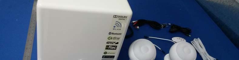
Click to zoom
Application Details
- Equipment Class
- DTS - Digital Transmission System
- Date of Grant
- Jul 20, 2014
- Application Purpose
- Original Equipment
- Date of Application
- Jul 20, 2014
- Equipment Note
- Active speaker system
- Frequency Range
- 2412.00000000 - 2462.00000000
- Company
- CABASSE SA
- Country
- France
Documents & Files
Document Text
Text extracted from the exhibit documents filed with the FCC. Open a document above to read the original.
Users Manual
notice d , installation owner , s manual betriebsanleitung STREAM 3 CAB_Stream3_FR-GB-DE.indd 104/06/13 16:15 f r a n c a i sd e u t s c he n g l i s h 23 1 2 CAB_Stream3_FR-GB-DE.indd 204/06/13 16:15 23 4 3 ETHERNET RESET WPS FULL AUTO ECO AUTO WiFi POWER ETHERNET CONFIGURATION WiFi CONFIGURATION POWER MODE MIN MAX R L SPEAKER L R OFF POWER EGATLOVTUPNI ANALOG INPUT OPTICAL INPUT RECEIVER 110-120V/220-240V WARNING: AVIS: TSA120WBi ON :EPYTESUF 110V-120VAC 220V-240VAC LEVEL WOOFER (Ant.) CAB_Stream3_FR-GB-DE.indd 304/06/13 16:15 f r a n c a i sd e u t s c he n g l i s h 45 1 2 5 7 3 4 6 8 IDENTIFYING CONTROLS IDENTIFICATION DES COMMANDES ANORDNUNG DER EDIENENELEMENTE 1On/StandbyMise en Marche / Veille Umschalten zwischen Einsschalt- und Bereitsschaftszustand 2VOL -Volume DOWNDiminution du volumeVerringern der Lautstärke 3VOL +Volume UPAugmentation du volumeErhöhen der Lautstärke 4 Mute on/offActive et désactive la coupure du sonSchaltet der Ton ein oder aus 5 Reverse scanning (wifi mode)Retour rapide (mode wifi) Suchlauf - (WLAN Modus) 6 Forward scanning (wifi mode) Avance rapide (mode wifi) Suchlauf + (WLAN Modus) 7 Pause Lecture (mode wifi) Pause Wiedergabe starten / unterbrechen (Pause)(WLAN modus) 8 Source selectionSelection de la sourceWahl der Tonquelle CAB_Stream3_FR-GB-DE.indd 404/06/13 16:15 Pause Play (wifi mode) 55 45 7 8 Connecter les satellites: le câble marqué «L» sera utilisée pour l’enceinte de gauche, le «R» pour la droite. Réunir une sphère et un socle, connecter les 2 prises, insérer l’ensemble dans la goutière, fermer avec la base. Connect the satellites: «L» plug for the left satellite and «R» for the right one. Join a sphere and a base, connect both plugs, insert them in the slot, close the base with the bottom plate. Anschluss der Satelliten: Führen Sie das Kabel an der „L“-Buchse an den linken Satelliten, das an der „R“-Buchse an den rechten. Verbinden Sie die Lautsprecherkugeln mit ihren Basen, verbinden Sie beide Stecker mit den jeweiligen Gegenstücken, schieben Sie beide Verbindungen in den dafür vorgesehenen Schlitz und verschließen Sie dann die Basen mit Hilfe der Bodenplatten. Brancher le cable haut-parleur à l’arrière du caisson de graves Stream 3. Amener le cable avec la prise droite (R) vers la position choisie pour le satellite droit, celui marqué (L) vers la position du satellite gauche. Connect the loudspeaker cable in the SPEAKER socket on the back of the Stream 3 subwoofer. Route the «R» plug to the position for the right satellite, the «L» one to the position of the left satellite. Verbinden Sie die Lautsprecherkabel mit den „SPEAKER“-Buchsen auf der Rückseite des Subwoofers. Benutzen Sie das Kabel mit der Kennzeichnung „R“ für den Satelliten auf der rechten Seite, das Kabel mit „L“ für den auf der linken Seite. INSTALLATION RAPIDE QUICK PLUG & PLAY KURZANLEITUNG INSTALLATION Déterminer la place des satellites et du caisson de graves Stream 3 : voir aussi autre suggestion page 3. Choose the positions for the satellites and the Stream 3 subwoofer. Also consider the suggestion on page 3. Wählen Sie einen Aufstellungsort für die Satelliten und den Stream 3-Subwoofer. Beachten Sie dabei auch unsere andere Empfehlungen auf Seite 3. CAB_Stream3_FR-GB-DE.indd 504/06/13 16:15 6 f r a n c a i s d e u t s c he n g l i s h 67 9 Positionner le module IR à un endroit d’où il sera discrètement visible, si possible près du capteur du téléviseur en cas d'utilisation Audio-Video du Stream 3. Le brancher sur la prise «IR REMOTE RECEIVER» Place the IR module where it will be discrete but visible. We recommend placing it near the IR receiver of the television set if the Stream 3 is also used to play AV sound. . Connect the cable into the «IR REMOTE RECEIVER» of the subwoofer CONNEXION FILAIRE AVEC UNE SOURCE AUDIO OU AUDIO-VIDEO Choisissez une source audio ( lecteur CD, dock lecteur MP3) ou audio vidéo (écran plat, décodeur, serveur) avec soit une connexion analogique RCA-RCA ou digitale optique S-PDIF. Pour la connexion analogique, faire corres- pondre la sortie droite de la source et l’entree droite du Stream 3 avec les fiches rouges du câble RCA-RCA. Les fiches RCA de l'extrémi- té du câble équipée d'une ferrite cylindrique seront branchées sur le Stream 3. POUR UNE UTILISATION SANS CONNECTION FILAIRE ANALOGIQUE OU OPTIQUE S-PDIF,ALLER DIRECTE- MENT A L'ETAPE 14. Connect the Stream 3 subwoofer to your TV set. Use the optical cable if your TV is fitted with a digital audio output and connect it to the «OPTICAL INPUT» of the Stream 3. Otherwise use the RCA-RCA cable between the «Audio Out» of the TV and the «ANALOG INPUT» of the Stream 3. The red RCA sockets must be used for the right output of the TV and the right input of the Stream 3 subwoofer so as not to invert the channels. The end of the RCA cable fitted with a cylindrical ferrite must be connected to the Stream 3 subwoofer. IF NO ANALOG OR OPTICAL WIRED CONNECTION WILL BE USED, GO DIRECT TO STEP 14. Choisir le mode veille avec le sélecteur POWER MODE : - FULL AUTO: les modules Bluetooth, wifi et DLNA restent actifs pendant la veille. Toute activation d'une source audio reconnue déclenche la sortie de veille du Stream 3. - ECO AUTO: mode veille avec consommation minimale (0,19W). Le Stream 3 ne peut être activé qu'avec la télécommande Stream ou avec la mise en route d'une source analogique ou optique. ATTENTION : La sélection du mode veille est prise en compte à la mise sous tension. Il faut donc éteindre et rallumer l'appareil avec l'interrupteur power pour valider un changement de mode. 10 11 Platzieren Sie den IR-(Fernbedinungs)-Empfänger an einem unauffälligen, aber trotzdem sichtbaren Ort. Wir empfehlen für die Benutzung gemeinsam mit einem Fernseher eine Platzierung nahe dessen IR-Empfänger. Schließen Sie das Kabel des IR-Empfängers an die Buchse „IR REMOTE RECEIVER“ des Subwoofers an. Verbinden Sie das Stream 3-System mit Ihrem Fernseher. Falls das Fernsehgerät über einen optischen Digitalausgang verfügt…
Text truncated - open the document above for the full version.
Cover Letter(s)
SCS-F18: Project and Product Certification Representative Authorization Letter Page 1 of 3 Rev 4.0 775 Montague Expressway Milpitas, CA 95035 Tel: 408-526-1188 Fax: 408-526-1088 Email: [email protected] Project and Product Certification Representative Authorization Letter Revision History Reason for Amendment (current / obsolete) From To Approved Date Initial Release (obsolete) 1.0 1.0 Nov-14-2006 Revised wording (obsolete) 1.0 2.0 Sept–25-2007 Updated company template (obsolete) 2.0 3.0 Jan-31-2012 Updated letter information (current) 3.0 4.0 May-23-2014 SCS-F18: Project and Product Certification Representative Authorization Letter Page 2 of 3 Rev 4.0 CABASSE SA 210. RUE RENE DESCARTES-BP 10,29280 PLOUZANE, FRANCE 2014-7-2 To: SIEMIC, INC. 775 Montague Expressway, Milpitas, CA 95035 USA Dear Sir/Madam, Re: Product Certification Representative Authorization Letter We, CABASSE SA hereby authorize SIEMIC, Inc. to act as a Certification Body for certifying for the following project(s): FCC ID: 2ACK6STRM3 Model: STREAM 3 Product: Active Speaker System Sincerely, signature : name / title: KERNEIS David / Electronic engineer address: 210. RUE RENE DESCARTES-BP 10,29280 PLOUZANE, FRANCE SCS-F18: Project and Product Certification Representative Authorization Letter Page 3 of 3 Rev 4.0 CABASSE SA 210. RUE RENE DESCARTES-BP 10,29280 PLOUZANE, FRANCE 2014-7-2 To: SIEMIC, Inc. 775 Montague Expressway, Milpitas, CA 95035 USA Dear Sir/Madam, Re: Project and Product Certification Representative Authorization Letter We, CABASSE SA hereby authorize SIEMIC, Inc. to act as Certification Body for certifying for the following project(s): FCC ID: 2ACK6STRM3 Model: STREAM 3 Product: Active Speaker System We affirm that between SIEMIC, Inc. and CABASSE SA, any difference in understanding, including test plan, measurement methods, applicable standards and relevant procedures and processes have been resolved prior to commencement of testing activities. Sincerely, signature : name / title: KERNEIS David / Electronic engineer address: 210. RUE RENE DESCARTES-BP 10,29280 PLOUZANE, FRANCE
Cover Letter(s)
SCS-F19: Confidentiality Request Letter Page 1 of 2 Rev 3.0 775 Montague Expressway Milpitas, CA 95035 Tel: 408-526-1188 Fax: 408-526-1088 Email: [email protected] Confidentiality Request Letter Revision History Reason for Amendment (current / obsolete) From To Approved Date Initial Release (obsolete) 1.0 1.0 Nov-14-2006 Adding CFR 2.459 (obsolete) 1.0 2.0 August – 11 - 2008 Updated company template & Added text box (current) 2.0 3.0 Jan-31-2012 SCS-F19: Confidentiality Request Letter Page 2 of 2 Rev 3.0 CABASSE SA 210. RUE RENE DESCARTES-BP 10,29280 PLOUZANE, FRANCE 2014-7-2 To: Federal Communications Commission Authorization and Evaluation Division 7435 Oakland Mills Road Columbia, MD Subject: Permanent Confidentiality Request for FCC ID: 2ACK6STRM3 We hereby request confidential treatment of information accompanying this application as outlined below: Block Diagram Schematics Operational Description The above materials contain trade secrets and proprietary information not customarily released to the public. The public disclosure of these materials may be harmful to the applicant and provide unjustified benefits to its competitors. The applicant understands that pursuant to Section 0.457 & 0.459 of the Rules, disclosure of this application and all accompanying documentation will not be made before the date of the Grant for this application. Sincerely, signature : name / title: KERNEIS David / Electronic engineer address: 210. RUE RENE DESCARTES-BP 10,29280 PLOUZANE, FRANCE
Cover Letter(s)
CABASSE SA 210. RUE RENE DESCARTES-BP 10,29280 PLOUZANE, FRANCE FCC ID: 2ACK6STRM3 To Whom It May Concern: We, the undersigned, hereby attest to the fact that we will apply the Declaration of Conformity procedure to the class B computer peripheral portion of this composite device. We understand that devices subject to the DoC procedure are required to be tested to show compliance with the FCC technical regulations by a recognized accredited testing laboratory. The testing laboratory must be accredited by a Commission approved accreditation body or designated under the terms of a government-to-government Mutual Recognition Agreement (MRA). A listing of those accredited testing laboratories that have been recognized by the Commission is published on the FCC Test facilities located in countries, where the U.S. does not have an operational Telcom MRA are not recognized by the FCC to test for the DoC procedure. Sincerely, signature : name / title: KERNEIS David / Electronic engineer address: 210. RUE RENE DESCARTES-BP 10,29280 PLOUZANE, FRANCE
ID Label/Location Info
Label location
Internal Photos
WIFI antenna BT Antenna
RF Exposure Info
FCC ID: 2ACK6STRM3 1. RF EXPOSURE EVALUATION 1.1. Limits The criteria listed in the following table shall be used to evaluate the environment impact of human exposure to radio frequency (RF) radiation as specified in 1.1307(b) Limits for Maximum Permissible Exposure (MPE) f = frequency in MHz Friis transmission formula: Pd = (Pout*G)/(4*pi*r 2 ) Where Pd = power density in mW/cm 2 , Pout = output power to antenna in mW; G = gain of antenna in linear scale, Pi = 3.1416; R = distance between observation point and center of the radiator in cm Pd id the limit of MPE, 1 mW/cm 2 . If we know the maximum gain of the antenna and the total power input to the antenna, through the calculation, we will know the distance r where the MPE limit is reached. 1.2. Test Procedure Software provided by client enabled the EUT to transmit and receive data at lowest, middle and highest channel individually. FCC ID: 2ACK6STRM3 1.3. Test Result of RF Exposure Evaluation Channel Frequency (MHz) Output power to antenna (dBm) Output power to antenna (mW) Antenna Gain(dBi) Power Density at R=20cm (mW/cm 2 ) Limit (mW/cm 2 ) Result 2412 15.11 32.43 3.0 0.01287 1.0 Pass 2437 15.08 32.21 3.0 0.01279 1.0 Pass 802.11b 2462 15.05 31.99 3.0 0.01270 1.0 Pass 2412 12.14 16.37 3.0 0.00650 1.0 Pass 2437 12.09 16.18 3.0 0.00642 1.0 Pass 802.11g 2462 12.12 16.29 3.0 0.00647 1.0 Pass 2412 11.32 13.55 3.0 0.00538 1.0 Pass 2437 11.27 13.40 3.0 0.00532 1.0 Pass 802.11n (HT20) 2462 11.10 12.88 3.0 0.00511 1.0 Pass 2422 11.06 12.76 3.0 0.00507 1.0 Pass 2437 11.04 12.71 3.0 0.00504 1.0 Pass 802.11n (HT40) 2452 11.02 12.65 3.0 0.00502 1.0 Pass
Test Report
FCC ID: 2ACK6STRM3 Keyway Testing Technology Co., Ltd. Report No. 14KWE06163701F Page 1 of 47 FCC TEST REPORT for CABASSE SA Active Speaker System Model Number: Stream 3 FCC ID: 2ACK6STRM3 Prepared for : CABASSE SA Address : 210. RUE RENE DESCARTES-BP 10, 29280 PLOUZANE, FRANCE Prepared by : Keyway Testing Technology Co., Ltd. Address : Baishun Industrial Zone, Zhangmutou Town, Dongguan, Guangdong, China Report No. : 14KWE06163701F Date of Test : Jun. 23~28, 2014 Date of Report : Jun. 28, 2014 FCC ID: 2ACK6STRM3 Keyway Testing Technology Co., Ltd. Report No. 14KWE06163701F Page 2 of 47 TABLE OF CONTENTS Test Report Declaration Page 1. TEST SUMMARY .................................................................................................................................4 2. GENERAL PRODUCT INFORMATION ...............................................................................................4 2.1. Product Function...........................................................................................................................4 2.2. Description of Device (EUT) .........................................................................................................4 2.3. Independent Operation Modes .....................................................................................................5 2.4. Test Supporting System................................................................................................................5 3. TEST SITES .........................................................................................................................................6 3.1. Test Facilities ................................................................................................................................6 3.2. List of Test and Measurement Instruments...................................................................................7 4. TEST SET-UP AND OPERATION MODES .........................................................................................8 4.1. Principle of Configuration Selection ..............................................................................................8 4.2. Block Diagram of Test Set-up .......................................................................................................8 4.3. Test Operation Mode and Test Software ......................................................................................8 4.4. Special Accessories and Auxiliary Equipment ..............................................................................8 4.5. Countermeasures to Achieve EMC Compliance...........................................................................8 5. EMISSION TEST RESULTS ................................................................................................................9 5.1. Conducted Emission at the Mains Terminals Test........................................................................9 5.2. Radiated Emission Test ..............................................................................................................11 6. 6DB OCCUPY BANDWIDTH .............................................................................................................28 6.1. Limits...........................................................................................................................................28 6.2. Test setup ...................................................................................................................................28 6.3. Test result ...................................................................................................................................28 7. BAND EDGE COMPLIANCE TEST ...................................................................................................35 7.1. Limits...........................................................................................................................................35 7.2. Test setup ...................................................................................................................................35 8. OUTPUT POWER TEST ....................................................................................................................38 8.1. Limits...........................................................................................................................................38 8.2. Test setup ...................................................................................................................................38 8.3. Test result ...................................................................................................................................38 9. POWER SPECTRAL DENSITY TEST ...............................................................................................39 9.1. Limits...........................................................................................................................................39 9.2. Test setup ...................................................................................................................................39 9.3. Test result ...................................................................................................................................39 10. ANTENNA REQUIREMENTS ..........................................................................................................42 10.1. Limits.........................................................................................................................................42 10.2. Result........................................................................................................................................42 11. PHOTOGRAPHS OF TEST SET-UP ...............................................................................................43 12. PHOTOGRAPHS OF THE EUT .......................................................................................................…
Text truncated - open the document above for the full version.
Test Setup Photos
Conducted Emission Radiated Emission
Contact Information
Applicant
KERNEIS David
Test Firm
Keyway Testing Technology Co., Ltd.Jade Yang
Technical Specifications
| # | Rule Parts | Frequency Range | Power Output |
|---|---|---|---|
| 1 | 15C | 2.41 GHz - 2.46 GHz | 32.00 mW |
Other Applications from CABASSE SA
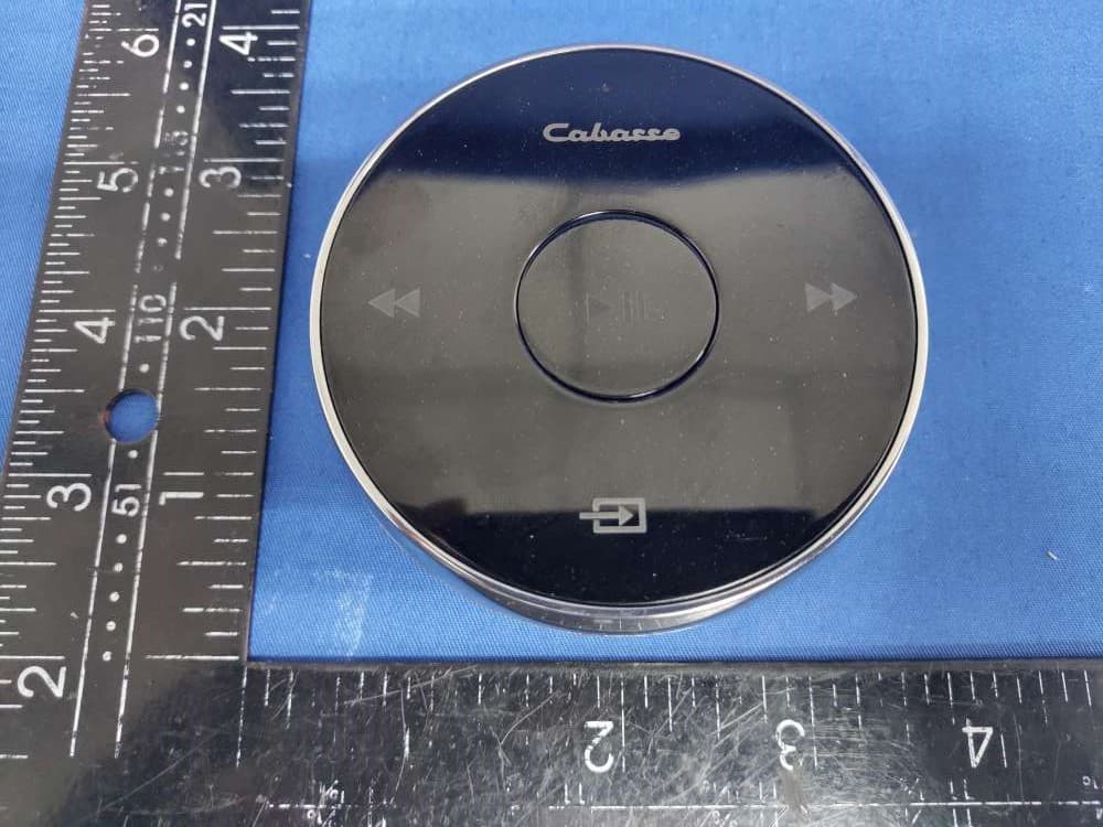
2ACK6-ELC0343
Jun 02, 2021Cabasse Pearl Remote Control
Equipment Class
DTS - Digital Transmission System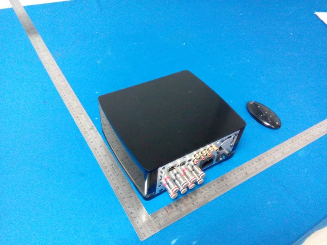
2ACK6AMP100
Nov 17, 2014Amplifier
Equipment Class
DTS - Digital Transmission System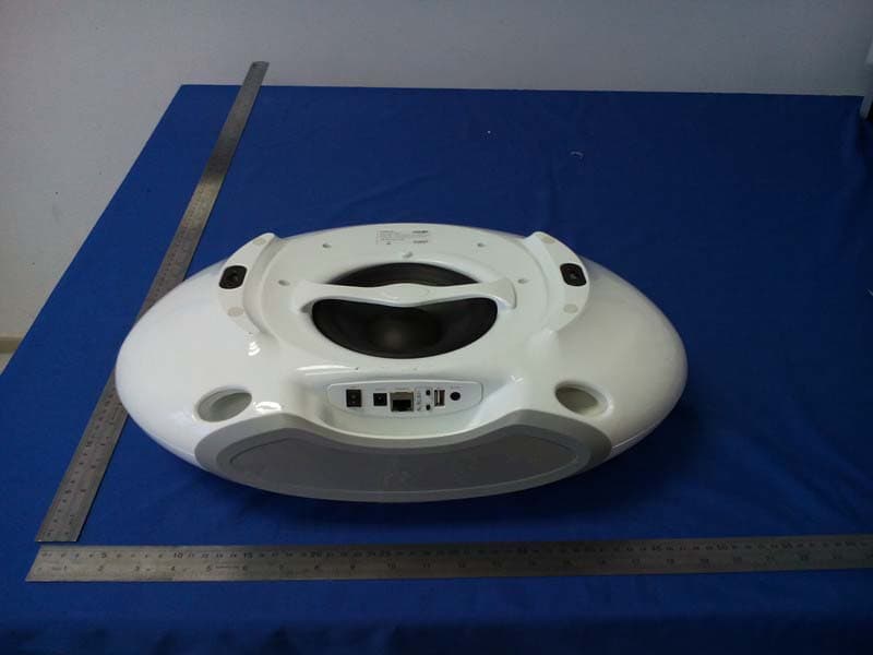
2ACK6STRM1
Jul 03, 2014Active speaker system
Equipment Class
DTS - Digital Transmission System