2ACK6STRM1Active speaker system
CABASSE SA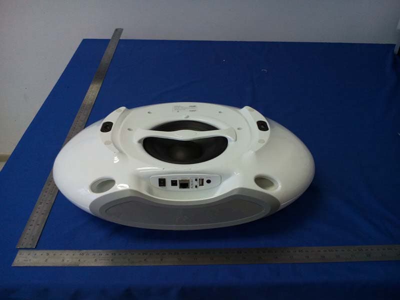
Click to zoom
Application Details
- Equipment Class
- DTS - Digital Transmission System
- Date of Grant
- Jul 03, 2014
- Application Purpose
- Original Equipment
- Date of Application
- Jul 02, 2014
- Equipment Note
- Active speaker system
- Frequency Range
- 2412.00000000 - 2462.00000000
- Company
- CABASSE SA
- Country
- France
Documents & Files
Document Text
Text extracted from the exhibit documents filed with the FCC. Open a document above to read the original.
Users Manual
notice d'installation owner's manual betriebsanleitung stream 1 f r a n c a i se n g l i s hd e u t s c h 2 ---1 ---1 3 IDENTIFICATION DES COMMANDES IDENTIFYING CONTROLS ERKLÄRUNG DER BEDIENELEMENTE 1 LED DISPLAYMARCHE / ECOON / ECOEIN/ECO 2VOL -Diminution du volumeVolume DOWNLautstärke verringern 3VOL +Augmentation du volumeVolume UPLautstärke erhöhen 4 Active et désactive la coupure du sonMute on/offStummschaltung Ein/Aus 8 Selection de la sourceSource selectionQuellenwahl 9 SOURCE LED Rouge: mode ECO Bleu : Bluetooth Orange : Wifi Vert : analogique Red: ECO mode Blue: Bluetooth Orange: Wifi Green: analogue Rot: ECO-Modus Blau: Bluetooth Orange: WLAN Grün: Analog 10Position du patch NFCPosition of the NFC patchPosition des NFC-Patch 11 Position du capteur infra-rouges et du microphone du kit mains-libres Bluetooth Position of the infrared sensor and of the microphone for Bluetooth handsfree use Position des Infrarot-Empfängers und des Mikrofons für die Bluetooth- Freisprecheinrichtung 1 2 5 7 3 4 6 8 IDENTIFICATION DES COMMANDES IDENTIFYING CONTROLS ERKLÄRUNG DER BEDIENELEMENTE 1MARCHE / ECOON / ECOEIN / ECO 2VOL -Diminution du volumeVolume DOWNLautstärke VERRINGERN 3VOL + Augmentation du volume Volume UPLautstärke ERHÖHEN 4 Activation et et désac- tivation de la coupure du son Mute on/offStummschaltung Ein/Aus 5 Wifi : retour rapide Bluetooth : titre précé- dent de l'album lu Wifi: reverse scanning Bluetooth: previous title of the played album WLAN: abwärts scannen Bluetooth: vorheriger Titel des gerade gespielten Albums 6 Wifi : avance rapide Bluetooth : titre sui- vant de l'album lu Wifi: forward scanning Bluetooth: next title of the played album WLAN: aufwärts scannen Bluetooth: nächster Titel des gerade gespielten Albums 7Pause/Lecture Pause/Play Pause/Play 8 Selection de la sourceSource selectionQuellenwahl 10 11 9 FONCTIONS SPECIALES : - REINITIALISATION DU BLUETOOTH : appuyer sur 2 et 3 simultanément - AFFICHAGE DES DIODES : appuyer sur 2 puis sur 8 pour permuter entre l'affichage permanent et le mode flash. KEYPAD SPECIAL FUNCTIONS: - BLUETOOTH RESET: press 2 and 3 together - LED DISPLAY: press 2 then 8 to switch between full time and flash display modes. SPEZIELLE FUNKTIONEN DES TASTENFELDES: - RESET DER BLUETOOT-FUNKTION: Betätigen Sie 2 und 3 gemeinsam - LED-ANZEIGE: Betätigen Sie erst 2 und dann 8 um zwischen kontinuierlichen und blinkenden Modi umzuschalten. 3 8 21 f r a n c a i se n g l i s hd e u t s c h 4 MONTAGE MURAL AVEC TOUCH PAD ET CONNECTIQUE EN BAS WALL MOUNT WITH TOUCH PAD AND CONNECTIONS BOARD DOWN WANDMONTAGE MIT NACH UNTEN WEISENDEM ANSCHLUSSFELD 270 mm 147 mm vis Ø 4mm Ø 4 mm screw Schraube Ø 4mm 270 mm 141 mm vis Ø 4mm Ø 4 mm screw Schraube Ø 4mm MONTAGE MURAL AVEC TOUCH PAD ET CONNECTIQUE EN HAUT WALL MOUNT WITH TOUCH PAD AND CONNECTIONS BOARD UP WANDMONTAGE MIT NACH OBEN WEISENDEM ANSCHLUSSFELD 5 INSTALLATION RAPIDE / QUICK PLUG & PLAY / SCHNELLEINSTIEG Installer votre Stream 1 à proximité d'une prise de courant, soit couché, soit posé debout ou encore accroché au mur. Prévoir un espace suffisant pour le cas échéant pouvoir poser brièvement un smartphone NFC au milieu de la grille du Stream 1 et réaliser une liaison Bluetooth automatique. Cet espace est aussi nécessaire au bon fonctionnement des antennes Bluetooth et wifi. Place the Stream 1 close to a mains plug, either lying, standing or hanging, with enough available headroom above the NFC patch for a smartphone and the use of instant Blutooth connection. This headroom is also necessary for the optimum efficiency of the Bluetooth and wifi antennas. Platzieren Sie das Stream 1 entweder liegend, stehend oder an der Wand hängend in der Nähe einer Steckdose. Achten Sie darauf, dass oberhalb des NFC-Patch genügend Freiraum für ein Smartphone und die Bluetooth-Sofortverbindung bleibt. Dieser Freiraum ist für die optimale Wirkungsweise der Bluetooth-und WLAN-Antennen ebenfalls notwendig. Avant la première utilisation : retirer la languette de protection qui dépasse du couvercle. Remplacement de la pile bouton type CR-2025: retourner la télécommande, enlever le couvercle, enlever la pile usagée, insérer la pile neuve, coté marquée "+" vers l'extérieur, remettre le couvercle. Before first use: remove the battery protection tab to activate the battery. Replacement of the CR-2025 type battery in the Stream remote control: Insert your thumbnail under the clasp and press to realease it, remove the rear lid, remove the old battery and load the new battery properly with the "+" side on the clasp side, put the rear cover back on. Vor der ersten Benutzung der Fernbedienung müssen Sie den Entladeschutz entfernen. Ersetzen der Batterie (Typ CR-2025) bei der Fernbedienung des Stream 1: Entriegeln Sie den Verschluss auf der Rückseite der Fernbedienung mit einem Fingernagel und legen Sie den Deckel beiseite. Entfernen Sie die alte Batterie und platzieren Sie die neue Batterie mit der "+"-Markierung nach außen, so dass sie sichtbar bleibt. Bringen Sie den Deckel wieder an. 3 Connecter l'alimentation externe au Stream 1, brancher l'alimentation au secteur et basculer l'interrupteur marche/ arrêt sur "on". Stream 1 est opérationnel dès que la diode 9 s'allume en rouge (mode ECO). Passer en mode MARCHE en appuyant sur la touche 1 du Stream 1 ou de la télécommande. NOTE : la fonction wifi de Stream 1 devient opérationnelle lorsque la diode PWR (power) est passée du rouge au vert, environ 40 secondes après la mise sous tension. Connect the power supply to the Stream 1, plug it to the mains and position the POWER ON/ OFF switch on "ON". Stream 1 is ready to play when the LED 9 enlights red (ECO mode). Turn the Stream 1 on by pressing the 1 key on the pad or the remote control. NOTE: the wifi mode of Stream 1 is available when the PWR (Power) LED has turned from red to green, around 40 seconds after powering on the Stream 1. Verbinden Sie das Netzteil mit dem Stream 1 und mit einer Steckdose. Bringen Sie den Schalter POWER ON/OFF …
Text truncated - open the document above for the full version.
Cover Letter(s)
SCS-F18: Project and Product Certification Representative Authorization Letter Page 1 of 3 Rev 4.0 775 Montague Expressway Milpitas, CA 95035 Tel: 408-526-1188 Fax: 408-526-1088 Email: [email protected] Project and Product Certification Representative Authorization Letter Revision History Reason for Amendment (current / obsolete) From To Approved Date Initial Release (obsolete) 1.0 1.0 Nov-14-2006 Revised wording (obsolete) 1.0 2.0 Sept–25-2007 Updated company template (obsolete) 2.0 3.0 Jan-31-2012 Updated letter information (current) 3.0 4.0 May-23-2014 SCS-F18: Project and Product Certification Representative Authorization Letter Page 2 of 3 Rev 4.0 CABASSE SA 210. RUE RENE DESCARTES-BP 10,29280 PLOUZANE, FRANCE 2014-6-20 To: SIEMIC, INC. 775 Montague Expressway, Milpitas, CA 95035 USA Dear Sir/Madam, Re: Product Certification Representative Authorization Letter We, CABASSE SA hereby authorize SIEMIC, Inc. to act as a Certification Body for certifying for the following project(s): FCC ID: 2ACK6STRM1 Model:STREAM 1 Sincerely, signature : name / title: KERNEIS David / Electronic engineer address: 210. RUE RENE DESCARTES-BP 10,29280 PLOUZANE, FRANCE Active speaker system SCS-F18: Project and Product Certification Representative Authorization Letter Page 3 of 3 Rev 4.0 CABASSE SA 210. RUE RENE DESCARTES-BP 10,29280 PLOUZANE, FRANCE 2014-6-20 To: SIEMIC, Inc. 775 Montague Expressway, Milpitas, CA 95035 USA Dear Sir/Madam, Re: Project and Product Certification Representative Authorization Letter We, CABASSE SA hereby authorize SIEMIC, Inc. to act as Certification Body for certifying for the following project(s): FCC ID: 2ACK6STRM1 Model:STREAM 1 We affirm that between SIEMIC, Inc. and CABASSE SA , any difference in understanding, including test plan, measurement methods, applicable standards and relevant procedures and processes have been resolved prior to commencement of testing activities. Sincerely, signature : name / title: KERNEIS David / Electronic engineer address: 210. RUE RENE DESCARTES-BP 10,29280 PLOUZANE, FRANCE Active speaker system
Cover Letter(s)
SCS-F19: Confidentiality Request Letter Page 1 of 2 Rev 3.0 775 Montague Expressway Milpitas, CA 95035 Tel: 408-526-1188 Fax: 408-526-1088 Email: [email protected] Confidentiality Request Letter Revision History Reason for Amendment (current / obsolete) From To Approved Date Initial Release (obsolete) 1.0 1.0 Nov-14-2006 Adding CFR 2.459 (obsolete) 1.0 2.0 August – 11 - 2008 Updated company template & Added text box (current) 2.0 3.0 Jan-31-2012 SCS-F19: Confidentiality Request Letter Page 2 of 2 Rev 3.0 CABASSE SA 210. RUE RENE DESCARTES-BP 10,29280 PLOUZANE, FRANCE 2014-6-20 To: Federal Communications Commission Authorization and Evaluation Division 7435 Oakland Mills Road Columbia, MD Subject: Permanent Confidentiality Request for FCC ID: 2ACK6STRM1 We hereby request confidential treatment of information accompanying this application as outlined below: Block Diagram Schematics Operational Description The above materials contain trade secrets and proprietary information not customarily released to the public. The public disclosure of these materials may be harmful to the applicant and provide unjustified benefits to its competitors. The applicant understands that pursuant to Section 0.457 & 0.459 of the Rules, disclosure of this application and all accompanying documentation will not be made before the date of the Grant for this application. Sincerely, signature : name / title: KERNEIS David / Electronic engineer address: 210. RUE RENE DESCARTES-BP 10,29280 PLOUZANE, FRANCE
Cover Letter(s)
CABASSE SA 210. RUE RENE DESCARTES-BP 10,29280 PLOUZANE, FRANCE FCC ID: 2ACK6STRM1 To Whom It May Concern: We, the undersigned, hereby attest to the fact that we will apply the Declaration of Conformity procedure to the class B computer peripheral portion of this composite device. We understand that devices subject to the DoC procedure are required to be tested to show compliance with the FCC technical regulations by a recognized accredited testing laboratory. The testing laboratory must be accredited by a Commission approved accreditation body or designated under the terms of a government-to-government Mutual Recognition Agreement (MRA). A listing of those accredited testing laboratories that have been recognized by the Commission is published on the FCC Test facilities located in countries, where the U.S. does not have an operational Telcom MRA are not recognized by the FCC to test for the DoC procedure. Sincerely, signature : name / title: KERNEIS David / Electronic engineer address: 210. RUE RENE DESCARTES-BP 10,29280 PLOUZANE, FRANCE
ID Label/Location Info
Label location
Internal Photos
WIFI Antenna BT Antenna
RF Exposure Info
FCC ID: 2ACK6STRM1 1. RF EXPOSURE EVALUATION 1.1. Limits The criteria listed in the following table shall be used to evaluate the environment impact of human exposure to radio frequency (RF) radiation as specified in 1.1307(b) Limits for Maximum Permissible Exposure (MPE) f = frequency in MHz Friis transmission formula: Pd = (Pout*G)/(4*pi*r 2 ) Where Pd = power density in mW/cm 2 , Pout = output power to antenna in mW; G = gain of antenna in linear scale, Pi = 3.1416; R = distance between observation point and center of the radiator in cm Pd id the limit of MPE, 1 mW/cm 2 . If we know the maximum gain of the antenna and the total power input to the antenna, through the calculation, we will know the distance r where the MPE limit is reached. 1.2. Test Procedure Software provided by client enabled the EUT to transmit and receive data at lowest, middle and highest channel individually. FCC ID: 2ACK6STRM1 1.3. Test Result of RF Exposure Evaluation Channel Frequency (MHz) Output power to antenna (mW) Antenna Gain(dBi) Power Density at R=20cm (mW/cm 2 ) Limit (mW/cm 2 ) Result 2412 34.43 3.0 0.01367 1.0 Pass 2437 34.36 3.0 0.01364 1.0 Pass 802.11b 2462 33.19 3.0 0.01317 1.0 Pass 2412 17.06 3.0 0.00677 1.0 Pass 2437 16.90 3.0 0.00671 1.0 Pass 802.11g 2462 16.48 3.0 0.00654 1.0 Pass 2412 14.00 3.0 0.00556 1.0 Pass 2437 14.22 3.0 0.00565 1.0 Pass 802.11n (HT20) 2462 13.71 3.0 0.00544 1.0 Pass 2422 13.06 3.0 0.00518 1.0 Pass 2437 12.91 3.0 0.00513 1.0 Pass 802.11n (HT40) 2452 13.00 3.0 0.00516 1.0 Pass
Test Report
FCC ID: 2ACK6STRM1 Keyway Testing Technology Co., Ltd. Report No. 14KWE06156802F Page 1 of 47 FCC TEST REPORT for CABASSE SA Active speaker system Model Number: Stream 1 FCC ID: 2ACK6STRM1 Prepared for : CABASSE SA Address : 210. RUE RENE DESCARTES-BP 10, 29280 PLOUZANE, FRANCE Prepared by : Keyway Testing Technology Co., Ltd. Address : Baishun Industrial Zone, Zhangmutou Town, Dongguan, Guangdong, China Report No. : 14KWE06156802F Date of Test : Jun. 4~14, 2014 Date of Report : Jun. 15, 2014 FCC ID: 2ACK6STRM1 Keyway Testing Technology Co., Ltd. Report No. 14KWE06156802F Page 2 of 47 TABLE OF CONTENTS Test Report Declaration Page 1. TEST SUMMARY .................................................................................................................................4 2. GENERAL PRODUCT INFORMATION ...............................................................................................4 2.1. Product Function...........................................................................................................................4 2.2. Description of Device (EUT) .........................................................................................................4 2.3. Independent Operation Modes .....................................................................................................5 2.4. Test Supporting System................................................................................................................5 3. TEST SITES .........................................................................................................................................6 3.1. Test Facilities ................................................................................................................................6 3.2. List of Test and Measurement Instruments...................................................................................7 4. TEST SET-UP AND OPERATION MODES .........................................................................................8 4.1. Principle of Configuration Selection ..............................................................................................8 4.2. Block Diagram of Test Set-up .......................................................................................................8 4.3. Test Operation Mode and Test Software ......................................................................................8 4.4. Special Accessories and Auxiliary Equipment ..............................................................................8 4.5. Countermeasures to Achieve EMC Compliance...........................................................................8 5. EMISSION TEST RESULTS ................................................................................................................9 5.1. Conducted Emission at the Mains Terminals Test........................................................................9 5.2. Radiated Emission Test ..............................................................................................................11 6. 6DB OCCUPY BANDWIDTH .............................................................................................................28 6.1. Limits...........................................................................................................................................28 6.2. Test setup ...................................................................................................................................28 6.3. Test result ...................................................................................................................................28 7. BAND EDGE COMPLIANCE TEST ...................................................................................................35 7.1. Limits...........................................................................................................................................35 7.2. Test setup ...................................................................................................................................35 8. OUTPUT POWER TEST ....................................................................................................................38 8.1. Limits...........................................................................................................................................38 8.2. Test setup ...................................................................................................................................38 8.3. Test result ...................................................................................................................................38 9. POWER SPECTRAL DENSITY TEST ...............................................................................................39 9.1. Limits...........................................................................................................................................39 9.2. Test setup ...................................................................................................................................39 9.3. Test result ...................................................................................................................................39 10. ANTENNA REQUIREMENTS ..........................................................................................................42 10.1. Limits.........................................................................................................................................42 10.2. Result........................................................................................................................................42 11. PHOTOGRAPHS OF TEST SET-UP ...............................................................................................43 12. PHOTOGRAPHS OF THE EUT .......................................................................................................4…
Text truncated - open the document above for the full version.
Test Setup Photos
Conducted Emission Radiated Emission
Contact Information
Applicant
KERNEIS David
Test Firm
Keyway Testing Technology Co., Ltd.Jade Yang
Technical Specifications
| # | Rule Parts | Frequency Range | Power Output |
|---|---|---|---|
| 1 | 15C | 2.41 GHz - 2.46 GHz | 34.00 mW |
Other Applications from CABASSE SA
2ACK6-ELC0343
Jun 02, 2021Cabasse Pearl Remote Control
Equipment Class
DTS - Digital Transmission System
2ACK6AMP100
Nov 17, 2014Amplifier
Equipment Class
DTS - Digital Transmission System
2ACK6STRM3
Jul 20, 2014Active speaker system
Equipment Class
DTS - Digital Transmission System