2ACQ6-CSCWireless Scene Controller
Ideal Industries Lighting LLC, DBA CREE Lighting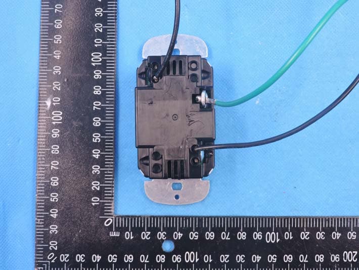
Click to zoom
Application Details
- Equipment Class
- DTS - Digital Transmission System
- Date of Grant
- Feb 09, 2021
- Application Purpose
- Original Equipment
- Date of Application
- Feb 09, 2021
- Equipment Note
- Wireless Scene Controller
- Frequency Range
- 2405.00000000 - 2480.00000000
- Country
- United States
Documents & Files
Document Text
Text extracted from the exhibit documents filed with the FCC. Open a document above to read the original.
Users Manual
LPN00838X0002A0_A 1 of 3 Cree Wireless Scene Controller With SmartCast ® Technology Wireless Scene Controller Includes: CSC-SC-XX INSTALLATION INSTRUCTIONS INSTRUCTIONS D’INSTALLATION IMPORTANT SAFEGUARDS When using electrical equipment, basic safety precautions should always be followed including the following: READ AND FOLLOW ALL SAFETY INSTRUCTIONS 1. Before installing Wireless Scene Controller turn off the power at the circuit breaker. Couper l’alimentation avant l’installation 2. These Wireless Scene Controller must be installed in accordance with the national and local building codes and electrical wiring codes including wiring methods and wiring connections. If you are not familiar with these codes and requirements, consult a Ce produit doit être installé conformément à NEC ou votre code électrique local. Si vous n’êtes pas familier avec ces codes et ces 3. Indoor use only and suitable for damp locations. Pour usage interieur seulement et convient aux emplacements humides. 4. equipment. SAVE THESE INSTRUCTIONS FOR FUTURE REFERENCE UNIT DESCRIPTION The Cree Wireless Scene Controller is used with other SmartCast ® Technology enabled devices to provide wireless preset/scene control of SmartCast- enabled LED luminaires. The Cree Wireless Scene Controller provides default and customizable scene controls for up to 14 control zones. LOAD TYPES Cree Wireless Scene Controller support Cree SmartCast ® Technology enabled devices only. • Voltage: 120-277V, 60Hz • Depth in Wall: 1.5" • For ease of installation, Cree recommends the use of a deep wall • NOT FOR USE WITH METALLIC FACEPLATES. LPN00838X0002A0_A 2 of 3 WIRELESS SCENE CONTROLLER FEATURES • The Cree Scene Controller supports on, off, and dimming controls. See Figure 1. • The Cree Wireless Scene Controller supports on, off, and dimming, and color controls. See Figure 1. • The Cree Wireless Scene Controller provides preset scene control from a single-gang push-button wallstation. • Scenes may be assigned to each of the 5 buttons. See Figure 1. • Preset scenes may assign light levels, color temperatures (CCT), or both. INSTALLATION NOTE: For ease of installation, Cree recommends using a deep wall box. STEP 1: Disconnect power to circuit by turning circuit breaker OFF before installation. STEP 2: If necessary remove existing wall plate and switch. STEP 3: Strip existing wires ½". If two wires will be connected to the same terminal on the Cree device, both wires must be the same gauge (12AWG or 14AWG). STEP 4: Wire the LINE (black), NEUTRAL (white), and GND (green or bare) supply wires to the corresponding pigtail leads on the Cree device, as shown in Figure 2. For Scene controllers with no neutral wire. Wire the LINE IN (black) to supply wires, LINE OUT to the switched power, and GND (green or bare) supply wires to the corresponding pigtails on the Cree device, as shown in Figure 3. NOTE: If replacing an existing wall switch, the Wireless Scene Controller shall be wired as instructed; however, the switched power to the load must also be tied directly to the AC supply leads. STEP 5: Attach the wall plate (reference the wall plate instruction sheet). STEP 6: Switch the circuit breaker ON. STEP 7: Press and release any button. The blue LED should blink twice and then go off. If the blue LED does not respond with the two- blink sequence, please follow the RESET instructions to return the Wireless Scene Controller to factory defaults. NEUT GND LINE SUPPLY LEADS 2 LED LINE GND LINE IN SUPPLY LEADS 3 LINE TO LOAD 120-277VAC 60Hz XX APPLIANCE CONTROLS 18AWG Cu wire Made in China TOP CSC-SC 5NW1 Status LED 1 Button 2 Button 3 Top Button/ Button 1 Button 4 Button 5 WIRELESS SCENE CONTROLLER 120-277VAC 60Hz XX APPLIANCE CONTROLS 18AWG Cu wire Made in China TOP CSC-SC 5NW1 • Type 1 enclosure & IP20 Indoor use • Operating Temperature limit of the control: 0 to 35C • Software Class A Lighting Controls • Pollution degree 2 Suitable for normal household air circulation • Operating Control, Electronic Dimming Switch;• LPN00838X0002A0_A 3 of 3 www.creelighting.com © 2020 Cree Lighting, A company of IDEAL INDUSTRIES. All rights reserved. For informational purposes only. Content is subject to change. See www.creelighting.com/warranty for warranty and specifications. Cree ® and the Cree logo are registered trademarks and the Cree SmartCast Technology logo is a trademark of Cree, Inc. SmartCast ® , is a registered trademark of Cree Lighting, A company of IDEAL INDUSTRIES. RESET WIRELESS SCENE CONTROLLER STEP 1: Press and hold the TOP button on the Wireless Scene Controller for 30s until the LED flashes fast. STEP 2: Briefly release the TOP button for less than 1 second (Fast flashing continues). STEP 3: Press/HOLD the TOP button for 1 second until flashing stops. The LED will then return to the two blink sequence (discovery mode). CLEANING Clean using a cloth dampened only with water and a little mild detergent. Use of solvents or hydrocarbon-based cleaners may cause permanent damage. FCC NOTICE This device complies with Part 15 of the FCC Rules. Operation is subject to the following two conditions: (1) this device may not cause harmful interference, and (2) this device must accept any interference received, including interference that may cause undesired operation. Any changes or modifications not expressly approved by the party responsible for compliance could void the user’s authority to operate the device. This device has been tested and found to comply with the limits for a Class A digital device, pursuant to Part 15 of the FCC Rules. These limits are designed to provide reasonable protection against harmful interference when the device is operated in a commercial environment. This device generates, uses, and can radiate radio frequency energy and, if not installed and used in accordance with the instruction manual, may cause harmful interference to radio communications. Operation of this device in a residential area is likely to cause harmful interferenc…
Text truncated - open the document above for the full version.
Cover Letter(s)
IDEAL INDUSTRIES LIGHTING LLC,DBA CREE LIGHTING Agent Authorization Company: IDEAL INDUSTRIES LIGHTING LLC,DBA CREE LIGHTING Address: 4401 Silicon Drive Durham,NC 27703 USA Product Name: Wireless Scene Controller Model Number(s): CSC-SC-A-5B-UNVN-WH, CSC-SC-A-5B-UNV-WH, CSC-SC-A-5S-UNVN-WH, CSC-SC-A-5C-UNVN-WH, CSC-SC-A-5S-UNV-WH, CSC-SC-A-5C-UNV-WH Product Description: Zigbee Wireless Scene Controller We authorize MiCOM Labs Inc., 575 Boulder Court, Pleasanton, California 94566, USA, to act on our behalf on all matters concerning the certification of above named equipment. We declare that MiCOM Labs Inc. is allowed to forward all information related to the approval and certification of equipment to the regulatory agencies as required and to discuss any issues concerning the approval application. Any and all acts carried out by MiCOM Labs on our behalf shall have the same effect as acts of our own. Signature: Date: 2021/02/01 Name: Samir Syal Title: Compliance Engineering Manager Company: IDEAL INDUSTRIES LIGHTING LLC,DBA CREE LIGHTING
Cover Letter(s)
IDEAL INDUSTRIES LIGHTING LLC,DBA CREE LIGHTING Authorization Letter We, (the approval holder) Company name IDEAL INDUSTRIES LIGHTING LLC,DBA CREE LIGHTING Addresss 4401 Silicon Drive Durham,NC 27703 USA declare that the following representative (agent): Name (person) Bovey Yang Company name Shenzhen STS Test Services Co., Ltd. Addresss 1/F., Building B, Zhuoke Science Park, No.190, Chongqing Road, Fuyong Street, Bao’an District, Shenzhen, Guangdong,China City Shenzhen Country China to act on our behalf on all matters concerning the application and documents submitted to Micom Labs for product certification below Product Description Wireless Scene Controller Type or Model(s) CSC-SC-A-5B-UNVN-WH, CSC-SC-A-5B-UNV-WH, CSC-SC-A-5S-UNVN-WH, CSC-SC-A-5C-UNVN-WH, CSC-SC-A-5S-UNV-WH, CSC-SC-A-5C-UNV-WH Tradename or Brand(s) Attestation: City: Date: Name: (this must be a person) Function: Signature: (or official company stamp) China 2021/02/01 Samir Syal Compliance Engineering Manager
Cover Letter(s)
Differences Description We IDEAL INDUSTRIES LIGHTING LLC,DBA CREE LIGHTINGstate: Product: Wireless Scene Controller Model Name: CSC-SC-A-5B-UNVN-WH, CSC-SC-A-5B-UNV-WH, CSC-SC-A-5S-UNVN-WH, CSC-SC-A-5C-UNVN-WH, CSC-SC-A-5S-UNV-WH, CSC-SC-A-5C-UNV-WH Brand Name: FCC ID: 2ACQ6-CSC IC: 11481A-CSC The electrical circuit design, layout, components used, and internal wiring are identical, there're 2 pcs power supply board used (same electrical circuit design, and layout difference). The difference of each number of buttons and appearance. Sincerely, Company: IDEAL INDUSTRIES LIGHTING LLC,DBA CREE LIGHTING Title: Compliance Engineering Manager E-mail: [email protected] Name: Samir Syal Signature
Cover Letter(s)
IDEAL INDUSTRIES LIGHTING LLC,DBA CREE LIGHTING Office of Engineering Technology Federal Communications Commission 7435 Oakland Mills Road Columbia, MD 21046 USA Date: 2021/02/01 Subject; Request for Confidentiality FCC ID: 2ACQ6-CSC To Whom It May Concern, Pursuant to the provisions of the Commission’s rules Title 47 Sections §0.457 and §0.459, we are requesting the Commission to withhold the following attachment(s) as confidential documents from public disclosure indefinitely. These documents contain detailed system and equipment descriptions and are considered as proprietary information in operation of the equipment. The public disclosure of these documents might be harmful to our company and would give competitors an unfair advantage in the market. Schematic Diagram Block Diagram Parts List Operational Description Tune-up Procedure In additional to above mentioned documents, in order to comply with the marketing regulations in Title 47 CFR §2.803 and the importation rules in Title 47 CFR §2.1204, while ensuring that business sensitive information remains confidential until the actual marketing of newly authorized devices, we request Short Term Confidentiality of the following attachment(s); External Photos Test Setup Photos Internal Photos User Manual For 45 days, pursuant to Public Notice DA 04-1705. OR For 180 days pursuant to KDB 726920 D01. It is our understanding that all measurement test reports, FCC ID label format and correspondence during the certification review process cannot be granted as confidential documents and this information will be available for public review once the grant of equipment authorization is issued. Sincerely, Signature: Name: Samir Syal Title: Compliance Engineering Manager
External Photos
4789677056.2.2-A2 4789677056.2.2-A2 4789677056.2.2-A2
ID Label/Location Info
MODEL:Wireless Scene Controller FCC ID:2ACQ6-CSC IC:11481A-CSC Input: Location silk screen 30mm * 30mm 120VAC
Internal Photos
4789677056.2.2-A2 View of power supply board for CSC-SC-A-5B-UNVN-WH 4789677056.2.2-A2 View of power supply board for CSC-SC-A-5B-UNV-WH 4789677056.2.2-A2 View of module 4789677056.2.2-A2
RF Exposure Info
RF Exposure Report FCC ID: 2ACQ6-CSC RF Exposure Measurement The limit for Maximum Permissible Exposure (MPE) specified in FCC 1.1310 is followed. The gain of the antennas used in the product is extracted from the Antenna data sheets provided and also the maximum total power input to the antenna is measured. Through the Friis transmission formula and the maximum gain of the antenna, we can calculate the distance, away from the product, where the limit of MPE is reached. Although the Friis Transmission formula is far field assumption, the calculated result of that is an over-prediction for near field power density. It is taken as worst case to specify the safety range. RF Exposure Limit According to FCC 1.1310: The criteria listed in the following table shall be used to evaluate the environmental impact of the human exposure to radio-frequency (RF) radiation as specified in 1.1307 (b) Limits for Maximum Permissible Exposure (MPE) F= Frequency in MHz Frequency Range (MHz) Electric Field Strength (V/m) Magnetic Field Strength (A/m) Power Density (mW/cm²) Limits for Occupational / controlled Exposures 300 - 1500 -- -- F/300 1500 – 100000 -- -- 5.0 Limits for General population / Uncontrolled Exposure 300 - 1500 -- -- F/1500 1500 – 100000 -- -- 1.0 Friss Formula Friss Transmission Formula: Pd = (Pout * G) / (4*pi*r²) Where Pd = power density in mW/cm² Pout = output power to antenna in mW G = gain of antenna in linear scale Pi = 3.1416 R = Distance between observation point and the center of radiator in cm If we know the maximum gain of the antenna and the total output power to the antenna, through calculation, we will know MPE value at distance 20cm. EUT Operation condition EUT was enabled to transmit and receive at lowest, middle and highest channels. Classification The antenna of this product, under normal use condition, is at least 20cm away from the body of the user. Warning statement to the user for keeping at least 20cm or more separation distance from the antenna should be included in the User manual. So, this device is classified as Mobile device. Zigbee Mode 2405-2480MHz Detector PEAK OQPSK 1±1dBm ANT Gain (G) Antenna gain : -0.5dBi (gain of antenna in linear scale=0.891) GFSK 0.891 2480 2 1.5849 0.00028 1 Power Density (mW/cm²) Limit (mW/cm ²) Protocol ANT Gain(gain of antenna in linear scale) Channel Frequenc y (MHz) Output Power to Antenna (dBm) Output Power to Antenna (mW) According to the maximum gain of the antenna and the total output power to the antenna, through calculation, we will know MPE value 0.00028 distance 20cm. This is less than the limit 1, so compliance the RF exposure requirement..
Test Report
The results reported herein have been performed in accordance with the laboratory’s terms of accreditation. This report shall not be reproduced except in full without the written approval of the Laboratory. The results in this report apply to the test sample(s) mentioned above at the time of the testing period only and are not to be used to indicate applicability to other similar products. This report does not imply that the product(s) has met the criteria for certification. FCC PART 15 SUBPART C ISED RSS-247 ISSUE 2 CERTIFICATION TEST REPORT For Wireless Scene Controller MODEL NUMBER: CSC-SC-A-5B-UNVN-WH, CSC-SC-A-5B-UNV-WH FCC ID: 2ACQ6-CSC IC: 11481A-CSC REPORT NUMBER: 4789677056.2.2 ISSUE DATE: 02 Feb. 2021 Prepared for IDEAL INDUSTRIES LIGHTING LLC,DBA CREE LIGHTING 4401 Silicon Drive Durham,NC 27703 USA Prepared by UL Verification Services (Guangzhou) Co., Ltd, Song Shan Lake Branch Room 101, Building 10, Innovation Technology Park, Song Shan Lake Hi tech Development Zone, Dongguan, 523808, China Tel: +86 769 33817100 Fax: +86 769 33244054 Website: www.ul.com REPORT NO.: 4789677056.2.2 Page 2 of 53 UL Verification Services (Guangzhou) Co., Ltd, Song Shan Lake Branch FORM NO: 10-SL-F0035 This report shall not be reproduced except in full, without the written approval of UL Verification Services (Guangzhou) Co., Ltd, Song Shan Lake Branch. Revision History Rev. Issue Date Revisions Revised By -- 02/02/2021 Initial Issue -- REPORT NO.: 4789677056.2.2 Page 3 of 53 UL Verification Services (Guangzhou) Co., Ltd, Song Shan Lake Branch FORM NO: 10-SL-F0035 This report shall not be reproduced except in full, without the written approval of UL Verification Services (Guangzhou) Co., Ltd, Song Shan Lake Branch. Summary of Test Results Clause Test Items FCC/IC Rules Test Results 1 6dB Bandwidth and 99% Occupied Bandwidth FCC Part 15.247 (a) (2) RSS-247 Clause 5.2 (a) RSS-Gen Clause 6.7 Pass 2 Peak Conducted Output Power FCC Part 15.247 (b) (3) RSS-247 Clause 5.4 (d) Pass 3 Power Spectral Density FCC Part 15.247 (e) RSS-247 Clause 5.2 (b) Pass 4 Conducted Band edge And Spurious emission FCC Part 15.247 (d) RSS-247 Clause 5.5 Pass 5 Radiated Bandedge and Spurious Emission FCC Part 15.247 (d) FCC Part 15.209 FCC Part 15.205 RSS-247 Clause 5.5 RSS-GEN Clause 8.9 Pass 6 Conducted Emission Test For AC Power Port FCC Part 15.207 RSS-GEN Clause 8.8 Pass 7 Antenna Requirement FCC Part 15.203 RSS-GEN Clause 6.8 Pass REPORT NO.: 4789677056.2.2 Page 4 of 53 UL Verification Services (Guangzhou) Co., Ltd, Song Shan Lake Branch FORM NO: 10-SL-F0035 This report shall not be reproduced except in full, without the written approval of UL Verification Services (Guangzhou) Co., Ltd, Song Shan Lake Branch. TABLE OF CONTENTS 1. ATTESTATION OF TEST RESULTS .............................................................................. 5 2. TEST METHODOLOGY .................................................................................................. 6 3. FACILITIES AND ACCREDITATION .............................................................................. 6 4. CALIBRATION AND UNCERTAINTY ............................................................................ 7 4.1. MEASURING INSTRUMENT CALIBRATION ........................................................... 7 4.2. MEASUREMENT UNCERTAINTY ............................................................................ 7 5. EQUIPMENT UNDER TEST ........................................................................................... 8 5.1. DESCRIPTION OF EUT............................................................................................ 8 5.2. MAXIMUM OUTPUT POWER ................................................................................... 8 5.3. CHANNEL LIST ........................................................................................................ 8 5.4. TEST CHANNEL CONFIGURATION ........................................................................ 8 5.5. THE WORSE CASE POWER SETTING PARAMETER ........................................... 8 5.6. DESCRIPTION OF AVAILABLE ANTENNAS ........................................................... 9 5.7. WORST-CASE CONFIGURATIONS ........................................................................ 9 5.8. DESCRIPTION OF TEST SETUP ........................................................................... 10 6. MEASURING INSTRUMENT AND SOFTWARE USED ............................................... 11 7. MEASUREMENT METHODS ........................................................................................ 12 8. ANTENNA PORT TEST RESULTS .............................................................................. 13 8.1. ON TIME AND DUTY CYCLE ................................................................................. 13 8.2. 6 dB BANDWIDTH & 99% BANDWIDTH ................................................................ 15 8.3. PEAK CONDUCTED OUTPUT POWER ................................................................ 20 8.4. POWER SPECTRAL DENSITY .............................................................................. 21 8.5. CONDUCTED BANDEDGE AND SPURIOUS EMISSIONS ................................... 24 9. RADIATED TEST RESULTS ........................................................................................ 29 9.1. LIMITS AND PROCEDURE .................................................................................... 29 9.2. RESTRICTED BANDEDGE .................................................................................... 35 9.3. SPURIOUS EMISSIONS 30MHz-1GHz .................................................................. 39 9.4. SPURIOUS EMISSIONS Above 1 GHz .................................................................. 42 9.5. SPURIOUS EMISSIONS BELOW 30M ................................................................... 46 10. AC POWER LINE CONDUCTED EMISSIONS .......................................................... 47 11. ANTENNA…
Text truncated - open the document above for the full version.
Test Setup Photos
4789677056.2.2-A1 Conducted Emission Radiated Spurious Emission Below 1GHz 4789677056.2.2-A1 Radiated Spurious Emission Above 1GHz
Contact Information
Applicant
Samir Syal(Compliance Engineering Manager)
Technical Contact
Test Firm
SHENZHEN STS TEST SERVICES CO.,LTD.Bovey Yang
[email protected]+86 755-36886288
Technical Specifications
| # | Rule Parts | Frequency Range | Power Output |
|---|---|---|---|
| 1 | 15C | 2.40 GHz - 2.48 GHz | 1.28 mW |
Other Applications from Ideal Industries Lighting LLC, DBA CREE Lighting
2ACQ6-CWC
Aug 23, 2014WALL SWITCH
Equipment Class
DTS - Digital Transmission System
2ACQ6-CIF
Aug 20, 2014Relay Module
Equipment Class
DTS - Digital Transmission System
2ACQ6-CCT
Aug 16, 20142.4 GHz Transceiver
Equipment Class
DTS - Digital Transmission System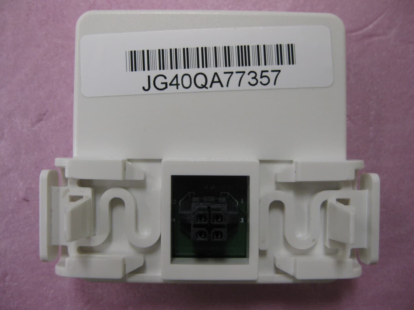
2ACQ6-RFM
Jul 22, 2014RFM MODULE
Equipment Class
DTS - Digital Transmission System