2ACQ6-RFMRFM MODULE
Ideal Industries Lighting LLC, DBA CREE Lighting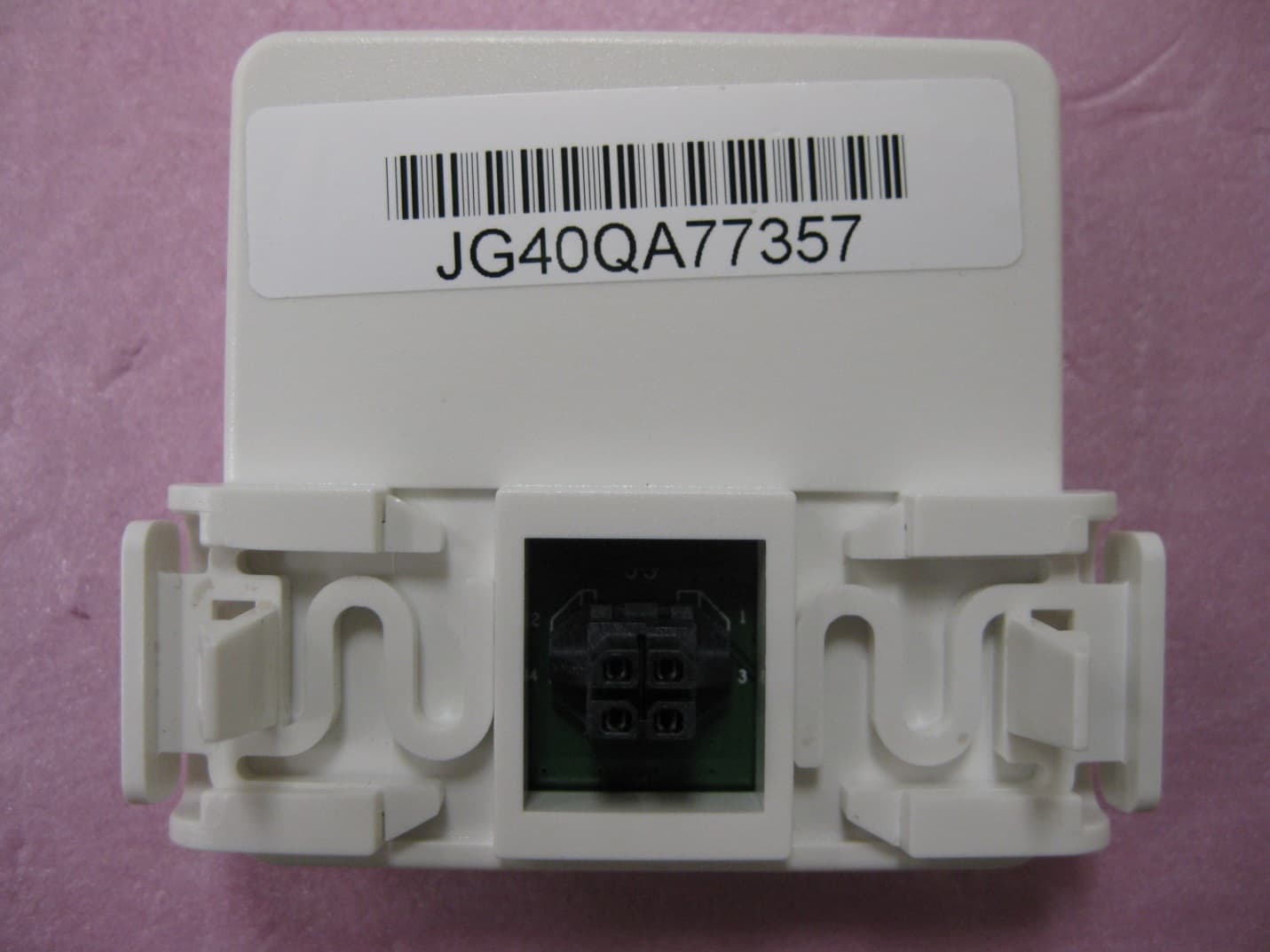
Click to zoom
Application Details
- Equipment Class
- DTS - Digital Transmission System
- Date of Grant
- Jul 22, 2014
- Application Purpose
- Original Equipment
- Date of Application
- Jul 22, 2014
- Equipment Note
- RFM MODULE
- Frequency Range
- 2405.00000000 - 2480.00000000
- Country
- United States
Documents & Files
Document Text
Text extracted from the exhibit documents filed with the FCC. Open a document above to read the original.
Users Manual
CR Series with Cree SmartCast™ Technology CR14™, CR24™, CR22™ LED Architectural Troffers 1x4, 2x4, 2x2 Luminaires 1 of 3LPN00212X0002A7 INSTALLATION INSTRUCTIONS INSTRUCTIONS D’INSTALLATION IMPORTANT SAFEGUARDS When using electrical equipment, basic safety precautions should always be followed including the following: READ AND FOLLOW ALL SAFETY INSTRUCTIONS 1. DANGER- Risk of shock- Disconnect power before installation. DANGER – Risque de choc – Couper l’alimentation avant l’installation. 2. This luminaire must be installed in accordance with the NEC or your local electrical code. If you are not familiar with these codes and requirements, consult a qualified electrician. Ce produit doit être installé conformément à NEC ou votre code électrique local. Si vous n’êtes pas familier avec ces codes et ces exigences, veuillez contacter un électricien qualifié. 3. Do not handle energized module with wet hands or when standing on wet or damp surfaces, or in water. 4. Suitable for damp locations. Convient aux emplacements humides. 5. Access above ceiling required. Do not install insulation within 3" (76mm) of any part of the luminaire. Accès requis au-dessus du plafond. Ne pas mettre l’isolant à moins de 76 mm (3 po) de toute partie du luminaire. 6. Suitable for suspended ceilings. SAVE THESE INSTRUCTIONS FOR FUTURE REFERENCE TO INSTALL: LUMINAIRE INSTALLATION STEP 1: Unpack the CR troffer from its shipping container. STEP 2: Install the (4) T-Bar clips included with the luminaire (located in pre-pack fastened to luminaire junction box). See Figure 1. 1 • The CR Series of recessed troffers is for non-insulated ceiling applications using T-Bar ceiling grid and drywall grid adaptors. • Designed for use in 120-277V 50-60 Hertz protected circuit (fuse box, circuit breaker). Supply wire sized as per NEC or governing code(s), 90° C rated. CR14 CR24 CR22 2 of 3LPN00212X0002A7 STEP 3: Place the CR troffer into the T-Bar Ceiling panel. Ensure T-Bar clips are attached to the T-Bar. See Figure 2. STEP 4: Remove access plate from junction box. Using screw driver blade, remove appropriate knockout from access plate door to route input conduit. See Figure 3. STEP 5: Connect input conduit to access plate. Make wiring connections per Electrical Connections section. Push all wires back into the junction box. STEP 6: Re-install access plate that was removed in Step 4. RESET RF MODULE NOTE: The Blue LED is located behind the CREE logo on the RF Module. The CREE logo with illuminate blue when the Blue LED is active. STEP 1: Actuate RESET button through the access hole. Push and hold until LED on RF module begins blinking rapidly (approximately 6-7 seconds). See Figure 4. STEP 2: Release for 1 sec. STEP 3: Press/Hold RESET button for 0.5 sec. Light will turn off for a few seconds then go to full bright and the Blue LED on the RF Module should begin a 2 blink sequence. Figure 4. TROUBLESHOOTING: Out of the box, if the light does not turn on when power is applied: • Check Wiring with power off • If wired correctly, check to see if Blue LED blinking on the RF Module. • If Blue LED is blinking, then perform a RESET (See RESET RF MODULE section). • If Blue LED is on solid or off, call Cree Customer Service. • If you have done a RESET, and the light is still off, call Cree Customer Service. If light is unresponsive, use Cree Configuration Tool to verify configuration. 3 4 Access Plate RF Module RF Module Access Hole, Reset Button Inside Blue LED Placement 2 3 of 3LPN00212X0002A7 ELECTRICAL CONNECTIONS STEP 1: Make the following Electrical Connections : a. Connect the black fixture lead to the voltage supply position. b. Connect the white fixture lead to the neutral supply position. c. Connect the green ground lead to the green wire position. LINE DRIVER ASSEMBLY BLACK WHITE NEUTRAL FCC NOTICE To comply with the FCC RF exposure compliance requirements, this device and its antenna must not be co-located or operating to conjunction with any other antenna or transmitter. This equipment should be installed and operated with minimum distance 5cm between the radiator & your body. FCC COMPLIANCE STATEMENT CAUTION: Changes or modifications not expressly approved could void your authority to use this equipment. This device complies with Part 15 of the FCC Rules. Operation to the following two conditions: (1) This device may not cause harmful interference, and (2) this device must accept any interference received, including interference that may cause undesired operation This device has been tested and found to comply with the limits for a Class A digital device, pursuant to Part 15 of the FCC Rules. These limits are designed to provide reasonable protection against harmful interference when the device is operated in a commercial environment. This device generates, uses, and can radiate radio frequency energy and, if not installed and used in accordance with the instruction manual, may cause harmful interference to radio communications. Operation of this device in a residential area is likely to cause harmful interference in which case the user will be required to correct the interference at his own expense. The LED in the front of this device operates within Risk Group 1 levels per IEC 62471. INDUSTRY CANADA STATEMENT This device complies with Industry Canada licence-exempt RSS standard(s). Operation is subject to the following two conditions: (1) this device may not cause interference, and (2) this device must accept any interference, including interference that may cause undesired operation of the device. In addition, this device complies with ICES-003 of the Industry Canada (IC) Regulations. Le présent appareil est conforme aux CNR d’Industrie Canada applicables aux appareils radio exempts de licence. L’exploitation est autorisée aux deux conditions suivantes : (1) l’appareil ne doit pas produire de brouillage, et (2) l’utilisateur de l’appareil doit accepter tout brouillage radioélectrique subi, même si le brouillage est suscepti…
Text truncated - open the document above for the full version.
Users Manual
1 of 4LPN00212X0003A7 CS Series With Cree SmartCast™ Technology CS14™, CS18™ LED Linear Luminaire 8' and 4' Luminaires INSTALLATION INSTRUCTIONS INSTRUCTIONS D’INSTALLATION • The CS Series LED linear luminaire is for suspended, with cable or threaded rod, or surface mount applications using appropriate tong hangers. Reference individual mounting accessory installation instructions for specific mounting types. • Designed for use in 120–277V, 50-60 Hertz protected circuit (fuse box, circuit breaker) and supply wire shall be rated minimum 12AWG, 600V, 90 C rated). TO INSTALL: NOTE: When removing luminaire from packaging, keeping protective plastic wrap on fixture during installation and construction. FOR PLASTIC TONG HANGERS (TM): NOTE: Center hole can accommodate 1/2" diameter rod maximum. STEP 1: Remove cross brace and securely insert it into the “+” shaped openings in the plastic tong hanger. See Figures 1 & 2. For single units or end row fixtures, place the plastic tong hanger assembly into center spine no more than 18" from each end of fixture and twist approximately 45 degrees until the plastic tong hanger assembly is securely in place and approximately 90 degrees to the length of fixture. See Figure 3. STEP 2: For continuous row installation, continue with next fixture using a minimum of one tong hanger per unit. Each bracket should be properly snug and be difficult to slide along the back spine. 1 2 Cross Brace Cross Brace IMPORTANT SAFEGUARDS When using electrical equipment, basic safety precautions should always be followed including the following: READ AND FOLLOW ALL SAFETY INSTRUCTIONS 1. DANGER- Risk of shock- Disconnect power before installation. DANGER – Risque de choc – Couper l’alimentation avant l’installation. 2. This luminaire must be installed in accordance with the NEC or your local electrical code. If you are not familiar with these codes and requirements, consult a qualified electrician. Ce produit doit être installé conformément à NEC ou votre code électrique local. Si vous n’êtes pas familier avec ces codes et ces exigences, veuillez contacter un électricien qualifié. 3. Check to make sure that all the fixture connections have been properly made and the fixture is grounded to avoid potential electrical shocks. 4. Do not handle energized module with wet hands or when standing on wet or damp surfaces, or in water. 5. Suitable for damp locations. Convient aux emplacements humides. SAVE THESE INSTRUCTIONS FOR FUTURE REFERENCE WARNING - Maximum connected load with a single power supply shall not exceed maximum ampacity rating of #12 AWG THHN through-wire conductors. Use only lighting controls with relay or FET-based outputs, or lighting controls with neutral connection. Reference www.cree.com/ lighting for recommended dimming control options. Avoid handling LEDs directly. Not intended for use in environments containing airborne corrosive agents such as chemical solvents, cleaners, or cutting fluids 2 of 4LPN00212X0003A7 FOR OPTIONAL METAL TONG HANGERS (TMM): NOTE: Center hole can accommodate 3/8" diameter rod maximum. Recommended for surface mount installations. STEP 1: For single units or end row fixtures, place metal tong hanger bracket over center spine no more than 18" from each end of fixture. See Figure 3. Insert supplied bolt through the metal tong hanger and secure with lock washer and nut, tightening to secure spine to the metal tong hanger. See Figure 4 & 5. Additional suspension points are optional depending on field conditions. STEP 2: For continuous row installation, continue with next fixture using a minimum of one tong hanger per unit. Each bracket should be properly snug and be difficult to slide along the back spine. FOR SUSPENDED MOUNTING: STEP 1: For suspended individual mount luminaires, one Power Feed with Cable Support and one Cable Support is required. STEP 2: For continuous row installation, begin row (luminaire #1) with one Power Feed with Cable Support and one Cable Support. Each subsequent luminaire, one Cable Support is required; not to exceed 18" from end of luminaire. For environments that do not allow proper spacing of cable support, Unistrut may be required, supplied by others. ELECTRICAL CONNECTIONS STEP 1: For powering the fixture(s), open wiring compartment swing door on end of the luminaire and extend wiring in preparation for connections. See Figure 6. STEP 2: Bring AC feed into wiring compartment through conduit hole on left side. Remove black connector and terminate leads according to local codes. STEP 3: Make electrical connections referring to Figure 7. STEP 4: Close swing door assuring no leads are pinched. See Figure 6. LINE DRIVER ASSEMBLY BLACK WHITE NEUTRAL AC Power Compartment Knockout 6 7 18"18" 3 4 5 3 of 4LPN00212X0003A7 ELECTRICAL CONNECTIONS FOR CONNECTING MULTIPLE LUMINAIRES TOGETHER: STEP 1: Attach two fixtures together with screws & nuts provided. See Figure 8. STEP 2: Remove endcap cover of first fixture to reveal through-wiring plug. Open swing door of connecting fixture and remove knockout and extend wiring in preparation for connections. See Figure 9. STEP 3: Carefully feed AC and dimming plugs into wiring compartment through knockout opening. Remove black connector and terminate leads according to local codes. STEP 4: Connect male and female AC connectors. See Figure 10. STEP 5: Tuck lead ferrite into far AC wiring compartment as shown in Figure 10. STEP 6: Place AC connector assembly flat into AC wiring compartment as shown in Figure 11. STEP 7: Close swing door assuring no leads are pinched. Continue powering fixtures until entire row is complete. STEP 8: Remove protective plastic wrap and wire tie from center stiffener. 8 9 10 AC Connector Ferrite AC Connectors AC Wiring Compartment 11 4 of 4LPN00212X0003A7 © 2014 Cree, Inc. All rights reserved. For informational purposes only. Content is subject to change. See www.cree.com/lighting/ products/warranty for warranty and specifications. Cree®, and the Cree logo…
Text truncated - open the document above for the full version.
Users Manual
INSTALLATION INSTRUCTIONS CM-CWC-1 Cree SmartCast™ Technology Wireless Control Module Replacement Kit Includes: CR Series and CS Series LPN00243X0001A0_C 1 of 2 IMPORTANT SAFEGUARDS When using electrical equipment, basic safety precautions should always be followed including the following: READ AND FOLLOW ALL SAFETY INSTRUCTIONS 1. Before installing turn off the power at the circuit breaker. 2. Any changes or modifications to these devices not explicitly approved by manufacturer could void your authority to operate this equipment. SAVE THESE INSTRUCTIONS FOR FUTURE REFERENCE 1 2 Cree Logo Cree Logo STEP 1: Turn power off and remove old control module from luminaire by pressing the clips located on both sides of control module inward and pull control module out from luminaire. NOTE: For location of the control module reference Figure 1 for CR luminaires and Figure 2 for CS luminaires. STEP 2: Orient the new control module so that the Cree logo is in the lower left corner. Attach the new control module to the CR or CS luminaire by pressing in on the clips located on the sides of the control module and inserting it into the designated connector. STEP 3: Turn power on. The new control module is correctly installed if the Blue LED displays a 2 blink sequence. NOTE: If the blue LED does not respond with the two-blink sequence, please follow the RESET instructions to return the control module to factory defaults. STEP 4: On the Configuration Tool, select “Replace Devices” from the “Advanced” menu and follow the on-screen directions.. This will remove old device(s) from the network and add the new device(s). RESET NOTE: The Blue LED is located behind the Cree logo on the control module. The Cree logo with illuminate blue when the Blue LED is active. STEP 1: Actuate RESET button through the test hole. Push and hold (approximately 10 sec), LED on control module will blink fast. STEP 2: Release for 1 sec. STEP 3: Press/Hold RESET button for 0.5 sec. Light will go to full bright and the Blue LED on the control module should be in a 2 blink sequence. TO INSTALL: LPN00243X0001A0_C 2 of 2 www.cree.com/lighting © 2014 Cree, Inc. All rights reserved. For informational purposes only. Content is subject to change. See www.cree.com/lighting/products/warranty for warranty and specifications. Cree® and the Cree logo are registered trademarks, and SmartCast™ is a trademark of Cree, Inc. FCC NOTICE To comply with the FCC RF exposure compliance requirements, this device and its antenna must not be co-located or operating to conjunction with any other antenna or transmitter. This equipment should be installed and operated with minimum distance 5cm between the radiator & your body. No other antenna is authorized for use with this product. FCC COMPLIANCE STATEMENT CAUTION: Changes or modifications not expressly approved could void your authority to use this equipment. This device complies with Part 15 of the FCC Rules. Operation to the following two conditions: (1) This device may not cause harmful interference, and (2) this device must accept any interference received, including interference that may cause undesired operation This device has been tested and found to comply with the limits for a Class A digital device, pursuant to Part 15 of the FCC Rules. These limits are designed to provide reasonable protection against harmful interference when the device is operated in a commercial environment. This device generates, uses, and can radiate radio frequency energy and, if not installed and used in accordance with the instruction manual, may cause harmful interference to radio communications. Operation of this device in a residential area is likely to cause harmful interference in which case the user will be required to correct the interference at his own expense. The LED in the front of this device operates within Risk Group 1 levels per IEC 62471. INDUSTRY CANADA STATEMENT This device complies with Industry Canada licence-exempt RSS standard(s). Operation is subject to the following two conditions: (1) this device may not cause interference, and (2) this device must accept any interference, including interference that may cause undesired operation of the device. In addition, this device complies with ICES-003 of the Industry Canada (IC) Regulations. Le présent appareil est conforme aux CNR d’Industrie Canada applicables aux appareils radio exempts de licence. L’exploitation est autorisée aux deux conditions suivantes : (1) l’appareil ne doit pas produire de brouillage, et (2) l’utilisateur de l’appareil doit accepter tout brouillage radioélectrique subi, même si le brouillage est susceptible d’en compromettre le fonctionnement.
Cover Letter(s)
9201 Washington Avenue, Racine, WI 53406 USA Main: (262) 886-1900 Federal Communications Commission Authorization and Evaluation Division 7435 Oakland Mills Rd. Columbia, MD 21046 Fax: (310) 344-2050 Reference FCC ID: 2ACQ6-RFM Organization: CREE INC. Subject: Request under 47 CFR 0.457 and 0.459 that materials submitted to the commission be withheld from public inspection. CREE INC. hereby requests that the materials attached here to be withheld from public inspection in accordance with 47 CFR 47 0.457 and 0.459. Specifically, CREE INC. requests that the following materials be withheld from public inspection under 47 CFR 0.457 and 0.459 because the schematics and designs are considered confidential trade secrets and technical data which customarily would be guarded from competitors: Schematic Diagram Block Diagram Theory of Operation Therefore, in accordance with CFR 47 0.457 and 0.459, CREE INC. requests that the above listed materials, copies of which are here, to be withheld from public inspection. Authorized Signature: Date: 2014/05/06 Dan Guillien Compliance Manager Cree, Inc.
Cover Letter(s)
Applicant/Grantee Cree Inc. (2ACQ6) FCC ID: 2ACQ6-RFM Section 15.212 Modular Transmitters Request for Modular Approval Request for Limited Modular Approval Requirements EUT Conditions Comply (Y/N) Single Modular Approval Requirements 1 The radio elements of the modular transmitter must have their own shielding. The physical crystal and tuning capacitors may be located external to the shielded radio elements. The RFM radio contains its own shield. Refer to ‘10015043 Internal Photos.PDF’ document. Y 2 The modular transmitter must have buffered modulation/data inputs (if such inputs are provided) to ensure that the module will comply with Part 15 requirements under conditions of excessive data rates or over-modulation. The modular transmitter does have buffered data inputs to ensure that the module complies with Part 15 requirements under conditions of excessive data rates or over-modulation. Buffered modulation is not require because modulation is handled on chip. Y 3 The modular transmitter must have its own power supply regulation. The modular transmitter does have its own power supply regulation. Y 4 The modular transmitter must comply with the antenna and transmission system requirements of Sections 15.203, 15.204(b) and 15.204(c). The antenna must either be permanently attached or employ a “unique” antenna coupler (at all connections between the module and the antenna, including the cable). The “professional installation” provision of Section 15.203 is not applicable to modules but can apply to limited modular approvals under paragraph (b) of this section. The RFM antenna is a permanent PCB trace antenna. Y Applicant/Grantee Cree Inc. (2ACQ6) FCC ID: 2ACQ6-RFM Section 15.212 Modular Transmitters Request for Modular Approval Request for Limited Modular Approval Requirements EUT Conditions Comply (Y/N) Single Modular Approval Requirements 5 The modular transmitter must be tested in a stand-alone configuration, i.e., the module must not be inside another device during testing for compliance with Part 15 requirements. Unless the transmitter module will be battery powered, it must comply with the AC line conducted requirements found in Section 15.207. AC or DC power lines and data input/output lines connected to the module must not contain ferrites, unless they will be marketed with the module (see Section 15.27(a)). The length of these lines shall be the length typical of actual use or, if that length is unknown, at least 10 centimeters to insure that there is no coupling between the case of the module and supporting equipment. Any accessories, peripherals, or support equipment connected to the module during testing shall be unmodified and commercially available (see Section 15.31(i)). The RFM Module was tested as a standalone device with an external power unit for Radiated Emissions and AC Line conducted. The RFM module was tested with a commercially available Cree Light fixture during Antenna Port measurements. Y Applicant/Grantee Cree Inc. (2ACQ6) FCC ID: 2ACQ6-RFM Section 15.212 Modular Transmitters Request for Modular Approval Request for Limited Modular Approval Requirements EUT Conditions Comply (Y/N) Single Modular Approval Requirements 6 The modular transmitter must be equipped with either a permanently affixed label or must be capable of electronically displaying its FCC identification number. (A) If using a permanently affixed label, the modular transmitter must be labeled with its own FCC identification number, and, if the FCC identification number is not visible when the module is installed inside another device, then the outside of the device into which the module is installed must also display a label referring to the enclosed module. This exterior label can use wording such as the following: “Contains Transmitter Module FCC ID: XYZMODEL1” or “Contains FCC ID: XYZMODEL1.” Any similar wording that expresses the same meaning may be used. The Grantee may either provide such a label, an example of which must be included in the application for equipment authorization, or, must provide adequate instructions along with the module which explain this requirement. In the latter case, a copy of these instructions must be included in the application for equipment authorization. (B) If the modular transmitter uses an electronic display of the FCC identification number, the information must be readily accessible and visible on the modular transmitter or on the device in which it is installed. If the module is installed inside another device, then the outside of the device into which the module is installed must display a label referring to the enclosed module. This exterior label can use wording such as the following: “Contains FCC certified transmitter module(s).” Any similar wording that expresses the same meaning may be used. The user manual must include instructions on how to access the electronic display. A copy of these instructions must be included in the application for equipment authorization. Label present on transmitter. Y Applicant/Grantee Cree Inc. (2ACQ6) FCC ID: 2ACQ6-RFM Section 15.212 Modular Transmitters Request for Modular Approval Request for Limited Modular Approval Requirements EUT Conditions Comply (Y/N) Single Modular Approval Requirements 7 The modular transmitter must comply with any specific rules or operating requirements that ordinarily apply to a complete transmitter and the manufacturer must provide adequate instructions along with the module to explain any such requirements. A copy of these instructions must be included in the application for equipment authorization. The RFM Module was tested to CFR 47, FCC Subpart B and FCC Subpart C 15.207, 15.209 and 15.247. Y 8 The modular transmitter must comply with any applicable RF exposure requirements in its final configuration. Refer to UL Report R10015043MPE_RFM Module.PDF Y A limited modular approval may be granted for single or split modular transmitters that do not comply with all of the above requirements, …
Text truncated - open the document above for the full version.
Cover Letter(s)
9201 Washington Avenue, Racine, WI 53406 USA Main: (262) 886-1900 Date: 2014-05-06 UL LLC Certification Division 47173 Benicia Street Fremont, CA 94538, USA To whom it may concern: I, the undersigned, hereby authorize UL LLC to act on our behalf in all manners relating to application for equipment authorization, including signing of all documents relating to these matters. Any and all acts carried out by UL LLC on our behalf shall have the same effect as acts of our own. I, the undersigned, hereby certify that we are not subject to a denial of federal benefits, that includes FCC benefits, pursuant to Section 5301 of the Anti-Drug Abuse Act of 1988, 21 U.S.C. 853(a). [Remove this section if Regulatory Authority is not FCC] In authorizing UL LLC as our agent, we still recognize that we are responsible to: a) comply with the relevant provisions of the certification program; b) make all necessary arrangements for the conduct of the evaluation, including provision for examining documentation and access to all areas, records (including internal audit reports) and personnel for the purposes of evaluation (e.g. testing, inspection, assessment, surveillance, reassessment) and resolution of complaints; c) make claims regarding certification only in respect of the scope for which certification has been granted; d) do not use our product certification in such a manner as to bring the Certification Division into disrepute and not make any statement regarding our product certification which the Certification Division may consider misleading or unauthorized; e) upon suspension or cancellation of certification, discontinue use of all advertising matter that contains any reference thereto and return any certification documents as required by the Certification Division; f) use certification only to indicate the products are certified as being in conformity with specified standards; g) endeavor to ensure that no certificate or report nor any part thereof is used in a misleading manner; h) ensure that any reference to our product certification in communication media such as documents, brochures or advertising, complies with the requirements of the Certification Division; i) keep a record of all complaints made known to the us relating to the product’s compliance with requirements of the relevant standard and to make these records available to the Certification Division when requested; j) take appropriate action with respect to such complaints and any deficiencies found in products or services that affect compliance with the requirements for certification; k) document the actions taken. This authorization is valid until further written notice from the applicant. Sincerely Yours, Dan Guillien Compliance Manager Cree, Inc. REMARK: 1. This authorization letter will be sent along with your application when filing with the Certification Division. 2. Please follow the format and type it on company letterhead and send original to us. 3. Authorized signature must be in agreement with grantee code contact in FCC database.
External Photos
EXTERNAL PHOTOS FCC ID: 2ACQ6-RFM IC: 11481A-RFM Page 1 of 2 UL LLC 12 LABORATORY DR., RESEARCH TRIANGLE PARK, NC 27709 TEL: (919) 549-1400 RFM MODULE MODEL NUMBER: CM-CWC-1 FCC ID: 2ACQ6-RFM IC: 11481A-RFM RF Module Top EXTERNAL PHOTOS FCC ID: 2ACQ6-RFM IC: 11481A-RFM Page 2 of 2 UL LLC 12 LABORATORY DR., RESEARCH TRIANGLE PARK, NC 27709 TEL: (919) 549-1400 RF Module Bottom
ID Label/Location Info
LABEL AND LABEL PLACEMENT FCC ID: 2ACQ6-RFM IC: 11481A-RFM Page 1 of 2 UL LLC 12 LABORATORY DR., RESEARCH TRIANGLE PARK, NC 27709 TEL: (919) 549-1400 RFM MODULE MODEL NUMBER: CM-CWC-1 FCC ID: 2ACQ6-RFM IC: 11481A-RFM RF Module (Top Edge) LABEL AND LABEL PLACEMENT FCC ID: 2ACQ6-RFM IC: 11481A-RFM Page 2 of 2 UL LLC 12 LABORATORY DR., RESEARCH TRIANGLE PARK, NC 27709 TEL: (919) 549-1400 Label Drawing
Internal Photos
INTERNAL PHOTOS FCC ID: 2ACQ6-RFM IC: 11481A-RFM Page 1 of 7 UL LLC 12 LABORATORY DR., RESEARCH TRIANGLE PARK, NC 27709 TEL: (919) 549-1400 RFM MODULE MODEL NUMBER: CM-CWC-1 FCC ID: 2ACQ6-RFM IC: 11481A-RFM RF Module – Top Cover Removed INTERNAL PHOTOS FCC ID: 2ACQ6-RFM IC: 11481A-RFM Page 2 of 7 UL LLC 12 LABORATORY DR., RESEARCH TRIANGLE PARK, NC 27709 TEL: (919) 549-1400 RF Module – Top Cover Removed INTERNAL PHOTOS FCC ID: 2ACQ6-RFM IC: 11481A-RFM Page 3 of 7 UL LLC 12 LABORATORY DR., RESEARCH TRIANGLE PARK, NC 27709 TEL: (919) 549-1400 RF Module – Inside of Bottom Cover INTERNAL PHOTOS FCC ID: 2ACQ6-RFM IC: 11481A-RFM Page 4 of 7 UL LLC 12 LABORATORY DR., RESEARCH TRIANGLE PARK, NC 27709 TEL: (919) 549-1400 RF Module Board – Top INTERNAL PHOTOS FCC ID: 2ACQ6-RFM IC: 11481A-RFM Page 5 of 7 UL LLC 12 LABORATORY DR., RESEARCH TRIANGLE PARK, NC 27709 TEL: (919) 549-1400 RF Module – Top. Shield removed. Shield Frame in place INTERNAL PHOTOS FCC ID: 2ACQ6-RFM IC: 11481A-RFM Page 6 of 7 UL LLC 12 LABORATORY DR., RESEARCH TRIANGLE PARK, NC 27709 TEL: (919) 549-1400 RF Module – Bottom INTERNAL PHOTOS FCC ID: 2ACQ6-RFM IC: 11481A-RFM Page 7 of 7 UL LLC 12 LABORATORY DR., RESEARCH TRIANGLE PARK, NC 27709 TEL: (919) 549-1400 RF Module Bottom
RF Exposure Info
NVLAP LAB CODE 200246-0 FCC Part 1 Subpart I FCC Part 2 Subpart J INDUSTRY CANADA RSS 102 ISSUE 3 RF EXPOSURE REPORT FOR RFM Module MODEL NUMBER: CM-CWC-1 FCC ID: 2ACQ6-RFM IC: 11481A-RFM REPORT NUMBER: R10015043-RFE ISSUE DATE: 2014-07-18 Prepared for CREE INC. 4600 SILICON DR. DURHAM, NC 27709 USA Prepared by UL LLC 12 LABORATORY DR. RESEARCH TRIANGLE PARK, NC 27709 USA TEL: (919) 549-1400 REPORT NO: R10015043-RFE DATE: 2014-07-18 FCC ID: 2ACQ6-RFM IC: 11481A-RFM Page 2 of 11 UL LLC FORM NO: CCSUP4701I 12 LABORATORY DR., RESEARCH TRIANGLE PARK, NC 27709 TEL: (919) 549-1400 This report shall not be reproduced except in full, without the written approval of UL LLC Revision History Rev. Issue Date Revisions Revised By -- 2014-05-05 Initial Issue Jeff Moser 1 2014-05-23 Edited results table to include notes 3 and 4. Jeff Moser 2 2014-05-27 Edited results table. Jeff Moser 3 2014-06-02 Edited results section to include less than 50mm data. Edited Report Number. Jeff Moser 4 2014-07-18 Grantee Code Revised (previous one issued in error) Jeff Moser REPORT NO: R10015043-RFE DATE: 2014-07-18 FCC ID: 2ACQ6-RFM IC: 11481A-RF…
Text truncated - open the document above for the full version.
Contact Information
Applicant
Samir Syal(Compliance Engineering Manager)
Test Firm
UL LLCRick Titus
Technical Specifications
| # | Rule Parts | Frequency Range | Power Output |
|---|---|---|---|
| 1 | 15C | 2.40 GHz - 2.48 GHz | 2.24 mW |
Other Applications from Ideal Industries Lighting LLC, DBA CREE Lighting
2ACQ6-CSC
Feb 09, 2021Wireless Scene Controller
Equipment Class
DTS - Digital Transmission System
2ACQ6-CWC
Aug 23, 2014WALL SWITCH
Equipment Class
DTS - Digital Transmission System
2ACQ6-CIF
Aug 20, 2014Relay Module
Equipment Class
DTS - Digital Transmission System
2ACQ6-CCT
Aug 16, 20142.4 GHz Transceiver
Equipment Class
DTS - Digital Transmission System