2ACS64RXCopter of Vektor Drone
ZEGO ELECTRONIC COMPANY LIMITED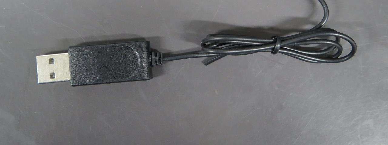
Click to zoom
Application Details
- Equipment Class
- DXX - Part 15 Low Power Communication Device Transmitter
- Date of Grant
- Aug 19, 2015
- Application Purpose
- Original Equipment
- Date of Application
- Aug 19, 2015
- Equipment Note
- Copter of Vektor Drone
- Frequency Range
- 2402.00000000 - 2475.00000000
- Country
- Hong Kong
Documents & Files
Document Text
Text extracted from the exhibit documents filed with the FCC. Open a document above to read the original.
Users Manual
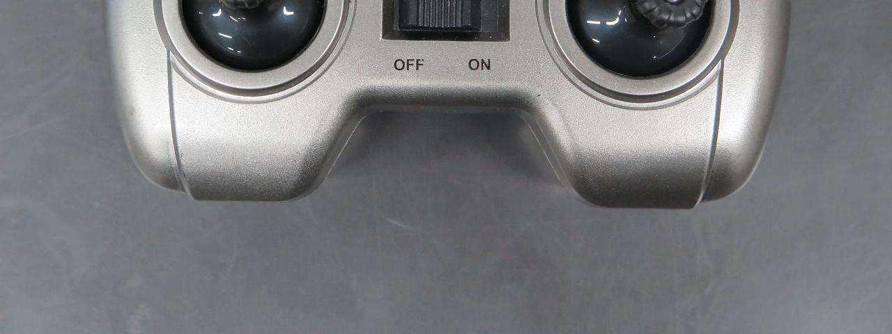
© 2015 RadioShack Corporation. All rights reserved. RadioShack is a registered trademark used by RadioShack Corporation. 04A15 6001357, 6001376 Printed in China Vektor Drone Install Batteries in the Remote Control 1. On the remote control, set the ON/OFF switch to OFF. 2. Use a screwdriver to open the battery compartment. 3. Insert two AAA batteries (not included), matching the polarities (+ and –) marked inside. Use alkaline batteries for optimal performance. Replace the cover. Note: If the remote control’s LED flashes during use, the batteries are low and should be replaced. Age 12+ Get Ready to Fly 1. Turn on the drone. The LED flashes green. 2. Place the drone on level ground. 3. Turn on the remote control. The remote control's LED flashes. 4. Move the throttle all the way up and then down to pair the remote control with the drone. The drone’s blades remain still during pairing. When paired, the LEDs on both the remote control and drone light steadily. Note: If pairing fails, turn off the drone and remote control and repeat the steps above, or change locations to avoid electrical interference. Fly Your Drone 1. After pairing, push the steering control in to switch between high speed (double beep) and low speed (single beep). 2. With the drone on the ground, move the throttle forward to ascend. To avoid ground air turbulence, fly the drone at least 1 ft. (30cm) off the ground. For advanced users: Hold the remote control with one hand, resting your thumb on the throttle. Throw the drone about 9 ft. (3m) away from you, and move the throttle forward to fly. The drone adjusts itself automatically and flies smoothly. IMPORTANT: If your drone crashes upside down, pull the throttle down and switch off the remote control first. Never touch the drone when blades are still moving. We hope you enjoy your Vektor Drone from RadioShack. Please read this user’s guide before setting up and using your drone. What’s Included • Vektor Drone • Remote Control • USB Charging Cable • Spare Blades (4) • 3.7V Drone Battery • User’s Guide Charge the Drone Your drone uses a built-in lithium polymer battery for power. 1. Use the USB charging cable to connect the battery to a USB power source (such as a laptop). The LED on the USB connector lights red during charging, and turns off when charging is complete. A full charge takes about 35 minutes. A fully charged battery provides up to 4 minutes of flight time. 2. After charging, unplug the USB charging cable. Do not attempt to overcharge the battery. Caution: Use only the included USB charging cable to charge the drone's battery. Using any other cable may damage the drone. LEDON/OFF LED Arrow side up LED Rotor Blades (4) Left/Right Slide Trim Forward/Reverse Movement Trim ThrottleSteering Forward Ascend Backward Descend Slide rightTurn rightSlide leftTurn left Push (Stunt mode) Push (High/low speed) BC ON/OFF 6001357, 6001376_UG_EN.indd 14/29/2015 2:23:36 PM Trim Your Drone Move the throttle forward and see how the drone reacts. Forward/Reverse Movement Trim: If the drone tends to move forward, press 6 ; if it tends to move backward, press 5 . Left/Right Slide Trim: If the drone tends to slide right, press 5 ; if it tends to slide left, press 6 . Note: The remote control beeps when you press a trim control but stops beeping when you reach maximum trim adjustment. Land Your Drone 1. Slowly move the throttle backward to descend. Avoid moving the throttle too quickly, as it can stop the blades instantly and cause the drone to crash. 2. When you finish flying, turn off the remote control and drone. Perform Stunts 1. Push the throttle control in so that the remote control beeps repeatedly, indicating the drone is in stunt mode. 2. Use the steering control to perform stunts: • Front flip: Move steering forward • Back flip: Move steering backward • Barrel roll: Move steering right or left 3. The drone automatically exits stunt mode after performing a stunt, or you can push in the throttle control again to exit immediately. IMPORTANT: Make sure there is enough space for the drone to perform stunts without crashing into objects or people. Calibrate the Drone If controlling the drone becomes difficult, use the following steps to calibrate the drone. 1. Select an open location without strong magnetic interference and place the drone on level ground. 2. Turn on the drone and the remote control, then pair the remote control with the drone. 3. With the throttle all the way down, move the steering control all the way up until the drone's LED flashes rapidly. 4. When the drone's LED lights steadily, your drone is calibrated and should fly smoothly. Fly Safely • When flying outdoors, keep the drone away from power lines, trees, weeds, and water. • When flying indoors, keep the drone away from walls, air conditioning, air vents, fans, breakable objects, and other obstacles. • Do not fly the drone near or at other people or animals. • Keep eyes, hands, hair, and loose clothing away from moving blades. • Adult supervision is recommended at all times. CHOKING HAZARD! Small parts. Not for children under 3 years. Specifications Power .............................................................................. Drone ......................................................................... ...........3.7V 100 mAh lithium polymer battery Remote Control ....................2 × AAA batteries Remote Control ........................4 channel, 2.4GHz Control Distance ...................................65 ft. (20m) Specifications are subject to change and improvement without notice. Actual product may vary from the images found in this document. Troubleshooting Drone does not respond • Make sure the drone and remote control are switched on and paired. When paired, the LEDs of the drone and remote control light steadily. • The drone battery may be low. Fully charge the battery. See “Charge the Drone.“ • Remote control batteries may be low. Replace the batteries. • Make sure the drone is within …
Text truncated - open the document above for the full version.
Cover Letter(s)
ZEGO ELECTRONIC CO.,LTD (July 22 2015) Equipment Authorization Division Office id Engineering and Technology Federal Communications Commission 7435 Oakland Mills Road Columbia, MD 21046 Dear Sirs: ZEGE ELECTRONIC CO., LIMITE requests acceptance of the labeling proposal described below for (6001357) bearing FCC ID: 2ACS64RX. The subject (6001357) models as shown in figure 1, authorized under FCC Part 15 Class C figure 1 ZEGO ELECTRONIC CO.,LTD It is because the surface of the device does not enough to indicate the FCC statement. For this reason, (ZEGE ELECTRONIC CO., LIMITED) proposes those statements is showing on the user manual and the device is carrying the FCC ID number only. The figure2 is showing the FCC ID location. figure 2 Sincerely, ZEGE ELECTRONIC CO., LIMITED ------------------------------- Jade Wang Vice-general Manager
External Photos
External Photo
ID Label/Location Info
Label sample
Internal Photos
Internal Photo
Test Report
TEST REPORT Report No. : AT0050896(6) Date : 05 Aug 2015 For and on behalf of CMA Industrial Development Foundation Limited Authorized Signature : Page 1 of 38 Mr. WONG Lap-pong, Andrew Manager Electrical Division FCC ID: 2ACS64RX Application No. : LT018736(3) Applicant : Zego Electronic Company Limited (Shenzhen Yangri Electronic Ltd) Room 703, Kowloon Building, 555 Nathan Road, Kowloon, HK Sample Description : One(1) item of submitted sample stated to be Copter of Vektor 5cm 4-ch Drone of Model No. 6001357, 6001391, 6001392 and 6001393 Sample registration No. : RT019576-001, RT035651-001 Radio Frequency : 2402MHz – 2475MHz Transceiver Rating : 3.7V rechargeable battery : USB 5V charging adaptor No. of submitted sample : Two (2) set (s) Date Received : 24 Apr 2015, 24 Jul 2015 Test Period : 07 May 2015 to 31 Jul 2015. Test Requested : FCC Part 15 Certificate Test Method : 47 CFR Part 15 (10-1-14 Edition) ANSI C63.4 – 2009 Test Engineer : Mr. LEUNG Shu-kan, Ken Test Result : See attached sheet(s) from page 2 to 38. Conclusion : The submitted sample was found to comply with requirement of FCC Part 15 Subpart B and C. Remark : All four models are the same in circuitry and components; and therefore model 6001357 was chosen to be the representative of the test sample. The difference between the tested model and the declared model(s) is/are the Model no. and Color TEST REPORT Report No. : AT0050896(6) Date : 05 Aug 2015 Page 2 of 38 FCC ID: 2ACS64RX Table of Contents 1 General Information ................................................................................................................................... 3 1.1 General Description ............................................................................................................................ 3 1.2 Location of the test site ....................................................................................................................... 4 1.3 List of measuring equipment............................................................................................................... 5 1.4 Measurement Uncertainty ................................................................................................................... 6 2 Description of the radiated emission test ................................................................................................... 7 2.1 Test Procedure .................................................................................................................................... 7 2.2 Test Result .......................................................................................................................................... 8 2.3 Radiated Emission Measurement Data ............................................................................................... 9 3 Description of the Line-conducted Test ................................................................................................... 14 3.1 Test Procedure .................................................................................................................................. 14 3.2 Test Result ........................................................................................................................................ 14 3.3 Graph and Table of Conducted Emission Measurement Data .......................................................... 14 4 Photograph ............................................................................................................................................... 15 4.1 Photographs of the Test Setup for Radiated Emission and Conducted Emission ............................. 15 4.2 Photographs of the External and Internal Configurations of the EUT .............................................. 15 5 Supplementary document ......................................................................................................................... 16 5.1 Bandwidth ......................................................................................................................................... 16 6 Appendices ............................................................................................................................................... 17 TEST REPORT Report No. : AT0050896(6) Date : 05 Aug 2015 Page 3 of 38 FCC ID: 2ACS64RX 1 General Information 1.1 General Description The equipment under test (EUT) is the copter for Vektor 5cm 4-ch Drone. The EUT is power by 3.7V rechargeable battery. It operates at 2402MHz – 2475MHz. When the receiver receives radio signal from transmitter, it will take corresponding actions. The brief circuit description is listed as follows: - U1, U2 and its associated circuit act as MCU - U3 and its associated circuit act as RF circuit - Y1 and its associated circuit act as oscillator - LED5 and its associated circuit act as LED - M1, M2, M3, M4 and its associated circuit act as motor - Q5 and its associated circuit act as Power regulator TEST REPORT Report No. : AT0050896(6) Date : 05 Aug 2015 Page 4 of 38 FCC ID: 2ACS64RX 1.2 Location of the test site FCC Registered Test Site Number: 552221 Radiated emissions measurements are investigated and taken pursuant to the procedures of ANSI C63.4 – 2009. A Semi-Anechoic Chamber Testing Site is set up for investigation and located at: Ground Floor, Yan Hing Centre, 9 – 13 Wong Chuk Yeung Street, Fo Tan, Shatin, New Territories, Hong Kong. Conducted emissions measurements are investigated and also taken pursuant to the procedures of ANSI C63.4 – 2009. A shielded room is located at : Ground Floor, Yan Hing Centre, 9 – 13 Wong Chuk Yeung Street, Fo Tan, Shatin, New Territories, Hong Kong. TEST REPORT Report No. : AT0050896(6) Date : 05 Aug 2015 Page 5 of 38 FCC ID: 2ACS64RX 1.3 List of measuring equipment Equipment Manufacturer Model No. Serial No. Calibration Due Date Calibration Period EMI Test Receiver R&S ESCI 100152 28 Aug 2015 1Year Spectrum Analyzer R&S FSV40 100628 02 Feb …
Text truncated - open the document above for the full version.
Test Report
TEST REPORT Report No. : AT0050896(6) Date : 05 Aug 2015 Tested by: Reviewed by: Mr. LEUNG Shu-kan, Ken Mr. WONG Lap-pong, Andrew Page 32 of 38 FCC ID: 2ACS64RX A6 Conducted Emission Measurement Date TEST REPORT Report No. : AT0050896(6) Date : 05 Aug 2015 Tested by: Reviewed by: Mr. LEUNG Shu-kan, Ken Mr. WONG Lap-pong, Andrew Page 33 of 38 FCC ID: 2ACS64RX A6 Conducted Emission Measurement Date TEST REPORT Report No. : AT0050896(6) Date : 05 Aug 2015 Tested by: Reviewed by: Mr. LEUNG Shu-kan, Ken Mr. WONG Lap-pong, Andrew Page 34 of 38 FCC ID: 2ACS64RX A6 Conducted Emission Measurement Date
Test Report
TEST REPORT Report No. : AT0050896(6) Date : 05 Aug 2015 Tested by: Reviewed by: Mr. LEUNG Shu-kan, Ken Mr. WONG Lap-pong, Andrew Page 37 of 38 FCC ID: 2ACS64RX A8. 20dB Bandwidth Plot Bandwidth 1 (2402MHz) Bandwidth 2 (2433MHz) TEST REPORT Report No. : AT0050896(6) Date : 05 Aug 2015 Tested by: Reviewed by: Mr. LEUNG Shu-kan, Ken Mr. WONG Lap-pong, Andrew Page 38 of 38 FCC ID: 2ACS64RX A8. 20dB Bandwidth Plot Bandwidth 3 (2475MHz) ***** End of Report *****
Test Report
TEST REPORT Report No. : AT0050896(6) Date : 05 Aug 2015 Tested by: Reviewed by: Mr. LEUNG Shu-kan, Ken Mr. WONG Lap-pong, Andrew Page 35 of 38 FCC ID: 2ACS64RX A7. Band Edge Lower edge (Peak measurement) Lower edge (Average measurement) TEST REPORT Report No. : AT0050896(6) Date : 05 Aug 2015 Tested by: Reviewed by: Mr. LEUNG Shu-kan, Ken Mr. WONG Lap-pong, Andrew Page 36 of 38 FCC ID: 2ACS64RX A7. Band Edge Upper edge (Peak measurement) Upper edge (Average measurement)
Test Report
Antenna Compliance According to FCC 15.203, an intentional radiator shall be designed to ensure that no antenna other than that furnished by the responsible party shall be used with the device. The use of a permanently attached antenna or of an antenna that uses a unique coupling to the intentional radiator shall be considered sufficient to comply with the provisions of this section. The following picture is the antenna of the EUT Antenna of this product is unique antenna and unchangeable; fulfill the requirement of this section Antenna
Test Setup Photos
Test Setup Photo Front view (30MHz – 1GHz) Rear view (30MHz – 1GHz) Front view (9kHz – 30MHz) Rear view (9kHz – 30MHz) Front view (1GHz – 25GHz) Rear view (1GHz – 25GHz) Front view (Charging) Rear view (Charging) Conducted emission (Front view) Conducted emission (Rear view) Conducted emission (Side view)
Contact Information
Applicant
JADE WANG(VICE-GENERAL MANAGER)
Test Firm
CMA Industrial Development Foundation LimitedJoey Kwok
[email protected]+852 2690 8255
Technical Specifications
| # | Rule Parts | Frequency Range | Power Output |
|---|---|---|---|
| 1 | 15C | 2.40 GHz - 2.48 GHz | - |
Other Applications from ZEGO ELECTRONIC COMPANY LIMITED
2ACS65TX
Aug 19, 2015Controller of Dominator Drone
Equipment Class
DXX - Part 15 Low Power Communication Device Transmitter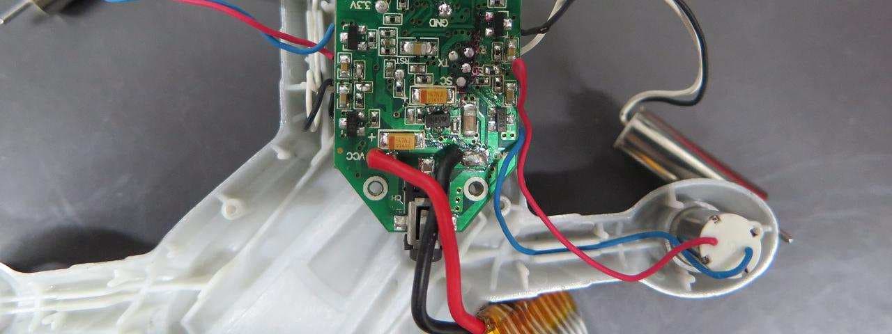
2ACS67RX
Aug 19, 2015Copter of Battle Drone
Equipment Class
DXX - Part 15 Low Power Communication Device Transmitter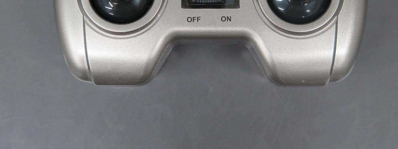
2ACS67TX
Aug 19, 2015Controlller of Battle Drone
Equipment Class
DXX - Part 15 Low Power Communication Device Transmitter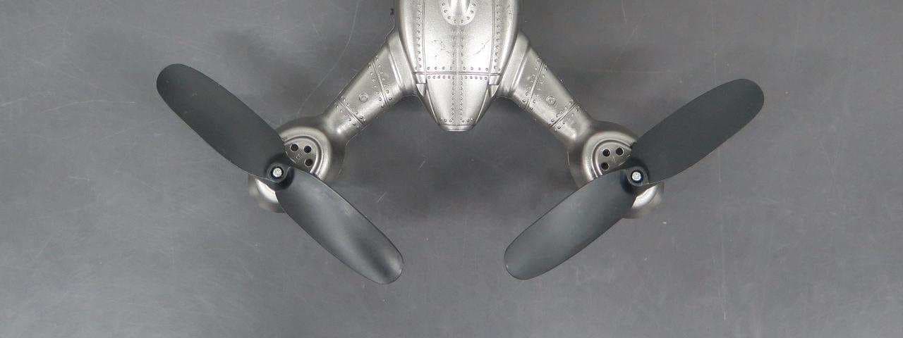
2ACS65RX
Aug 19, 2015Copter of Dominator Drone
Equipment Class
DXX - Part 15 Low Power Communication Device Transmitter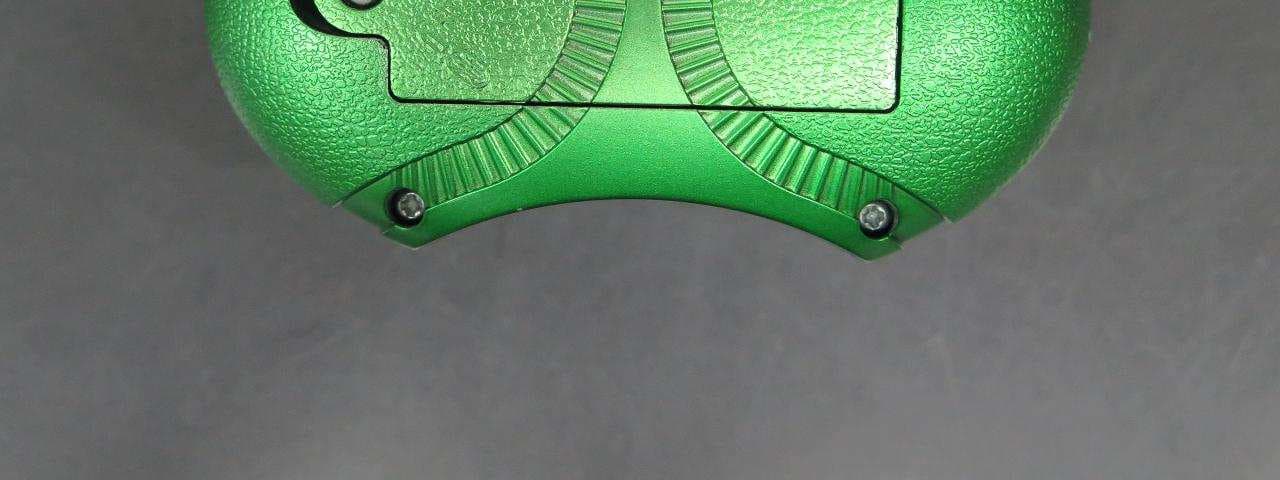
2ACS64TX
Aug 19, 2015Controller of Vektor Drone
Equipment Class
DXX - Part 15 Low Power Communication Device Transmitter