2ACVFM-920BWalkie Talkie
Shenzhen ChangTaiWei Electronic CO.,LTD
Click to zoom
Application Details
- Equipment Class
- FRF - Part 95 Family Radio Face Held Transmitter
- Date of Grant
- Apr 18, 2021
- Application Purpose
- Original Equipment
- Date of Application
- Apr 18, 2021
- Equipment Note
- Walkie Talkie
- Frequency Range
- 462.55000000 - 462.72500000
- Country
- China
Documents & Files
Document Text
Text extracted from the exhibit documents filed with the FCC. Open a document above to read the original.
Users Manual
Walkie Talkie UserGuide US 1 2 3 4 5 6 7 9 8 10 11 12 13 14 15 1 2. Backlit LCD Display 3. 4. 5. 6. Microphone 7. 8. 9.Up Button 10.Call/Lock Button 11. PTT(Pull to talk) Button . Antenna NOAA/Scan Button Down Button Menu/Power Button External Speaker/ Microphone/Charge Jack Speaker 12. Wrist Strap Connection 13. Belt Clip 14. Battery Compartment 15. Battery Door Latch Read this operating instruction carefully before using your two way radio, including the part on Product Safety and Important Notice. CAUTION Features • 22 Channels • 1 0 C h a nn e l N O AA All H a z a r ds Rad i o • Weather Alert • 121 Privacy Codes (38 CTCSS codes/83 DCS codes) • Hands-Free Operation (VOX) • Scan Channels,privacy codes • Backlit LCD Display • Call Alert Ten selectable tones • Button Lock • Speaker/Microphone/ Jack/Charge Jack • Roger Beep Selectable On/Off • Battery/Power Saver • Keystroke Tones • Battery Level Indicator • Low Battery Audible Alert • Auto Squelch • Belt Clip Product Features Maximum range may vary and is based on unobstructed line - of - sight communication under ideal conditions . Backlit LCD Display 1 2 3 4 5 6 11 12 13 10 14 8 7 9 1. Battery Level Indicator 2. VOX Icon 3. Scan Icon 4. Roger Beep Icon 5. Lock Icon 6. Low Power Icon 7. DCS/CTCSS Icons 8. Weather Icon 9. Weather Alert Icon 10. DCS/CTCSS Privacy Code Numbers 11. Power Saver Icon 12. Channel Numbers 13. Receive/Transmit Icon 14. Key Tone Icon Installing Batteries To install or replace batteries: 1. 2. 3. Remove the belt clip by pulling the tab and sliding it up. Pull the battery door lock tab up to release the battery cover. Insert 3 "AA" batteries. Put the battery cover back into place. Snap the lock tab and belt clip back into place. Product Features ChannelFrequency(MHz)ChannelFrequency(MHz) 1462.562512467.6625 2462.587513467.6875 3462.612514467.7125 4462.637515462.5500 5462.662516462.5750 6462.687517462.6000 7462.712518462.6250 8467.562519462.6500 9467.587520462.6750 10467.612521462.7000 11467.637522462.7250 1.Do not mix old and new batteries 2.Do not mix alkaline, standard (carbon-zinc) or rechargeable (nickel-cadmium) batteries. Quick Start 1. Press and hold the Menu/Power button to turn on your radio. 2. Press the Menu, Press the Up or Down button to select a channel. Both radios must be tuned to the same channel/privacy code to communicate. 3. Press and hold the PTT button while speaking into the microphone. 4. When finished talking, release the PTT button and listen for a response. Turning on Your Radio Press and hold the Menu/Power button until you hear a series of audible tones indicating the radio is on.Your radio is now in Standby mode,ready to receive transmissions. The radio is always in Standby mode except when the PTT, Call or Menu/Power buttons are pressed. Battery Low When battery power is low, the final bar in the Battery Low icon will blink and an audible tone will sound twice before the radio shuts off. Your batteries should be replaced or recharged, if using rechargeable batteries. The radio will display flashing battery icon while charging. Battery Low For charging radios (A/Batteries:Just for batteries and adpater packaging option) 1.To charge a single radio, simply insert the connector directly into the charge jack located on the bottom of the radio. The radio will display flashing battery icon while charging. Recommends your radio be turned off while being charged. dpater Auto Battery Save If there are no transmissions within 3 seconds,the radio will automatically switch to Battery Save mode and the Power Saver icon will displayed. This will not affect the radio’s ability to receive incoming transmissions. 1. Press and hold the PTT button. 2. With the microphone about two inches (2.5-5 cm) from your mouth, speak in a normal voice. 3. Release the button when you are finished talking and listen for a response. You cannot receive incoming calls while pressing the button. Both radios must be tuned to the same channel/privacy code to communicate. PTT PTT Communicating with Another Person With the radio on, select any of the 22 channels by pressing Menu and the Up or Down button. Both radios must be tuned to the same channel to communicate. To Select a Channel Release the button to receive incoming transmissions. Your radio is always in Standby mode while the or Call buttons are not pressed. PTT PTT Listening for a Response Press the Up or at the standby mode. A double beep sound is used to indicate the minimum and maximum volume levels (1 through 8). Down button To Adjust Volume Channel Number Listening Volume Level Press and release the Call button. The other person will hear a two second call tone. This tone is used only to establish voice communications.See page 8 on how to select between ten call tone settings. Call Button The Lock function locks the Up, Down, Scan and Menu/Power buttons to prevent accidental operation. To turn the lock on or off: –Press and hold the Call/Lock button for two seconds. A double beep sound is used to confirm your lock on or off request. When in Lock mode,the Lock icon will be displayed. Lock Function By scrolling through the MENU function, you will be able to select or turn on preferred features of your radio. When scrolling through the Menu function, your radio features will be displayed in the same predetermined order: Set channels Set CTCSS Privacy Codes Set DCS Privacy Codes Set Vox On/Off Set Vox Sensitivity Set Call Tones 1-10 Set Roger Beep On/Off Set Key Tones On/Off Scrolling Through the Menu Function Privacy Codes Your radio incorporates two advanced coded squelch systems that can help to reduce interference from other users on any given channel. CTCSS (Continuous Tone Coded Squelch System) provides 38 privacy codes and DCS (Digitally Coded Squelch) provides 83 privacy codes. This provides a total of 121 Privacy Codes. Either system can be used on all channels, but both systems cannot be used on the same channel at the same time. Lock Icon To successfully …
Text truncated - open the document above for the full version.
External Photos
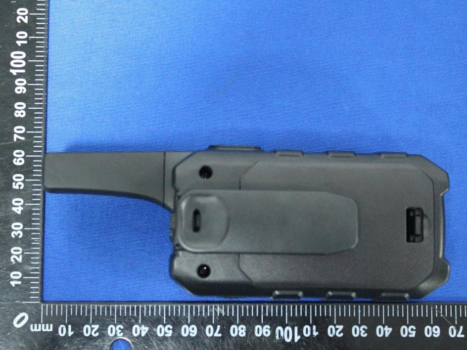
Report No.: 2102RSU071-UE 1 of 4 EUT External Photograph (1) EUT Photo (2) EUT Photo Report No.: 2102RSU071-UE 2 of 4 (3) EUT Photo (4) EUT Photo Report No.: 2102RSU071-UE 3 of 4 (5) EUT Photo (6) EUT Photo Report No.: 2102RSU071-UE 4 of 4 (7) EUT Photo
Internal Photos
Report No.: 2102RSU071-UE 1 of 2 EUT Internal Photograph (1) EUT Photo (2) EUT Photo Report No.: 2102RSU071-UE 2 of 2 (3) EUT Photo (4) EUT Photo
RF Exposure Info
MRT Technology (Suzhou) Co., Ltd Report No.: 2102RSU071-U2 Phone: +86-512-66308358 Report Version: V01 Web: www.mrt-cert.com Issue Date: 04-12-2021 1 of 48 FCC ID: 2ACVFM-920B Applicant: Shenzhen ChangTaiWei Electronic CO., LTD Application Type: Certification Product: Walkie Talkie Model No.: M-920 FCC Classification: Family Radio Service (FRS) FCC Rule Part(s): FCC 47 CFR Part 2.1093 Test Procedure(s): IEEE 1528:2013; IEEE C95.1- 2005; KDB 447498 D01v06; KDB 865664 D01v01r04 Test Date: 10/31/2019 Reviewed By: Vincent Yu Approved By: Robin Wu SAR MEASUREMENT REPORT The test results relate only to the samples tested. This equipment has been shown to be capable of compliance with the applicable technical standards as indicated in the measurement report and was tested in accordance with the measurement procedures specified in IEEE1528, KDB 447498 and KDB 865664. Test results reported herein relate only to the item(s) tested. The test report shall not be reproduced except in full without the written approval of MRT Technology (Suzhou) Co., Ltd. Report No.: 2102RSU071-U2 2 of 48 Revision History Report No. Version Description Issue Date Note 2102RSU071-U2 Rev. 01 Initial Report 04-12-2021 Valid Note: This report is based on MRT original report (Report No.: 1910RSU037-U2), FCC ID: 2ACVFM-920, to copy report. Report No.: 2102RSU071-U2 3 of 48 CONTENTS Description Page 1. General Information .................................................................................................................. 5 1.1. Applicant .......................................................................................................................... 5 1.2. Manufacturer ................................................................................................................... 5 2. Product Information ................................................................................................................. 6 2.1. General Description for EUT ........................................................................................... 6 2.2. Product Specification Subjective to this Report ............................................................... 6 2.3. Ancillary Equipment ......................................................................................................... 6 3. Summary of Test Result ........................................................................................................... 7 3.1. Test Standards ................................................................................................................ 7 3.2. Environment Condition .................................................................................................... 7 3.3. RF Exposure Limits ......................................................................................................... 7 3.4. Test Result Summary ...................................................................................................... 8 4. Specific Absorption Rate (SAR) .............................................................................................. 9 4.1. Introduction ...................................................................................................................... 9 4.2. Definition ......................................................................................................................... 9 5. DASY6 Measurement System ................................................................................................ 10 5.1. Introduction .................................................................................................................... 10 5.2. DASY6 Measurement System Diagram ........................................................................ 10 5.3. System Components Details ......................................................................................... 11 6. The SAR Measurement Procedure ........................................................................................ 22 6.1. Measurement Process Diagram .................................................................................... 22 6.2. Test Position Definition .................................................................................................. 23 6.3. Test Procedure .............................................................................................................. 26 7. System Verificaiton ................................................................................................................. 28 7.1. Tissue Check ................................................................................................................. 28 7.2. System Check ............................................................................................................... 31 8. Analysis and Results.............................................................................................................. 33 8.1. Antenna Location .......................................................................................................... 33 8.2. Conducted Power .......................................................................................................... 34 8.3. SAR Exclusion Analysis ................................................................................................ 35 8.4. Required Configurations of SAR Test ............................................................................ 36 8.5. SAR Test Results .......................................................................................................... 37 Report No.: 2102RSU071-U2 4 of 48 8.6. Estimated SAR Calculation ........................................................................................... 38 9. Simultaneous Transmission Analysis .................................................................................. 39 9.1. Simultaneous Transmission Scenario ........................................................................... 39 9…
Text truncated - open the document above for the full version.
RF Exposure Info
Return Loss and Impedance Indicated By Head Tissue Meas. Items Original Value Current Value Deviation Return Loss(dB) -22.469 -23.62 -5.12% Impedance 56.906Ω - 4.125jΩ 54.23Ω - 5.41jΩ -2.676Ω Real part -1.285Ω Imaginary part Test Date: 2019/05/13 Return Loss and Impedance Indicated By Body Tissue Meas. Items Original Value Current Value Deviation Return Loss(dB) -22.706 -25.88 -14.00% Impedance 54.908Ω - 5.926jΩ 52.28Ω - 4.73jΩ -2.628Ω Real part 1.196Ω Imaginary part Test Date: 2019/05/13
Test Report
Antenna Spec Applicant: Shenzhen Changtaiwei Electronic CO.,LTD Product Name: Walkie Talkie FCC ID: 2ACVFM-920B Summary ITEM ANT SPEC Model Name 462 ~ 467MHz ANT Antenna Typpe Fixed external Polarization Vertical Horizontal Center Frequency 462MHz 462MHz Max. Gain -12.82dBi -14.42dBi Vertical (dBi) Horizontal (dBi)
Test Report
MRT Technology (Suzhou) Co., Ltd Report No.: 2102RSU071-U1 Phone: +86-512-66308358 Report Version: V01 Web: www.mrt-cert.com Issue Date: 04-12-2021 1 of 45 FCC ID: 2ACVFM-920B Applicant: Shenzhen ChangTaiWei Electronic CO., LTD Application Type: Certification Product: Walkie Talkie Model No.: M-920 FCC Rule Part(s): FCC Part 95 Subpart B Test Procedure(s): ANSI/TIA-603-E: 2016 ANSI C63.26: 2015 Test Date: October 06 ~ November 11, 2019 Reviewed By: Vincent Yu Approved By: Robin Wu MEASUREMENT REPORT FCC PART 95 Walkie Talkie The test results relate only to the samples tested. This equipment has been shown to be capable of compliance with the applicable technical standards as indicated in the measurement report and was tested in accordance with the measurement procedures specified in ANSI/TIA-603-E:2016 and ANSI C63.26. Test results reported herein relate only to the item(s) tested. The test report shall not be reproduced except in full without the written approval of MRT Technology (Suzhou) Co., Ltd. Report No.: 2102RSU071-U1 2 of 45 Revision History Report No. Version Description Issue Date Note 2102RSU071-U1 Rev. 01 Initial Report 04-12-2021 Valid Note: This report is based on MRT original report (Report No.: 1910RSU037-U1), FCC ID: 2ACVFM-920, to copy report. Report No.: 2102RSU071-U1 3 of 45 CONTENTS Description Page 1. GENERAL INFORMATION ........................................................................................................ 5 1.1. Applicant .......................................................................................................................... 5 1.2. Manufacturer ................................................................................................................... 5 2. PRODUCT INFORMATION ........................................................................................................ 6 2.1. Equipment Description .................................................................................................... 6 2.2. Operating Frequency and Channel List ........................................................................... 6 3. ANTENNA REQUIREMENTS .................................................................................................... 7 4. TEST EQUIPMENT CALIBRATION DATE ................................................................................ 8 5. MEASUREMENT UNCERTAINTY ........................................................................................... 10 6. TEST RESULT ......................................................................................................................... 11 6.1. Summary ....................................................................................................................... 11 6.2. Frequency Accuracy ...................................................................................................... 12 6.2.1. Test Limit ................................................................................................................... 12 6.2.2. Test Procedure .......................................................................................................... 12 6.2.3. Test Setup ................................................................................................................. 13 6.2.4. Test Result ................................................................................................................. 14 6.3. Transmit Power ............................................................................................................. 16 6.3.1. Test Limit ................................................................................................................... 16 6.3.2. Test Procedure .......................................................................................................... 16 6.3.3. Test Setup ................................................................................................................. 17 6.3.4. Test Result ................................................................................................................. 18 6.4. Occupied Bandwidth ..................................................................................................... 20 6.4.1. Test Limit ................................................................................................................... 20 6.4.2. Test Procedure .......................................................................................................... 20 6.4.3. Test Setup ................................................................................................................. 20 6.4.4. Test Result ................................................................................................................. 21 6.5. Unwanted Emissions Mask ........................................................................................... 22 6.5.1. Test Limit ................................................................................................................... 22 6.5.2. Test Procedure .......................................................................................................... 22 6.5.3. Test Setup ................................................................................................................. 23 6.5.4. Test Result ................................................................................................................. 24 6.6. Modulation Characteristics ............................................................................................ 27 6.6.1. Test Limit ................................................................................................................... 27 Report No.: 2102RSU071-U1 4 of 45 6.6.2. Test Procedure .......................................................................................................... 28 6.6.3. Test Setup .......................................................................................................…
Text truncated - open the document above for the full version.
Test Setup Photos
Report No.: 2102RSU071-UT FCC Part 95B Test Setup Photos Description: Radiated Emission Test Setup for below 1GHz Description: Radiated Emission Test Setup for above 1GHz Report No.: 2102RSU071-UT SAR Test Setup Photograph Description: Head Front of Face with 25mm gap Description: Body Back with 0mm gap Report No.: 2102RSU071-UT FCC Part 15B Test Setup Photographs Test Mode: Mode 2 Description: Front View of Conducted Emission Test Setup for Power Port Test Mode: Mode 2 Description: Back View of Conducted Emission Test Setup for Power Port Report No.: 2102RSU071-UT Test Mode: Mode 1 Description: Radiated Emission Test Setup for below 1GHz Test Mode: Mode 1 Description: Radiated Emission Test Setup for above 1GHz Report No.: 2102RSU071-UT Test Mode: Mode 2 Description: Radiated Emission Test Setup for below 1GHz Test Mode: Mode 2 Description: Radiated Emission Test Setup for above 1GHz
Contact Information
Applicant
YU YONGJIE(CEO)
Test Firm
MRT Technology (Suzhou) Co., Ltd.Mr. Marlin Chen
[email protected]+86-512-66308358
Technical Specifications
| # | Rule Parts | Frequency Range | Power Output | Emission | Tolerance |
|---|---|---|---|---|---|
| 3 | 95B | 462.55 MHz - 462.725 MHz | 45.30 mW | 12K0F3E | 0.18 ppm |
Other Applications from Shenzhen ChangTaiWei Electronic CO.,LTD
2ACVFK-15
Aug 26, 2024Walkie Talkie
Equipment Class
FRF - Part 95 Family Radio Face Held Transmitter
2ACVFM-880B
Jun 29, 2021WalkieTalkie
Equipment Class
FRF - Part 95 Family Radio Face Held Transmitter2ACVFM-8B
Apr 10, 2021Walkie Talkie
Equipment Class
JBP - Part 15 Class B Computing Device Peripheral
2ACVFK-10B
Dec 02, 2020Walkie Talkie
Equipment Class
JBP - Part 15 Class B Computing Device Peripheral
2ACVFM-930
Sep 01, 2020Walkie Talkie
Equipment Class
FRF - Part 95 Family Radio Face Held Transmitter