2ACVFM-930Walkie Talkie
Shenzhen ChangTaiWei Electronic CO.,LTD
Click to zoom
Application Details
- Equipment Class
- FRF - Part 95 Family Radio Face Held Transmitter
- Date of Grant
- Sep 01, 2020
- Application Purpose
- Original Equipment
- Date of Application
- Sep 01, 2020
- Equipment Note
- Walkie Talkie
- Frequency Range
- 462.55000000 - 462.72500000
- Country
- China
Documents & Files
Document Text
Text extracted from the exhibit documents filed with the FCC. Open a document above to read the original.
Users Manual
Walkie Talkie UserGuide US M-930 1 2 3 4 5 6 7 9 8 10 11 12 13 14 15 1 2. Backlit LCD Display 3. 4. 5. 6. Microphone 7. 8. 9.Up Button 10.Call/Lock Button 11. PTT(Pull to talk) Button . Antenna NOAA/Scan Button Down Button Menu/Power Button External Speaker/ Microphone/Charge Jack Speaker 12. Wrist Strap Connection 13. Belt Clip 14. Battery Compartment 15. Battery Door Latch Read this operating instruction carefully before using your two way radio, including the part on Product Safety and Important Notice. CAUTION Features • 22 Channels • 10 Channel NOAA All Hazards Radio • Weather Alert • 121 Privacy Codes (38 CTCSS codes/83 DCS codes) • Hands-Free Operation (VOX) • Scan Channels,privacy codes • Backlit LCD Display • Call Alert Ten selectable tones • Button Lock • Speaker/Microphone/ Jack/Charge Jack • Roger Beep Selectable On/Off • Battery/Power Saver • Keystroke Tones • Battery Level Indicator • Low Battery Audible Alert • Auto Squelch • Belt Clip Product Features Maximum range may vary and is based on unobstructed line-of-sight communication under ideal conditions. Backlit LCD Display 1. Battery Level Indicator 2. VOX Icon 3. Scan Icon 4. Roger Beep Icon 5. Lock Icon 6. Low Power Icon 7. DCS/CTCSS Icons 8. Weather Icon 9. Weather Alert Icon 10. DCS/CTCSS Privacy Code Numbers 11. Power Saver Icon 12. Channel Numbers 13. Receive/Transmit Icon 14. Key Tone Icon 1 2 3 4 5 6 11 12 13 10 14 8 7 9 Installing Batteries To install or replace batteries: 1. 2. 3. Remove the belt clip by pulling the tab and sliding it up. Pull the battery door lock tab up to release the battery cover. Insert 3 "AA" batteries. Put the battery cover back into place. Snap the lock tab and belt clip back into place. Product Features ChannelFrequency(MHz)ChannelFrequency(MHz) 1462.562512467.6625 2462.587513467.6875 3462.612514467.7125 4462.637515462.5500 5462.662516462.5750 6462.687517462.6000 7462.712518462.6250 8467.562519462.6500 9467.587520462.6750 10467.612521462.7000 11467.637522462.7250 1.Do not mix old and new batteries 2.Do not mix alkaline, standard (carbon-zinc) or rechargeable (nickel-cadmium) batteries. Quick Start 1. Press and hold the Menu/Power button to turn on your radio. 2. Press the Menu, Press the Up or Down button to select a channel. Both radios must be tuned to the same channel/privacy code to communicate. 3. Press and hold the PTT button while speaking into the microphone. 4. When finished talking, release the PTT button and listen for a response. Turning on Your Radio Press and hold the Menu/Power button until you hear a series of audible tones indicating the radio is on.Your radio is now in Standby mode,ready to receive transmissions. The radio is always in Standby mode except when the PTT, Call or Menu/Power buttons are pressed. Battery Low When battery power is low, the final bar in the Battery Low icon will blink and an audible tone will sound twice before the radio shuts off. Your batteries should be replaced or recharged, if using rechargeable batteries. The radio will display flashing battery icon while charging. Battery Low For charging radios (A/Batteries:Just for batteries and adpater packaging option) 1.To charge a single radio, simply insert the connector directly into the charge jack located on the bottom of the radio. The radio will display flashing battery icon while charging. Recommends your radio be turned off while being charged. dpater Auto Battery Save If there are no transmissions within 3 seconds,the radio will automatically switch to Battery Save mode and the Power Saver icon will displayed. This will not affect the radio’s ability to receive incoming transmissions. 1. Press and hold the PTT button. 2. With the microphone about two inches (2.5-5 cm) from your mouth, speak in a normal voice. 3. Release the button when you are finished talking and listen for a response. You cannot receive incoming calls while pressing the button. Both radios must be tuned to the same channel/privacy code to communicate. PTT PTT Communicating with Another Person With the radio on, select any of the 22 channels by pressing Menu and the Up or Down button. Both radios must be tuned to the same channel to communicate. To Select a Channel Release the button to receive incoming transmissions. Your radio is always in Standby mode while the or Call buttons are not pressed. PTT PTT Listening for a Response Press the Up or at the standby mode. A double beep sound is used to indicate the minimum and maximum volume levels (1 through 8). Down button To Adjust Volume Channel Number Listening Volume Level Press and release the Call button. The other person will hear a two second call tone. This tone is used only to establish voice communications.See page 8 on how to select between ten call tone settings. Call Button The Lock function locks the Up, Down, Scan and Menu/Power buttons to prevent accidental operation. To turn the lock on or off: –Press and hold the Call/Lock button for two seconds. A double beep sound is used to confirm your lock on or off request. When in Lock mode,the Lock icon will be displayed. Lock Function By scrolling through the MENU function, you will be able to select or turn on preferred features of your radio. When scrolling through the Menu function, your radio features will be displayed in the same predetermined order: Set channels Set CTCSS Privacy Codes Set DCS Privacy Codes Set Vox On/Off Set Vox Sensitivity Set Call Tones 1-10 Set Roger Beep On/Off Set Key Tones On/Off Scrolling Through the Menu Function Privacy Codes Your radio incorporates two advanced coded squelch systems that can help to reduce interference from other users on any given channel. CTCSS (Continuous Tone Coded Squelch System) provides 38 privacy codes and DCS (Digitally Coded Squelch) provides 83 privacy codes. This provides a total of 121 Privacy Codes. Either system can be used on all channels, but both systems cannot be used on the same channel at the same time. Lock Icon To successfully communicate us…
Text truncated - open the document above for the full version.
External Photos
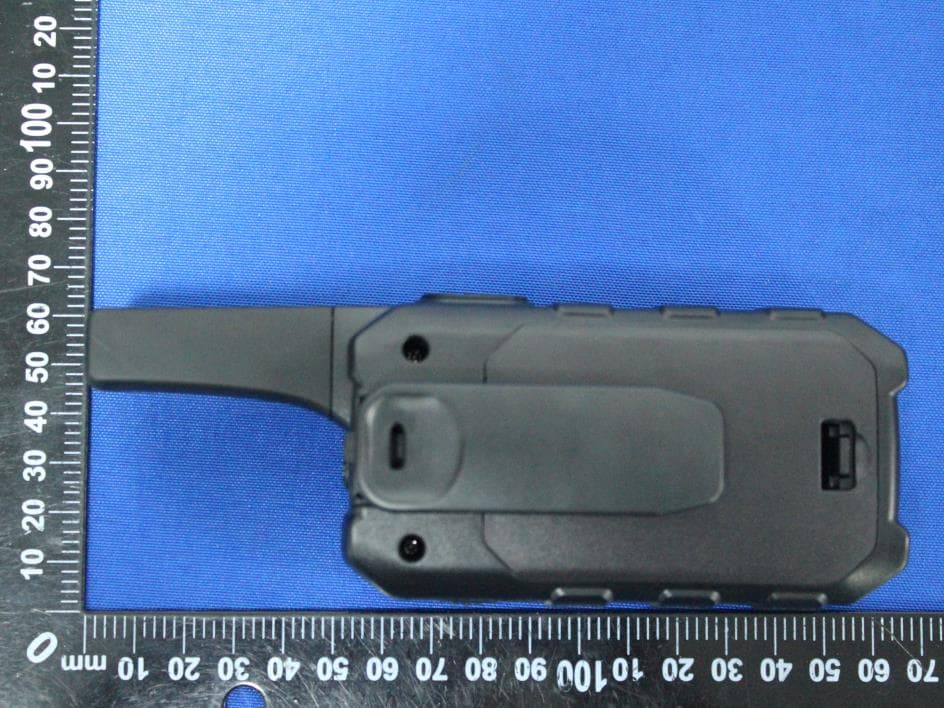
Report No.: 2007RSU062-UE 1 of 3 EUT External Photograph (1) EUT Photo (2) EUT Photo Report No.: 2007RSU062-UE 2 of 3 (3) EUT Photo (4) EUT Photo Report No.: 2007RSU062-UE 3 of 3 (5) EUT Photo (6) EUT Photo
Internal Photos
Report No.: 2007RSU062-UE 1 of 4 EUT Internal Photograph (1) EUT Photo (2) EUT Photo Report No.: 2007RSU062-UE 2 of 4 (3) EUT Photo (4) EUT Photo Report No.: 2007RSU062-UE 3 of 4 (5) EUT Photo (6) EUT Photo Report No.: 2007RSU062-UE 4 of 4 (7) EUT Photo
RF Exposure Info
Ref : ACR.345.3.20.SATU.A SHENZHEN STS TEST SERVICES CO., LTD. 1/F, BUILDING 2, ZHUOKE SCIENCE PARK, CHONGQING ROAD FUYONG, BAO’ AN DISTRICT, SHENZHEN,CHINA MVG COMOSAR DOSIMETRIC E-FIELD PROBE SERIAL NO.: SN 41/18 EPGO334 Calibrated at MVG US 2105 Barrett Park Dr. - Kennesaw, GA 30144 Calibration Date: 06/03/2020 Summary: This document presents the method and results from an accredited COMOSAR Dosimetric E-Field Probe calibration performed in MVG USA using the CALISAR / CALIBAIR test bench, for use with a COMOSAR system only. All calibration results are traceable to national metrology institutions. COMOSAR E-Field Probe Calibration Report COMOSAR E-FIELD PROBE CALIBRATION REPORT Ref: ACR.345.3.20.SATU.A Page: 2/10 This document shall not be reproduced, except in full or in part, without the written approval of MVG. The information contained herein is to be used only for the purpose for which it is submitted and is not to be released in whole or part without written approval of MVG. Name Function Date Signature Prepared by : Jérôme LUC Product Manager 6/05/2020 Checked by : Jérôme LUC Product Manager 6/05/2020 Approved by : Kim RUTKOWSKI Quality Manager 6/05/2020 Customer Name Distribution : Shenzhen STS Test Services Co., Ltd. Issue Date Modifications A 6/05/2020 Initial release COMOSAR E-FIELD PROBE CALIBRATION REPORT Ref: ACR.345.3.20.SATU.A Page: 3/10 This document shall not be reproduced, except in full or in part, without the written approval of MVG. The information contained herein is to be used only for the purpose for which it is submitted and is not to be released in whole or part without written approval of MVG. TABLE OF CONTENTS 1 Device Under Test ..................................................................................................... 4 2 Product Description ................................................................................................... 4 2.1 General Information _______________________________________________________ 4 3 Measurement Method ................................................................................................ 4 3.1 Linearity ________________________________________________________________ 4 3.2 Sensitivity _______________________________________________________________ 5 3.3 Lower Detection Limit _____________________________________________________ 5 3.4 Isotropy _________________________________________________________________ 5 3.5 Boundary Effect __________________________________________________________ 5 4 Measurement Uncertainty .......................................................................................... 5 5 Calibration Measurement Results .............................................................................. 6 5.1 Sensitivity in air __________________________________________________________ 6 5.2 Linearity ________________________________________________________________ 7 5.3 Sensitivity in liquid ________________________________________________________ 7 5.4 Isotropy _________________________________________________________________ 8 6 List of Equipment .................................................................................................... 10 COMOSAR E-FIELD PROBE CALIBRATION REPORT Ref: ACR.345.3.20.SATU.A Page: 4/10 This document shall not be reproduced, except in full or in part, without the written approval of MVG. The information contained herein is to be used only for the purpose for which it is submitted and is not to be released in whole or part without written approval of MVG. 1 DEVICE UNDER TEST Device Under Test Device Type COMOSAR DOSIMETRIC E FIELD PROBE Manufacturer MVG Model SSE2 Serial Number SN 41/18 EPGO334 Product Condition (new / used) New Frequency Range of Probe 0.45 GHz-6GHz Resistance of Three Dipoles at Connector Dipole 1: R1=0.191 M Dipole 2: R2=0.216 M Dipole 3: R3=0.197 M A yearly calibration interval is recommended. 2 PRODUCT DESCRIPTION 2.1 GENERAL INFORMATION MVG’s COMOSAR E field Probes are built in accordance to the IEEE 1528 and CEI/IEC 62209 standards. Figure 1 – MVG COMOSAR Dosimetric E field Dipole Probe Length 330 mm Length of Individual Dipoles 2 mm Maximum external diameter 8 mm Probe Tip External Diameter 2.5 mm Distance between dipoles / probe extremity 1 mm 3 MEASUREMENT METHOD The IEEE 1528 and CEI/IEC 62209 standards provide recommended practices for the probe calibrations, including the performance characteristics of interest and methods by which to assess their affect. All calibrations / measurements performed meet the fore mentioned standards. 3.1 LINEARITY The evaluation of the linearity was done in free space using the waveguide, performing a power sweep to cover the SAR range 0.01W/kg to 100W/kg. COMOSAR E-FIELD PROBE CALIBRATION REPORT Ref: ACR.345.3.20.SATU.A Page: 5/10 This document shall not be reproduced, except in full or in part, without the written approval of MVG. The information contained herein is to be used only for the purpose for which it is submitted and is not to be released in whole or part without written approval of MVG. 3.2 SENSITIVITY The sensitivity factors of the three dipoles were determined using a two step calibration method (air and tissue simulating liquid) using waveguides as outlined in the standards. 3.3 LOWER DETECTION LIMIT The lower detection limit was assessed using the same measurement set up as used for the linearity measurement. The required lower detection limit is 10 mW/kg. 3.4 ISOTROPY The axial isotropy was evaluated by exposing the probe to a reference wave from a standard dipole with the dipole mounted under the flat phantom in the test configuration suggested for system validations and checks. The probe was rotated along its main axis from 0 - 360 degrees in 15 degree steps. The hemispherical isotropy is determined by inserting the probe in a thin plastic box filled with tissue-equivalent liquid, with the plastic box illuminated with the fields from a half wave dipole. The dip…
Text truncated - open the document above for the full version.
RF Exposure Info
Any reproduction of this document must be done in full. No single part of this document may be reproduced without permission from STS, All Test Data Presented in this report is only applicable to presented Test sample. ShenZhen STS Test Services Co.,Ltd. A 1/F, Building B, Zhuoke Science Park, No.190 Chongqing Road, HepingShequ, Fuyong Sub-District, Bao’an District, Shenzhen, Guang Dong, China TEL: +86-755 3688 6288 FAX: +86-755 3688 6277 E-mail:[email protected] FCC SAR TEST REPORT Report No.: STS2008243H01 Issued for Shenzhen ChangTaiWei Electronic CO., LTD 5/F.,6 Block, XinGu Industrial Zone, GuShu Village, XiXiang Town, BaoAn District, Shenzhen City, China Product Name: Walkie Talkie Brand Name: N/A Model Name: M-930 Series Model: N/A FCC ID: 2ACVFM-930 Test Standard: ANSI/IEEE Std. C95.1 FCC 47 CFR Part 2 ( 2.1093) IEEE 1528: 2013 IEEE C95.1- 2005 KDB 447498 KDB 865664 Max. Report SAR (1g): Face up : 0.195 W/kg Back Touch : 0.863 W/kg S T L A B S Page 2 of 32 Report No.: STS2008243H01 Test Report Certification Applicant’s name ................. : Shenzhen ChangTaiWei Electronic CO., LTD Address ................................. : 5/F.,6 Block, XinGu Industrial Zone, GuShu Village, XiXiang Town, BaoAn District, Shenzhen City, China Manufacture's Name ............ : Shenzhen ChangTaiWei Electronic CO., LTD Address ................................. : 5/F.,6 Block, XinGu Industrial Zone, GuShu Village, XiXiang Town, BaoAn District, Shenzhen City, China Product Description Product Name ........................ : Walkie Talkie Brand Name ........................... : N/A Model Name ......................... : M-930 Series Model .......................... : N/A Standards ............................. : RSS 102 Issue 5,March 2015, IEC 62209-2:2010 IEEE 1528:2013, IEEE C95.1- 2005 KDB 447498, KDB 865664 The device was tested by Shenzhen STS Test Services Co., Ltd. in accordance with the measurement methods and procedures specified in KDB 865664 The test results in this report apply only to the tested sample of the stated device/equipment. Other similar device/equipment will not necessarily produce the same results due to production tolerance and measurement uncertainties. Date of Test ........................................... : Date (s) of performance of tests ............. : 19 Aug. 2020 Date of Issue .......................................... : 20 Aug. 2020 Test Result .............................................. : Pass Testing Engineer : ( Aaron Bu) Technical Manager : (Jason Lu) Authorized Signatory : (Vita Li) Page 3 of 32 Report No.: STS2008243H01 Table of Contents 1. General Information 4 1.1 EUT Description 4 1.2 Test Environment 5 1.3 Test Factory 5 2. Test Standards and Limits 6 3. SAR Measurement System 7 3.1 Definition of Specific Absorption Rate (SAR) 7 3.2 SAR System 7 4. Tissue Simulating Liquids 10 4.1 Simulating Liquids Parameter Check 10 5. SAR System Validation 12 5.1 Validation System 12 5.2 Validation Result 12 6. SAR Evaluation Procedures 13 7. EUT Test Position 14 8. Uncertainty 15 8.1 Measurement Uncertainty 15 8.2 System validation Uncertainty 16 9. Conducted Power Measurement 17 Test Result 17 10. EUT And Test Setup Photo 18 10.1 Setup Photo 18 11. SAR Result Summary 20 12. Equipment List 23 Appendix A. System Validation Plots 24 Appendix B. SAR Test Plots 26 Appendix C. Probe Calibration and Dipole Calibration Report 32 Page 4 of 32 Report No.: STS2008243H01 1. General Information 1.1 EUT Description Equipment Walkie Talkie Brand Name N/A Model name M-930 Series Model N/A Model Difference N/A Device Category Portable Product stage Production unit RF Exposure Environment Population/Uncontrolled Hardware Version N/A Software Version N/A Power Rating DC 4.5V from AA*3 battery Frequency Range GMRS 462.5625MHz-462.7125MHz(1~7 channel) 467.5625MHz-467.7125MHz (8~14 channel) 462.5500MHz-462.7250MHz(15~22 channel) Channel Spacing 25KHz Max. Reported SAR(1g): with 50% duty cycle Test Channel Face up (W/kg) Back Touch (W/kg) CH 1 0.194 0.863 CH 8 0.171 0.584 CH 15 0.195 0.854 Modulation Type: GMRS FM Antenna Specification: Spring antenna / Internal Note: 1. The EUT battery must be fully charged and checked periodically during the test to ascertain uniform power Page 5 of 32 Report No.: STS2008243H01 1.2 Test Environment Ambient conditions in the SAR laboratory: Items Required Temperature (°C) 18-25 Humidity (%RH) 30-70 1.3 Test Factory ShenZhen STS Test Services Co.,Ltd. A 1/F, Building B, Zhuoke Science Park, No.190 Chongqing Road, HepingShequ, Fuyong Sub-District, Bao’an District, Shenzhen, Guang Dong, China FCC Registration No.: 625569 A2LA Certificate No.: 4338.01 IC Registration No.: 12108A Page 6 of 32 Report No.: STS2008243H01 2. Test Standards and Limits No. Identity Document Title 1 47 CFR Part 2 Frequency Allocations and Radio Treaty Matters; General Rules and Regulations 2 ANSI/IEEE Std. C95.1-1992 IEEE Standard for Safety Levels with Respect to Human Exposure to Radio Frequency Electromagnetic Fields, 3 kHz to 300 GHz 3 IEEE Std. 1528-2013 Recommended Practice for Determining the Peak Spatial-Average Specific Absorption Rate (SAR) in the Human Head from Wireless Communications Devices: Measurement Techniques 4 FCC KDB 447498 D01 v06 Mobile and Portable Device RF Exposure Procedures and Equipment Authorization Policies 5 FCC KDB 865664 D01 v01r04 SAR Measurement 100 MHz to 6 GHz 6 FCC KDB 865664 D02 v01r02 RF Exposure Reporting 7 FCC KDB 643646 D001 SAR Test Reduction Considerations for Occupational PTT Radios (A). Limits for Occupational/Controlled Exposure (W/kg) Whole-Body Partial-Body Hands, Wrists, Feet and Ankles 0.4 8.0 20.0 (B). Limits for General Population/Uncontrolled Exposure (W/kg) Whole-Body Partial-Body Hands, Wrists, Feet and Ankles 0.08 1.6 4.0 NOTE: Whole-Body SAR is averaged over the entire body, partial-body SAR is averaged over any 1 gram of tissue defined as a tissue volume in the shape of a cube. SAR for hands, wrists, feet and ankles is av…
Text truncated - open the document above for the full version.
Test Report
MRT Technology (Suzhou) Co., Ltd Report No.: 2007RSU062-U1 Phone: +86-512-66308358 Report Version: V01 Web: www.mrt-cert.com Issue Date: 08-27-2020 1 of 43 FCC ID: 2ACVFM-930 Applicant: Shenzhen ChangTaiWei Electronic CO., LTD Application Type: Certification Product: Walkie Talkie Model No.: M-930 FCC Rule Part(s): FCC Part 95 Subpart B Test Procedure(s): ANSI/TIA-603-E: 2016 ANSI C63.26: 2015 Test Date: August 05 ~ 21, 2020 MEASUREMENT REPORT FCC PART 95 Walkie Talkie Reviewed By: ( Sunny Sun ) Approved By: ( Robin Wu ) The test results relate only to the samples tested. This equipment has been shown to be capable of compliance with the applicable technical standards as indicated in the measurement report and was tested in accordance with the measurement procedures specified in ANSI/TIA-603-E:2016 and ANSI C63.26. Test results reported herein relate only to the item(s) tested. The test report shall not be reproduced except in full without the written approval of MRT Technology (Suzhou) Co., Ltd. Report No.: 2007RSU062-U1 2 of 43 Revision History Report No. Version Description Issue Date Note 2007RSU062-U1 Rev. 01 Initial Report 08-27-2020 Valid Report No.: 2007RSU062-U1 3 of 43 CONTENTS Description Page General Information .......................................................................................................................... 5 1. INTRODUCTION ........................................................................................................................ 6 1.1. Scope .............................................................................................................................. 6 1.2. MRT Test Location ........................................................................................................... 6 2. PRODUCT INFORMATION ........................................................................................................ 7 2.1. Equipment Description .................................................................................................... 7 2.2. Operating Frequency and Channel List ........................................................................... 7 2.3. Test Methodology ............................................................................................................ 8 2.4. Labeling Requirements ................................................................................................... 8 3. ANTENNA REQUIREMENTS .................................................................................................... 9 4. TEST EQUIPMENT CALIBRATION DATE .............................................................................. 10 5. MEASUREMENT UNCERTAINTY ........................................................................................... 12 6. TEST RESULT ......................................................................................................................... 13 6.1. Summary ....................................................................................................................... 13 6.2. Frequency Accuracy ...................................................................................................... 14 6.2.1. Test Limit ................................................................................................................... 14 6.2.2. Test Procedure .......................................................................................................... 14 6.2.3. Test Setup ................................................................................................................. 14 6.2.4. Test Result ................................................................................................................. 15 6.3. Transmit Power ............................................................................................................. 17 6.3.1. Test Limit ................................................................................................................... 17 6.3.2. Test Procedure .......................................................................................................... 17 6.3.3. Test Setup ................................................................................................................. 18 6.3.4. Test Result ................................................................................................................. 19 6.4. Occupied Bandwidth ..................................................................................................... 21 6.4.1. Test Limit ................................................................................................................... 21 6.4.2. Test Procedure .......................................................................................................... 21 6.4.3. Test Setup ................................................................................................................. 21 6.4.4. Test Result ................................................................................................................. 22 6.5. Emissions Mask ............................................................................................................ 23 6.5.1. Test Limit ................................................................................................................... 23 6.5.2. Test Procedure .......................................................................................................... 23 6.5.3. Test Setup ................................................................................................................. 24 Report No.: 2007RSU062-U1 4 of 43 6.5.4. Test Result ................................................................................................................. 25 6.6. Modulation Characteristics ............................................................................................ 26 6.6.1. Test Limit .......................................................................…
Text truncated - open the document above for the full version.
Test Setup Photos
Report No.: 2007RSU062-UT Test Setup Photos Description: Radiated Emission Test Setup for below 1GHz Description: Radiated Emission Test Setup for above 1GHz
Test Setup Photos
M-930_SAR Setup photo Face up (separation distance is 25mm) Back Touch (separation distance is 0mm)
Contact Information
Applicant
YU YONGJIE(CEO)
Test Firm
MRT Technology (Suzhou) Co., Ltd.Mr. Marlin Chen
[email protected]+86-512-66308358
Technical Specifications
| # | Rule Parts | Frequency Range | Power Output | Emission | Tolerance |
|---|---|---|---|---|---|
| 3 | 95B | 462.55 MHz - 462.725 MHz | 474.20 mW | 14K0F3E | 0.78 ppm |
Other Applications from Shenzhen ChangTaiWei Electronic CO.,LTD
2ACVFK-15
Aug 26, 2024Walkie Talkie
Equipment Class
FRF - Part 95 Family Radio Face Held Transmitter
2ACVFM-880B
Jun 29, 2021WalkieTalkie
Equipment Class
FRF - Part 95 Family Radio Face Held Transmitter
2ACVFM-920B
Apr 18, 2021Walkie Talkie
Equipment Class
FRF - Part 95 Family Radio Face Held Transmitter2ACVFM-8B
Apr 10, 2021Walkie Talkie
Equipment Class
JBP - Part 15 Class B Computing Device Peripheral
2ACVFK-10B
Dec 02, 2020Walkie Talkie
Equipment Class
JBP - Part 15 Class B Computing Device Peripheral