2ADAO-KHWPO200F001Portal Beam
Kontakt Micro-Location Sp. z o.o.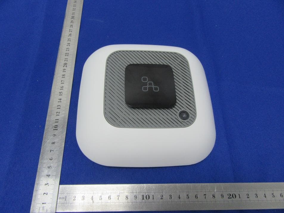
Click to zoom
Application Details
- Equipment Class
- DTS - Digital Transmission System
- Date of Grant
- May 17, 2021
- Application Purpose
- Original Equipment
- Date of Application
- May 17, 2021
- Equipment Note
- Portal Beam
- Frequency Range
- 2402.00000000 - 2480.00000000
- Country
- Poland
Documents & Files
Document Text
Text extracted from the exhibit documents filed with the FCC. Open a document above to read the original.
Users Manual
PORTAL BEAM User Manual Introduction The Portal Beam is a wireless, BLE, cloud-based, sensor platform quantifying rooms and delivering building insights in real-time. The Portal Beam uses nine different sensors: a thermal camera for occupancy and people counting, temperature, humidity, air quality, light, smoke detection, infrared beaconing, RSSI fingerprinting, and iBeacon. The Portal Beam comes with an 8-core CPU with neural network architecture and Bluetooth 5.0 readiness. Out of the box, it is compatible and seamlessly talks to any BLE-gateway. Using the 1-click, self-onboarding workflows of the Kio Cloud you can get started with it in minutes. Features ● Configurable by mobile application ● RGB LEDs signaling device state. ● Beacon broadcasting ● IR beaconing for room level tracing ● Environmental sensing (humidity, temperature, atmospheric pressure, air quality) ● Occupancy sensing with high-reliability IR camera ● Visual/sound alerts ● Specification ● Placeholder Specifications Physical Specification ● Dimensions 180x180x46 ● Dedicated mounting plate ● T-Bar mouting plate accesory Electronics ● nRF52832 ● IR Beam (4-directional LEDs) ● Environmental sensors humidity, pressure, temperature, air quality, light sensor ● Buzzer ● Light sensor ● Far Infrared Wide Angle therma camera ● Placeholder Connectivity ● Bluetooth Low Energy 5.0 ● Range up to 50 meters Power ● DC 6V-24V barrel type terminal ● 6x ER14505 (2.6 mAh) Sensors ● Temperature: Operating range: -40 to 85 c Typical accuracy: +- 1c Units: C (celsius) ● Relative Humidity: Operating range: -40 to +85°C Typical accuracy: +/- 1°C ● Air Quality Index: Range: 0 - 255 Value calculated based on multiple sensor readings ● Pressure: Operating range: 300-1100 hPa Typical accuracy: 0.6 hPa ● CO Sensor: Operating range: 1-1000 ppm ● Light Sensor: Operating range: 1-100% ● Power DC 5V-24V two-wire screw terminal 6x ER14505 (2.6 mAh) ● Environmental Requirements -40C / + 85C (-40F / +185F) 10%~90% - non condensing Additional features: ● Reset button ● RGB Led Device status information & alerting Installation This section guides you on how to correctly mount Portal Beam. There are two scenarios covered—how to mount Portal Beam for room occupancy and desk occupancy due to Portal Beam wide angle thermal camera nature. There are differences in coverage for both of these scenarios. What's in the box Portal Beam is shipped with 3M double-sided tape as the easiest way to mount the device, a set of batteries and a mounting kit to screw the device onto the ceiling. Also there is an additional mounting bracket available for suspended ceiling sold separately. Features On the side of the device you can find: • Reset button - allows you to reset the device • Power switch - to power on/off the device when its running on batteries • DC socket • LEDs that indicate state of the device All of the above are covered by device casing, and are not visible for users. Placement Before you begin with Portal Beam mounting on the ceiling, remember to scan the QR code on the back of the device using the Kio Installer App. Occupancy monitoring For occupancy features it is crucial to calculate the coverage correctly and mount Portal Beam in the correct part of the ceiling depending on what area you need to monitor. Portal Beam is equipped with a Far Infrared Wide Angle therma camera so the coverage depends on how high it is mounted. The lowest point you can mount Portal Beam is 2,4m and the highest is 4,0m to achieve best accuracy. Pictures taken by the thermal camera are passed to ML based algorithms that can recognize people-based heat detection on a picture. Note Portal Beam checks occupancy once a minute and provides full privacy. No pictures are saved on the device, the only information sent to the cloud is the number of people detected. Room You can use Portal Beam to monitor room occupancy. You can place a Portal Beam on the ceiling in the middle of the square that you need to monitor. Please note, as for now only one Portal Beam per room is supported. Coverage table As Portal Beam needs to be able to see the thermal image of the body, please refer to the below table on what coverage is available for room occupancy scenario (standing people). Mounting Height Coverage Square size 2,4m 2,27㎡ 1,51m x 1,51m 2,6m 3,99㎡ 2,00m x 2,00m 2,8m 6,19㎡ 2,59m x 2,59m 3,0m 8,86㎡ 2,98m x 2,98m 3,2m 12,02㎡ 3,47m x 3,47m 3,4m 15,66㎡ 3,96m x 3,96m 3,6m 19,78㎡ 4,45m x 4,45m 3,8m 24,37㎡ 4,94m x 4,94m 4,0m 29,45㎡ 5,43m x 5,43m Desk Portal Beam can also be used to monitor desk occupancy, or just sitting people. Coverage table Please see reference calculations for desk occupancy, since the distance from Portal Beam to the body of sitting people is greater than for the room occupancy scenario, coverage is slightly increased. Mounting Height Coverage Square size 2,4m 7,47㎡ 2,73m x 2,73m 2,6m 10,38㎡ 3,22m x 3,22m 2,8m 13,78㎡ 3,71m x 3,71m 3,0m 17,66㎡ 4,20m x 4,20m 3,2m 22,01㎡ 4,69m x 4,69m 3,4m 26,82㎡ 5,18m x 5,18m 3,6m 19,78㎡ 4,45m x 4,45m 3,8m 24,37㎡ 4,94m x 4,94m 4,0m 29,45㎡ 5,43m x 5,43m Info Please note, all calculations are based on average people height of 185cm. Mounting options Tape Mount • Step 1: Peel one side of mounting tape and stick it to the back of Portal Beam • Step 2: Peel other side of mounting tape and stick it to the ceiling • Step 3: Ready Ceiling-mount Standard mount needs to be screwed to the ceiling. • Step 1: Put wall plugs in drilled holes. • Step 2: Put the mounting kit against the ceiling and screw it in. • Step 3: Put Portal Beam to the mounting kit and rotate it gently to lock it. T-rail mount T-rail mount allows you to mount Portal Beam easily to a suspended ceiling. • Step 1: Put all elements together • Step 2: Lock trail to the suspended ceiling bar • Step 3: Screw standard mount to t-rail mount • Step 4: Put Portal Beam to the standard mount • Step 5: Rotate it gently to lock it. Configuration This section explains how to configure your Portal Beams. M…
Text truncated - open the document above for the full version.
Cover Letter(s)
Kontakt Micro-Location Sp. z o.o. 2021.05.11 Eurofins Electrical and Electronic Testing NA, Inc. 914 W. Patapsco Avenue Baltimore, MD 21230 USA RE: CONFIDENTIALITY REQUEST FOR EUT NAME: Portal Beam Trademark: Kontakt.io MODEL : KHWPO200F001 FCC ID: 2ADAO-KHWPO200F001 To Whom It May Concern: This letter serves as an official request for confidentiality under sections 0.457 and 0.459 of CFR 47. We have requested that the - Block Diagram - Schematics - Operational Description required to be submitted with this application be permanently withheld from public review. The above materials contain trade secrets and proprietary information not customarily released to the public. The public disclosure of these materials may be harmful to the applicant and provide unjustified benefits to its competitors. Please contact me if there is any information you may need. Sincerely, Client’s signature: Client’s name / title : Joanna Wolczanska /Ms Contact information / address: ul. Stoczniowcow 3, Krakow, Poland, 30-709
Cover Letter(s)
Kontakt Micro-Location Sp. z o.o. 2021.05.11 Eurofins Electrical and Electronic Testing NA, Inc. 914 W. Patapsco Avenue Baltimore, MD 21230 USA RE: LETTER OF AGENT AUTHORIZATION To Whom It May Concern: We, the undersigned, hereby authorize Shenzhen BCTC Testing Co., Ltd to act on our behalf in all matters relating to application for equipment authorization, including the signing of all documents relating to these matters. We also hereby certify that no party to the application authorized hereunder is subject to the denial of benefits, including FCC benefits, pursuant to Section 5301 of the Anti-Drug Abuse Act of 1988, 21 U.S.C.853(a). This agreement expires one year from the current date. Sincerely, Client’s signature: Client’s name / title : Joanna Wolczanska /Ms Contact information / address: ul. Stoczniowcow 3, Krakow, Poland, 30-709
External Photos
External Photos
ID Label/Location Info
Size:40*20mm Label Location FCC ID: 2ADAO-KHWPO200F001 This device complies with Part 15 of the FCC Rules. Operation is subject to the following two conditions:(1)This device may not cause harmful interfer ence, and (2) this device must accept any interference received, including interference that may cause undesired operation.
Internal Photos
Internal Photos Antenna
RF Exposure Info
FCC §15.247 (i), §2.1091 – RF Exposure FCC ID: 2ADAO-KHWPO200F001 Applied procedures / limit According to FCC §15.247(i) and §1.1307(b)(1), systems operating under the provisions of this section shall be operated in a manner that ensures that the public is not exposed to radio frequency energy level in excess of the Commission’s guidelines. Limits for Occupational / Controlled Exposure Frequency Range (MHz) Electric Field Strength (E) (V/m) Magnetic Field Strength (H) (A/m) Power Density (S) (mW/ cm 2 ) Averaging Time |E| 2 ,|H| 2 or S (minutes) 0.3-3.0 614 1.63 (100)* 6 3.0-30 1842 / f 4.89 / f (900 / f)* 6 30-300 61.4 0.163 1.0 6 300-1500 F/300 6 1500-100,000 5 6 Note: ƒ is frequency in MHz * = Power density limit is applicable at frequencies greater than 100 MHz Limits for General Population / Uncontrolled Exposure Frequency Range (MHz) Electric Field Strength (E) (V/m) Magnetic Field Strength (H) (A/m) Power Density (S) (mW/ cm 2 ) Averaging Time |E| 2 ,|H| 2 or S (minutes) 0.3-1.34 614 1.63 (100)* 30 1.34-30 824/f 2.19/f (180/f)* 30 30-300 27.5 0.073 0.2 30 300-1500 F/1500 30 1500-100,000 1.0 30 Note: f = frequency in MHz * = Plane-wave equivalent power density MPE PREDICTION Predication of MPE limit at a given distance, Equation from OET Bulletin 65, Edition 97-01 Where: S = power density P = power input to antenna G = power gain of the antenna in the direction of interest relative to an isotropic radiator R = distance to the center of radiation of the antenna, R=0.2m TEST RESULTS Tune up Produce power Maximu m peak output power (dBm) Output power to antenna (mW) Antenna Gain (numeric) Power Density (S) (mW/ cm2) Limit (mW/ cm2) Result GFSK 2±1 3 2.0 1.35 (1.3dBi) 0.0005 1 Pass
Test Report
No.:BCTC/RF-EMC-005 Page: 1 of 50 Edition:A.3 TEST REPORT Shenzhen BCTC Testing Co., Ltd. Report No.: BCTC2104188064E Applicant: Kontakt Micro-Location Sp. z o.o. Product Name: Portal Beam Model/Type Ref.: KHWPO200F001 Tested Date: 2021-04-19 to 2021-04-27 Issued Date: 2021-04-28 Report No.: BCTC2104188064E No.:BCTC/RF-EMC-005 Page: 2 of 50 Edition:A.3 FCC ID: 2ADAO-KHWPO200F001 The test report is effective only with both signature and specialized stamp. This result(s) shown in this report refer only to the sample(s) tested. Without written approval of Shenzhen BCTC Testing Co., Ltd, this report can’t be reproduced except in full. The tested sample(s) and the sample information are provided by the client. Product Name: Portal Beam Trademark: Kontakt.io Model/Type Ref.: KHWPO200F001 Prepared For: Kontakt Micro-Location Sp. z o.o. Address: ul. Stoczniowcow 3, Krakow, Poland, 30-709 Manufacturer: Kontakt Micro-Location Sp. z o.o. Address: ul. Stoczniowcow 3, Krakow, Poland, 30-709 Prepared By: Shenzhen BCTC Testing Co., Ltd. Address: 1-2/F., Building B, Pengzhou Industrial Park, No.158, Fuyuan 1st Road, Tangwei, Fuhai Subdistrict, Bao'an District, Shenzhen, Guangdong, China Sample Received Date: 2021-04-19 Sample tested Date: 2021-04-19 to 2021-04-27 Issue Date: 2021-04-28 Report No.: BCTC2104188064E Test Standards FCC Part15.247 ANSI C63.10-2013 Test Results PASS Remark: This is Bluetooth BLE radio test report. Tested by: Approved by: Eric Yang/Project Handler Zero Zhou/Reviewer Report No.: BCTC2104188064E No.:BCTC/RF-EMC-005 Page: 3 of 50 Edition:A.3 TABLE OF CONTENT Test Report Declaration Page 1. VERSION ............................................................ 5 2. TEST SUMMARY ..................................................... 6 3. MEASUREMENT UNCERTAINTY ....................................... 7 4. PRODUCT INFORMATION AND TEST SETUP............................ 8 4.1 Product Information ..................................................... 8 4.2 Test Setup Configuration ................................................ 8 4.3 Support Equipment ..................................................... 9 4.4 Channel List ........................................................... 9 4.5 Test Mode ............................................................ 10 4.6 Table of parameters of text software setting ............................... 10 5. TEST FACILITY AND TEST INSTRUMENT USED ........................ 11 5.1 Test Facility ........................................................... 11 5.2 Test Instrument Used .................................................. 11 6. CONDUCTED EMISSIONS ............................................ 13 6.1 Block Diagram Of Test Setup ............................................ 13 6.2 Limit ................................................................. 13 6.3 Test procedure ........................................................ 13 6.4 EUT operating Conditions ............................................... 14 6.5 Test Result ........................................................... 15 7. RADIATED EMISSIONS .............................................. 17 7.1 Block Diagram Of Test Setup ............................................ 17 7.2 Limit ................................................................. 18 7.3 Test procedure ........................................................ 19 7.4 EUT operating Conditions ............................................... 21 7.5 Test Result ........................................................... 22 8. RADIATED BAND EMISSION MEASUREMENT AND RESTRICTED BANDS OF OPERATION .................................................. 26 8.1 Block Diagram Of Test Setup ............................................ 26 8.2 Limit ................................................................. 26 8.3 Test procedure ........................................................ 27 8.4 EUT operating Conditions ............................................... 27 8.5 Test Result ........................................................... 28 9. POWER SPECTRAL DENSITY TEST ................................... 29 9.1 Block Diagram Of Test Setup ............................................ 29 9.2 Limit ................................................................. 29 9.3 Test procedure ........................................................ 29 9.4 EUT operating Conditions ............................................... 29 9.5 Test Result ........................................................... 30 10. BANDWIDTH TEST .................................................. 34 10.1 Block Diagram Of Test Setup .......................................... 34 10.2 Limit ................................................................ 34 Report No.: BCTC2104188064E No.:BCTC/RF-EMC-005 Page: 4 of 50 Edition:A.3 10.3 Test procedure ....................................................... 34 10.4 EUT operating Conditions ............................................. 34 10.5 Test Result .......................................................... 35 11. PEAK OUTPUT POWER TEST ........................................ 39 11.1 Block Diagram Of Test Setup .......................................... 39 11.2 Limit ................................................................ 39 11.3 Test procedure ....................................................... 39 11.4 EUT operating Conditions ............................................. 39 11.5 Test Result .......................................................... 40 12. 100 KHZ BANDWIDTH OF FREQUENCY BAND EDGE ................... 41 12.1 Block Diagram Of Test Setup .......................................... 41 12.2 Limit ................................................................ 41 12.3 Test procedure ....................................................... 41 12.4 EUT operating Conditions ............................................. 41 12.5 Test Result ..................................................…
Text truncated - open the document above for the full version.
Test Setup Photos
Conducted emissions Radiated Measurement Photos
Contact Information
Applicant
Joanna Wolczanska(Ms)
Technical Contact
Shenzhen BCTC Testing Co., Ltd.Alan Mei
[email protected]86-755-36882589
1-2/F., Building B, Pengzhou Industrial Park, · Shenzhen · China
Test Firm
Shenzhen BCTC Testing Co., Ltd.Sally He
[email protected]15999690624
Technical Specifications
| # | Rule Parts | Frequency Range | Power Output |
|---|---|---|---|
| 1 | 15C | 2.40 GHz - 2.48 GHz | 1.63 mW |
Other Applications from Kontakt Micro-Location Sp. z o.o.
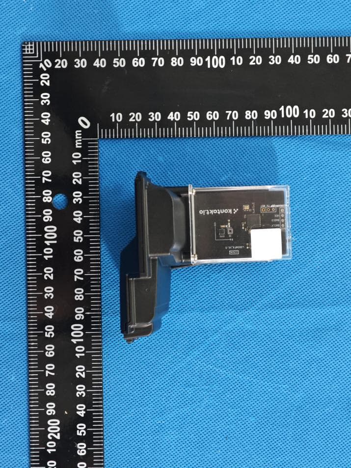
2ADAO-KHWSN301F001
Aug 25, 2026Dispensor Beacon ES10
Equipment Class
DTS - Digital Transmission System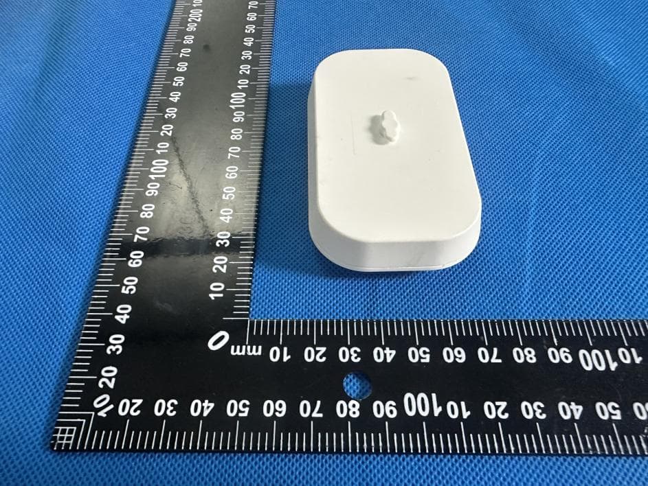
2ADAO-KHWSN300F001
Aug 24, 2026Universal Dispensor Beacon
Equipment Class
DTS - Digital Transmission System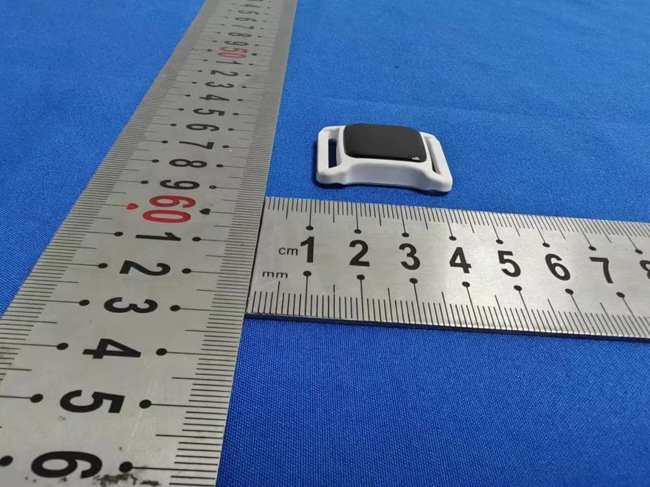
2ADAO-KHWBC701F001
Jul 18, 2024Nano Tag IR
Equipment Class
DTS - Digital Transmission System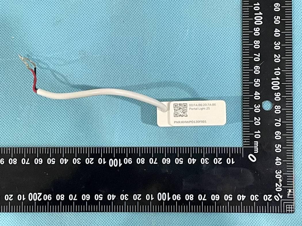
2ADAO-KHWPO130F001
Apr 01, 2024Portal Light 2 IR
Equipment Class
DTS - Digital Transmission System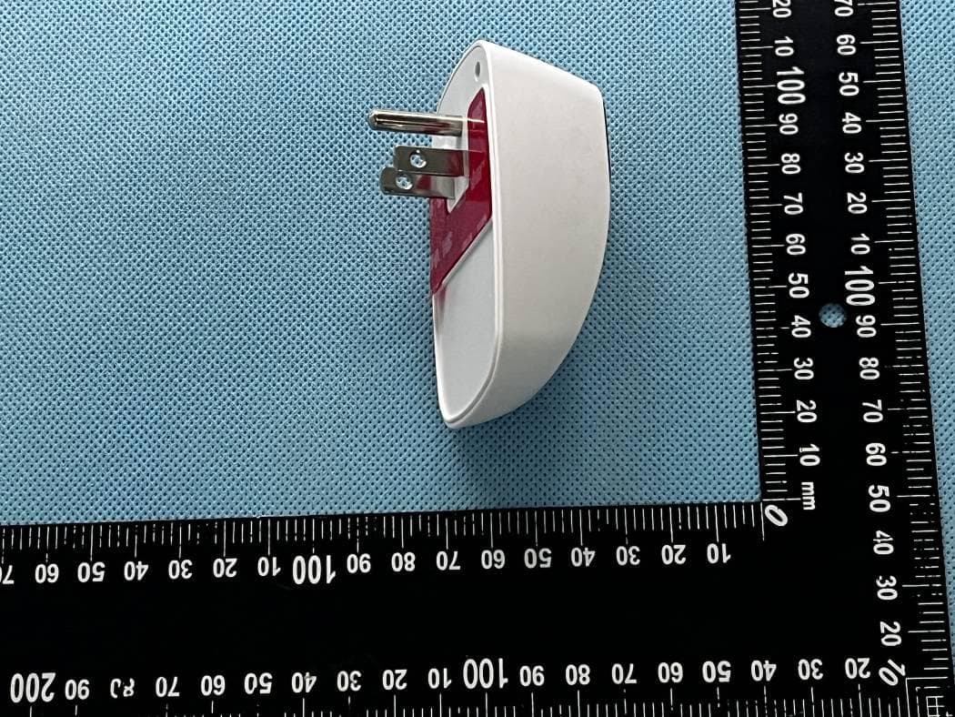
2ADAO-KHWPO120F001
Jan 11, 2024Portal Light 2
Equipment Class
DTS - Digital Transmission System