2ADAOB220Kontakt Beacon
Kontakt Micro-Location Sp. z o.o.
Click to zoom
Application Details
- Equipment Class
- DTS - Digital Transmission System
- Date of Grant
- Feb 19, 2015
- Application Purpose
- Original Equipment
- Date of Application
- Feb 19, 2015
- Equipment Note
- Kontakt Beacon
- Frequency Range
- 2402.00000000 - 2480.00000000
- Country
- Poland
Documents & Files
Document Text
Text extracted from the exhibit documents filed with the FCC. Open a document above to read the original.
Users Manual
Copyright © 2014 Kontakt Micro-Location LLC. All rights reserved. Kontakt Micro-Location kontakt.io email: [email protected] Kontakt Beacon: User Manual Turning on and maintenance Kontakt Beacons are maintenance-free devices. They work constantly and they are ready to be used in ‘out of the box’ manner. There is no need to turn the beacon on or activate it in any way. They are ready to perform once programmed and assembled. In case of possible malfunction, their users are advised to contact technical support to receive proper replacements (email: [email protected]). Replacement policy also applies to performance faults caused by low battery after certain operation time. The name of the device and manufacturer are mentioned on the back of beacons’ casings. Installation Kontakt Beacons can be fixed on the wall by using a proper nail or a screw by means of a specially created hole in the back flip. A user needs to make sure to adhere a Beacon to the mounting surface firmly. Alternatively, one can use double-side adhesive tape and stick it to a flat and smooth surface. In such configuration it’s important to follow the proper vertical orientation. Beacons should be placed the way they are hanged when mounted using nails (mounting hole must be on top). It’s also important to be aware of the fact that Beacons are installed in the right direction, meaning the manufacturer logo must be on the opposite form the sticky tape and the mounting surface. If beacons are installed this way, a user takes responsibility for choosing the right adhesive that is able to keep beacons in proper places. We recommend using at least 4cm 2 of the sticky tape with viscosity of 10N/cm. Kontakt Beacon: User manual Page 2 of 3 WARNING Opening beacons or fixing them is strictly forbidden. Kontakt Beacons contain electronic elements and batteries which should be properly disposed. If one ever needs to utilize beacons, it is advisable to contact the manufacturer first. Switching the original battery with one of a different type might cause a risk of explosion. FCC (USA) / IC (Canada) Compliance Statements FCC Compliance This device complies with Part 15 of the FCC Rules. Operation is subject to the following two conditions: (1) This device may not cause harmful interference, and (2) This device must accept any interference received, including interference that may cause undesired operation. Any changes or modifications which are not expressly approved by Kontakt Micro-Location Sp. z o.o., could void the user’s authority to operate the equipment. Kontakt Beacon has been designed and complies with the safety requirements for portable (<20cm) RF exposure in accordance with FCC rule part 2.1093 and KDB 447498 D01 as demonstrated in the RF exposure analysis. Installers must ensure that this device must not be co-located or operated in conjunction with any other antenna or transmitter except in accordance with FCC multi-transmitter product procedures. IC Compliance This device complies with Industry Canada license-exempt RSS standard(s). Operation is subject to the following two conditions: (1) This device may not cause interference, and (2) This device must accept any interference, including interference that may cause undesired operation of the device. Kontakt Beacon: User manual Page 3 of 3 Kontakt Beacon has been designed and complies with the safety requirements for RF exposure in accordance with RSS-102 as demonstrated in the RF exposure analysis. Conformité IC Cet appareil est en conformité avec les normes exonerés de license d'Industrie Canada. L'utilisation se soumise aux conditions suivantes: (1) Cet appareil ne peut pas provoquer des interférences. (2) Cet appareil doit accepter tous les interférences, y compris des interférences capables de provoquer un fonctionement intempestif. Kontakt Beacon est conçu en conformité avec les exigences de sécurité pour l'exposition aux rayonnements radioelectriques selon RSS-102, comme démontré dans l'analyse de l'exposition aux rayonnements radioelctriques.
External Photos
External Photos Top View Bottom View Side View All 4 side views are the same
Internal Photos
Internal Photos PCB located in the mounting PCB Top View ANTENNA PCB Bottom View PCB Side View Metal structures on the bottom are for holding the battery in place. It is a positive and a negative connection.
RF Exposure Info
RF Exposure Considerations for the Kontakt Micro-Location Sp z o.o. Beacon FCC ID: 2ADAOB220 Analysis for FCC SAR Test Exemption The FCC requires that the device meet the requirements of KDB 447498 D01 v05r02 to be eligible for SAR test exemption. The Kontakt Beacon Bluetooth Low Energy device operates in the 2400 to 2480MHz operating bands. The following FCC Rule Parts and procedures are applicable: Part 2.1093 – Radiofrequency radiation exposure evaluation: portable devices Part 15.247(b)(3) - For systems using digital modulation in the 902–928 MHz, 2400– 2483.5 MHz, and 5725–5850 MHz bands: 1 Watt. Part 15.247(b)(4) - The conducted output power limit specified in paragraph (b) of this section is based on the use of antennas with directional gains that do not exceed 6 dBi. KDB447498 D01 Mobile and Portable Devices RF Exposure Procedures and Equipment Authorisation Policies SAR Exemption Calculation The following formula as given in KDB 487497 D01 v05r02, section 4.3.1 is used to calculate if the device meets the FCC SAR exemption requirements. The 1-g and 10-g SAR test exclusion thresholds for 100 MHz to 6 GHz at test separation distances ≤ 50 mm are determined by: [(max. power of channel, including tune-up tolerance, mW)/(min. test separation distance, mm)] * [√f(GHz)] ≤ 3.0 for 1-g SAR and ≤ 7.5 for 10-g extremity SAR, where • f(GHz) is the RF channel transmit frequency in GHz • Power and distance are rounded to the nearest mW and mm before calculation • The result is rounded to one decimal place for comparison Parameters Max output conducted power: 8.0dBm (6.31mW) {from Tune Up Spec.} Separation distance: ≤ 5mm {in accordance with KDB 447498 D01 section 4.3.1, point 1)} Frequency: 2.402GHz Calculation At 5mm Separation distance (6.31mw / 5mm) x √ (2.480) ≤ 3 1.26 x 1.58 = 2.0 (rounded to one decimal place as per KDB requirement) 2.0 is < 3.0 limit for 1-g head SAR Conclusion Thus for portable usage, the SAR exclusion condition is fulfilled and SAR evaluation is not required for a separation distance of 5mm or more.
Test Report
UL VS LTD Pavilion A, Ashwood Park, Ashwood Way, Basingstoke, Hampshire, RG23 8BG, UK Telephone: +44 (0)1256 312000 Facsimile: +44 (0)1256 312001 TEST REPORT Test Report No. : UL-RPT-RP10437304JD01A Manufacturer : Kontakt Micro-Location Sp. z o.o. Model No. : B220 FCC ID : 2ADAOB220 IC Certification No. : 12413A-B220 Technology : Bluetooth – Low Energy Test Standard(s) : FCC Parts 15.209(a) & 15.247, Industry Canada RSS-210 A8.2(a), A8.2(b), A8.4(4) & A8.5 and RSS- Gen 4.6.1, 4.6.2, 4.8 & 4.9 1. This test report shall not be reproduced in full or partial, without the written approval of UL VS LTD. 2. The results in this report apply only to the sample(s) tested. 3. The sample tested is in compliance with the above standard(s). 4. The test results in this report are traceable to the national or international standards. 5. Version 1.0. Date of Issue: 27 January 2015 Checked by: pp Ian Watch Senior Engineer, Radio Laboratory Issued by : pp John Newell Quality Manager, UL VS LTD This laboratory is accredited by UKAS. The tests reported herein have been performed in accordance with its terms of accreditation. The Bluetooth ® word mark and logos are owned by the Bluetooth SIG, Inc. and any use of such marks by UL VS LTD is under licence. Other trademarks and trade names are those of their respective owners. TEST REPORT SERIAL NO: UL-RPT-RP10437304JD01A VERSION 1.0 ISSUE DATE: 27 JANUARY 2015 Page 2 of 29 UL VS LTD This page has been left intentionally blank. TEST REPORT SERIAL NO: UL-RPT-RP10437304JD01A VERSION 1.0 ISSUE DATE: 27 JANUARY 2015 UL VS LTD Page 3 of 29 Table of Contents 1. Customer Information ................................................................................................................ 4 2. Summary of Testing ................................................................................................................... 5 2.1. General Information 5 2.2. Summary of Test Results 6 2.3. Methods and Procedures 6 2.4. Deviations from the Test Specification 6 3. Equipment Under Test (EUT) .................................................................................................... 7 3.1. Identification of Equipment Under Test (EUT) 7 3.2. Description of EUT 7 3.3. Modifications Incorporated in the EUT 7 3.4. Additional Information Related to Testing 8 3.5. Support Equipment 8 4. Operation and Monitoring of the EUT during Testing ............................................................. 9 4.1. Operating Modes 9 4.2. Configuration and Peripherals 9 5. Measurements, Examinations and Derived Results ...............................................................10 5.1. General Comments 10 5.2. Test Results 11 5.2.1. Transmitter Minimum 6 dB Bandwidth 11 5.2.2. Transmitter 99% Occupied Bandwidth 13 5.2.3. Transmitter Maximum Peak Output Power 15 5.2.4. Transmitter Radiated Emissions 17 5.2.5. Transmitter Band Edge Radiated Emissions 24 6. Measurement Uncertainty ........................................................................................................28 7. Report Revision History ...........................................................................................................29 TEST REPORT SERIAL NO: UL-RPT-RP10437304JD01A VERSION 1.0 ISSUE DATE: 27 JANUARY 2015 Page 4 of 29 UL VS LTD 1. Customer Information Company Name: Kontakt Micro-Location Sp. z o.o. Address: Ul. Zulowska 43A 31-436 Krakow Poland TEST REPORT SERIAL NO: UL-RPT-RP10437304JD01A VERSION 1.0 ISSUE DATE: 27 JANUARY 2015 UL VS LTD Page 5 of 29 2. Summary of Testing 2.1. General Information Specification Reference: 47CFR15.247 Specification Title: Code of Federal Regulations Volume 47 (Telecommunications): Part 15 Subpart C (Intentional Radiators) - Section 15.247 Specification Reference: 47CFR15.209 Specification Title: Code of Federal Regulations Volume 47 (Telecommunications): Part 15 Subpart C (Intentional Radiators) – Section 15.209 Specification Reference: RSS-GEN Issue 3 December 2010 Specification Title: General Requirements and Information for the Certification of Radio Apparatus Specification Reference: RSS-210 Issue 8 December 2010 Specification Title: Licence-exempt Radio Apparatus (All Frequency Bands): Category I Equipment. Site Registration: FCC: 209735; Industry Canada: 3245B-2 Location of Testing: UL VS LTD, Unit 3 Horizon, Wade Road, Kingsland Business Park, Basingstoke, Hampshire, RG24 8AH, United Kingdom Test Dates: 24 September 2014 to 26 September 2014 TEST REPORT SERIAL NO: UL-RPT-RP10437304JD01A VERSION 1.0 ISSUE DATE: 27 JANUARY 2015 Page 6 of 29 UL VS LTD 2.2. Summary of Test Results FCC Reference (47CFR) IC Reference Measurement Result Part 15.247(a)(2) RSS-Gen 4.6.2 RSS-210 A8.2(a) Transmitter Minimum 6 dB Bandwidth N/A RSS-Gen 4.6.1 Transmitter 99% Occupied Bandwidth Part 15.247(e) RSS-210 A8.2(b) Transmitter Power Spectral Density Note 2 Part 15.247(b)(3) RSS-Gen 4.8 RSS-210 A8.4(4) Transmitter Maximum Peak Output Power Part 15.247(d)/ 15.209(a) RSS-Gen 4.9 RSS-210 A8.5 Transmitter Radiated Emissions Part 15.247(d)/ 15.209(a) RSS-Gen 4.9 RSS-210 A8.5 Transmitter Band Edge Radiated Emissions Key to Results = Complied = Did not comply Note(s): 1. Tested and reported in UL Report UL-EMC-RP10437304JD02A. 2. In accordance with FCC KDB 558074 Section 10.1, PSD is not required if the maximum conducted output power is less than the PSD limit of 8 dBm / 3 kHz. The PSD level is therefore deemed to be equal to the measured total output power. 2.3. Methods and Procedures Reference: ANSI C63.4 (2009) Title: American National Standard for Methods of Measurement of Radio-Noise Emissions from Low-Voltage Electrical and Electronic Equipment in the Range of 9 kHz to 40 GHz Reference: ANSI C63.10 (2009) Title: American National Standard for Testing Unlicensed Wireless Devices Reference: KDB 558074 D01 v03r02 June 5, 2014 Title: Guidance for Performing Compliance Measurements on Digital Transmission Systems (DTS) Operating Under 15.247 2.4. Deviations from the T…
Text truncated - open the document above for the full version.
Test Setup Photos
Kontakt Micro-Location Sp. z o.o. FCC ID: 2ADAOB220 UL-RPT-10437304JD01 IC: 12413A-B220 UL VS LTD 1 Test Setup Photographs for the Kontact Beacon 1. Radiated Emissions 1.1 Configuration 1: X Plane Photo 1 Photo 2 Kontakt Micro-Location Sp. z o.o. FCC ID: 2ADAOB220 UL-RPT-10437304JD01 IC: 12413A-B220 1. Photo 3 1.2 Radiated Emissions Configuration 2: Y Plane Photo 1 Kontakt Micro-Location Sp. z o.o. FCC ID: 2ADAOB220 UL-RPT-10437304JD01 IC: 12413A-B220 UL VS LTD 3 Photo 2 1. Photo 3 Kontakt Micro-Location Sp. z o.o. FCC ID: 2ADAOB220 UL-RPT-10437304JD01 IC: 12413A-B220 1.3 Radiated Emissions Configuration 3: Z Plane Photo 1 Photo 2 Kontakt Micro-Location Sp. z o.o. FCC ID: 2ADAOB220 UL-RPT-10437304JD01 IC: 12413A-B220 UL VS LTD 5 Photo 3
Contact Information
Applicant
Joanna Wolczanska(Ms)
Technical Contact
Kontakt Micro-Location Sp. z o.o.Wojciech Gelmuda
[email protected]48 605 320 724
Ul. Stoczniowcow 3 · Krakow · Poland
Non-Technical Contact
Kontakt Micro-Location Sp. z o.o.Tomasz Kolek
Test Firm
UL VS LtdDarren Rust
Technical Specifications
| # | Rule Parts | Frequency Range | Power Output |
|---|---|---|---|
| 1 | 15C | 2.40 GHz - 2.48 GHz | 1.40 mW |
Other Applications from Kontakt Micro-Location Sp. z o.o.
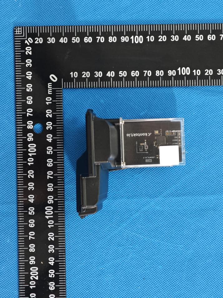
2ADAO-KHWSN301F001
Aug 25, 2026Dispensor Beacon ES10
Equipment Class
DTS - Digital Transmission System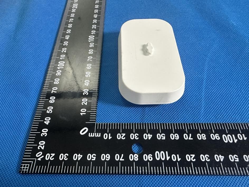
2ADAO-KHWSN300F001
Aug 24, 2026Universal Dispensor Beacon
Equipment Class
DTS - Digital Transmission System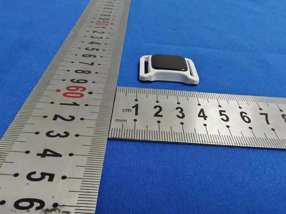
2ADAO-KHWBC701F001
Jul 18, 2024Nano Tag IR
Equipment Class
DTS - Digital Transmission System
2ADAO-KHWPO130F001
Apr 01, 2024Portal Light 2 IR
Equipment Class
DTS - Digital Transmission System
2ADAO-KHWPO120F001
Jan 11, 2024Portal Light 2
Equipment Class
DTS - Digital Transmission System