2ADLL-1103233BMODULE SPEAKER LED DRIVER
Broan-NuTone LLC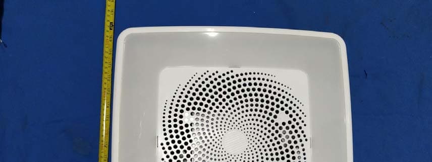
Click to zoom
Application Details
- Equipment Class
- DTS - Digital Transmission System
- Date of Grant
- Apr 16, 2021
- Application Purpose
- Original Equipment
- Date of Application
- Apr 16, 2021
- Equipment Note
- MODULE SPEAKER LED DRIVER
- Frequency Range
- 2402.00000000 - 2480.00000000
- Company
- Broan-NuTone LLC
- Country
- United States
Documents & Files
Document Text
Text extracted from the exhibit documents filed with the FCC. Open a document above to read the original.
Users Manual
MODULE LIGHT SPEAKER User’s Manual 1. Installation 2. Function The MODULE LIGHT SPEAKER: 1.1 Chroma Speaker (120V/60Hz) plays songs through radio frequencies and Bluetooth modules. Turn on the Bluetooth feature on your phone, and you'll instantly find the ChromaComfort-Sensonic Speaker Bluetooth device and click to connect. Open the music player software on the phone and play the music through the Bluetooth speaker. Function Description A. Indicator light Theindictorlightwillturnonbluewhenpressedeffectively,andwillbeoff whenimpressedorpressedformorethan16s. B. Button #1 (for white light) a. Shortpress(<1.2s) Ashortpressforlessthan1.2swillturnthewhitelighton/off. b. Longpress(>=1.2s) Basicfunction:toturnthewhitelighton. Pairingfunction(withinthefirst3minafterthegrillepoweron): PressButton#1formorethan1.2suntilthewhitelighton, thengrilleandwallcontrolgetpairedsuccessfully. The PCBA inside indicator light indicator light Tocancelthepairing,usersneedtokeeppressingButton#1 for more than 10s, until the white light reaches its highest luminanceandgetsdimgradually.Thewhitelightwillflashtwice, whichmeansthepairingiscancelled. IfkeeppressingButton#1formorethan5sthen,thewhite light will get lighter and reach its highest luminance. The white lightwillflashtwice,whichmeansthepairedagain. *Ifthewhitelightisnotonafteralongpressofover1.2sand lessthan5s,whichmeansgrilleandwallcontrolarenotpaired. Usersneedtokeeppressingformorethan5suntilthewhitelight will get lighter and reach its highest luminance, and then grille andwallcontrolgetpairedsuccessfully.Ifuserskeeppressingfor morethan10s,thepairingwillbecancelled. *Ifthewhitelightisnotonafteralongpressofover5s,which means grille and wall control are already paired. If users keep pressing for more than 10s, the pairing will be cancelled. Andif users keep pressing for more than 5s after that, it will startthe pairingagain. C. Button #5 (for colored light) a. Shortpress(<1.2s) Ashortpressforlessthan1.2swillturnthecoloredlighton/off. InRGBsweepmode,thatcanturnoffthecoloredlightonly.If turnedonagain,itwillbeswitchedintoRGBstaticmode. b. Longpress(>=1.2s) Alongpressforover1.2swillturnontheRGBsweepmode. Ifit’salreadyinRGBsweepmode,alongpressforover1.2swill turnitoff. D. Button #7 (for fan) a. Shortpress(<1.2s) Ashortpressforlessthan1.2swillturnthefanon/off. b. Longpress(>=1.2s) A long press for over 1.2s and less than 10s will turn on the fan on/off. Alongpressforover10suntiltheindicatorlightflashtwice,will canceltheBTconnection.10slater,userscanreconnectBT. E. Button #2 (for decreasing luminance) a. Shortpress(<1.2s) Ashortpressforlessthan1.2swilldecreasetheluminancelevelby level,butwon’tturnitoff. b. Longpress(>=1.2s) A short press for more than 1.2s will decrease the luminance gradually,notlevelbylevel,butstillwon’tturnitoff. F. Button #3 (for increasing luminance) a. Shortpress(<1.2s) Ashortpressforlessthan1.2swillincreasetheluminancelevelby leveluntilthehighestluminance. c. Longpress(>=1.2s) Ashortpressformorethan1.2swillincreasetheluminance gradually,notlevelbylevel,untilthehighestluminance. G. Button #4 (for RGB color inverted change) a. Shortpress(<1.2s) WhennotinRGBsweepmode,ashortpressforlessthan1.2swill changeRGBcolorininvertedorderlevelbylevel. WheninRGBsweepmode,ashortpressforlessthan1.2swillstop theRGBsweepmode.Atthistime,anothershortpresswillmakeit inRGBstaticmode. b. Longpress(>=1.2s) WhennotinRGBsweepmode,alongpressformorethan1.2swill changeRGBcolorininvertedordercontinuously. WheninRGBsweepmode,alongpressformorethan1.2swill stoptheRGBsweepmode.Atthistime,anotherlongpresswill makeRGBstaticchangeininvertedordercontinuously. H. Button #4 (for RGB color inverted change) a. Shortpress(<1.2s) WhennotinRGBsweepmode,ashortpressforlessthan1.2swill changeRGBstaticcolorinsequencelevelbylevel. WheninRGBsweepmode,ashortpressforlessthan1.2swillstop theRGBsweepmode.Atthistime,anothershortpresswillmakeit inRGBstaticmode. b. Longpress(>=1.2s) WhennotinRGBsweepmode,alongpressformorethan1.2swill changeRGBcolorinsequencecontinuously. WheninRGBsweepmode,alongpressformorethan1.2swill stoptheRGBsweepmode.Atthistime,anotherlongpresswill makeRGBstaticchangeinsequencecontinuously. Remark: All the functions, except for pairing function, work when grille and wall controlpaired. Button#2andButton#3workonlywhenlighton. Button#4andButton#6workonlywhencoloredlighton. Theoperationsshouldfollowcertainordermentionedabove. Forfunctiondetails,pleaserefertoERD. 3. Warning DISCONNECT POWER AT SERVICE ENTRANCE BEFORE CLEANING OR SERVICING. ADD GRILLE CURRENT TO FAN CURRENT FOR TOTAL CURRENT DRAW. INSTALL ONLY WITH MODELS INDICATED IN THE INSTALLATION INSTRUCTIONS. COUPEZ L’ALIMENTATION AU PANNEAU ÉLECTRIQUE AVANT LES TRAVAUX DE NETTOYAGE OU D’ENTRETIEN. ADDITIONNEZ LA CONSOMMATION DE COURANT DE LA GRILLE À CELLE DU VENTILATEUR POUR OBTENIR L’APPEL TOTAL DE COURANT. S’INSTALLE UNIQUEMENT AVEC LES MODÈLES INDIQUÉS DANS LES DIRECTIVES D’INSTALLATION. FCCWARING Any Changes expressly or modifications not approved by the party responsible for compliance couldvoid the user's authority to operate the equipment. This device complies with part 15 of the FCC Rules. Operation is subject to the following two conditions:(1) This de…
Text truncated - open the document above for the full version.
Attestation Statements
QA-FR-170-B Applicant name: Broan-NuTone LLC ADD: 926 West State Street, Hartford, Wisconsin 53027 United States Telephone No: 262-673-8584 Fax No: 262-673-8647 E-mail: [email protected] Attestation Letter Date: 2021-03-31 FEDERAL COMMUNICATIONS COMMISSION Authorization and Evaluation Division 7435 Oakland Mills Road Columbia, MD 21046 To whom it may concern: We , Broan-NuTone LLC, hereby authorizes Bay Area Compliance Laboratories Corporation to act as a laboratory for testing and test report generation for the following project(s): (declare that the product: MODULE SPEAKER LED DRIVER, FCC ID: 2ADLL-1103233B, model: 1103233) The chip BK3268E supports BT and BLE Mode, But for this device,BLE 2M was disable by software. Sincerely Yours, Client’s signature Printed Name: Darren McArthur Title: Principal Regulatory Engineer
Cover Letter(s)
QA-FR-172-A Applicant name: Broan-NuTone LLC ADD: 926 West State Street, Hartford, Wisconsin 53027 United States Telephone No: 262-673-8584 Fax No: 262-673-8647 E-mail: [email protected] FCC Confidential Authorization Date: 2021-2-2 FEDERAL COMMUNICATIONS COMMISSION Authorization and Evaluation Division 7435 Oakland Mills Road Columbia, MD 21046 Subject: Confidentiality Request regarding application for certification of FCC ID: 2ADLL-1103233B In accordance with Sections 0.457 and 0.459 of the Commission’s Rules, Broan-NuTone LLC hereby requests long-term confidential treatment of information accompanying this application as outlined below: • Block Diagram • Schematics • Operation Description As well as short-term (secrecy cycle: 45 days) confidential treatment of information accompanying this application as outlined below: • Internal Photos • User’s Manual • External Photos • Test Set-up Photos The above materials contain proprietary and confidential information not customarily released to the public. The public disclosure of these materials provides unjustified benefits to its competitors in the market. Sincerely, Signature: Print name: Darren McArthur Title: Principal Regulatory Engineer
External Photos
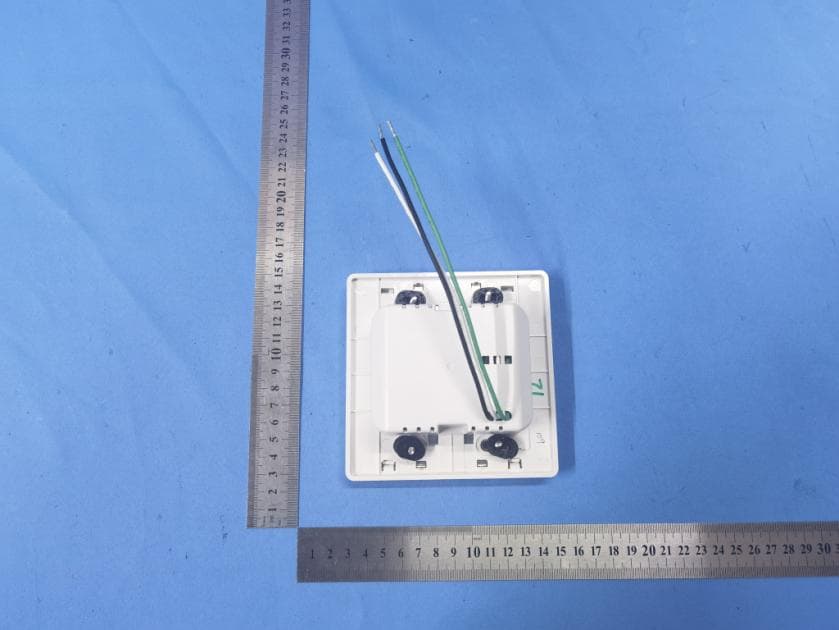
EXHIBIT B - EUT EXTERNAL PHOTOGRAPHS
ID Label/Location Info
Broan-Nutone LLC926 West State Street Hartford, WI 53027 FCC ID: 2ADLL-1103233B IC: 2143B-1103233B DATE CODE CODE DE DATE 1103315D E362499 Class 2 Power Supply MODEL VOLTS Hz AMPS WATTS 1103233 120 60 0.5 28 DISCONNECT POWER AT SERVICE ENTRANCE BEFORE CLEANING OR SERVICING. This device complies with Part 15 of the FCC Rules and RSS-247 of Canada. Operation is subject to the following two conditions: (1) this device may not cause harmful interference, and (2) this device must accept any interference received, including interference that may cause undesired operation. COUPEZ L’ALIMENTATION AU PANNEAU ÉLECTRIQUE AVANT LES TRAVAUX DE NETTOYAGE OU D’ENTRETIEN. Cet appareil est conforme aux normes énoncées à la section 15 des règlements de la FCC et RSS-247 du Canada. Son fonctionnement est assujetti aux conditions suivantes : (1) l’appareil ne doit pas provoquer d’interférences gênantes, et (2) il doit tolérer les interférences reçues, notamment celles susceptibles de provoquer un fonctionnement non souhaité. Hardware Revision: B
Internal Photos
EXHIBIT C - EUT INTERNAL PHOTOGRAPHS
Test Report
FCC PART 15.247 RSS-GEN, ISSUE 5, MARCH 2019 AMENDMENT 1 RSS-247, ISSUE 2, FEBRUARY 2017 TEST REPORT For Broan‐NuTone LLC 926 West State Street Hartford Wisconsin 53027 United States Report Type: Original Report Product Name: MODULE SPEAKER LED DRIVER Report Number: RDG210202050-00B Re port Date: 2021-03-08 Reviewed By: Ivan Cao Assistant Manager Test Laboratory: Bay Area Compliance Laboratories Corp. (Dongguan) No.12, Pulong East 1 st Road, Tangxia Town, Dongguan, Guangdong, China Tel: +86-769-86858888 Fax: +86-769-86858891 www.baclcorp.com.cn FCC ID: 2ADLL-1103233B IC: 2143B-1103233B Bay Area Compliance Laboratories Corp. (Dongguan) Report No.: RDG210202050-00B Page 2 of 37 TABLE OF CONTENTS GENERAL INFORMATION ....................................................................................................................................... 4 PRODUCT DESCRIPTION FOR EQUIPMENT UNDER TEST (EUT) ..................................................................................... 4 OBJECTIVE ................................................................................................................................................................... 4 TEST METHODOLOGY .................................................................................................................................................. 4 MEASUREMENT UNCERTAINTY .................................................................................................................................... 5 TEST FACILITY ............................................................................................................................................................. 5 DECLARATIONS ............................................................................................................................................................ 5 SYSTEM TEST CONFIGURATION .......................................................................................................................... 6 DESCRIPTION OF TEST CONFIGURATION ...................................................................................................................... 6 EQUIPMENT MODIFICATIONS ....................................................................................................................................... 6 EUT EXERCISE SOFTWARE .......................................................................................................................................... 6 EQUIPMENT MODIFICATIONS ....................................................................................................................................... 7 BLOCK DIAGRAM OF TEST SETUP ................................................................................................................................ 7 SUMMARY OF TEST RESULTS ............................................................................................................................... 8 FCC §15.247 (i) & §1.1310 & §2.1091- MAXIMUM PERMISSIBLE EXPOSURE (MPE) ......................................... 9 APPLICABLE STANDARD .............................................................................................................................................. 9 RSS-102 § 2.5.2 - EXEMPTION LIMITS FOR ROUTINE EVALUATION – RF EXPOSURE EVALUATION10 APPLICABLE STANDARD ............................................................................................................................................ 10 FCC §15.203 & RSS-GEN CLAUSE 6.8 - ANTENNA REQUIREMENT ............................................................. 11 APPLICABLE STANDARD ............................................................................................................................................ 11 ANTENNA INFORMATION AND CONNECTOR CONSTRUCTION ..................................................................................... 11 FCC §15.207 (a) & RSS-GEN CLAUSE 8.8– AC LINE CONDUCTED EMISSIONS ......................................... 12 APPLICABLE STANDARD ............................................................................................................................................ 12 EUT SETUP ................................................................................................................................................................ 12 EMI TEST RECEIVER SETUP ....................................................................................................................................... 12 TEST PROCEDURE ...................................................................................................................................................... 12 CORRECTED AMPLITUDE & MARGIN CALCULATION ................................................................................................. 13 TEST EQUIPMENT LIST AND DETAILS ......................................................................................................................... 13 TEST DATA ................................................................................................................................................................ 14 FCC §15.209, §15.205, §15.247(d) & RSS-247 CLAUSE 5.5, RSS-GEN CLAUSE 8.10- SPURIOUS EMISSIONS ................................................................................................................................................................. 16 APPLICABLE STANDARD ............................................................................................................................................ 16 EUT SETUP ................................................................................................................................................................ 16 EMI TEST RECEIVER & SPECTRUM ANALYZER SETUP .............................................................................................. 17 TEST PROCEDURE ........................................................................................…
Text truncated - open the document above for the full version.
Test Setup Photos
EXHIBIT D - TEST SETUP PHOTOGRAPHS Conducted Emissions Front View Conducted Emissions Side View Radiated Emission Below 1GHz View Radiated Emission Above 1GHz View
Contact Information
Applicant
Darren McArthur(Principal Regulatory Engineer)
Test Firm
Bay Area Compliance Laboratories Corp.(Dongguan)David Zhang
[email protected]0086 0769 86858888
Technical Specifications
| # | Rule Parts | Frequency Range | Power Output |
|---|---|---|---|
| 1 | 15C | 2.40 GHz - 2.48 GHz | 2.00 mW |
Other Applications from Broan-NuTone LLC
2ADLL-1110725
Feb 01, 2023Hardwired Room Sensor
Equipment Class
DTS - Digital Transmission System
2ADLL-1102136B
Apr 12, 2021MODULE LIGHT SPEAKER
Equipment Class
DSS - Part 15 Spread Spectrum Transmitter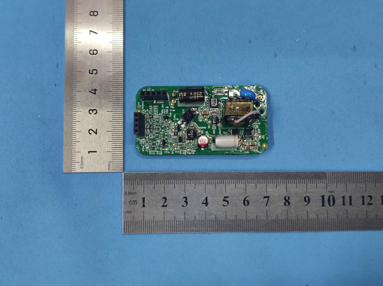
2ADLL-1103434
Dec 24, 2020Wall control
Equipment Class
DTS - Digital Transmission System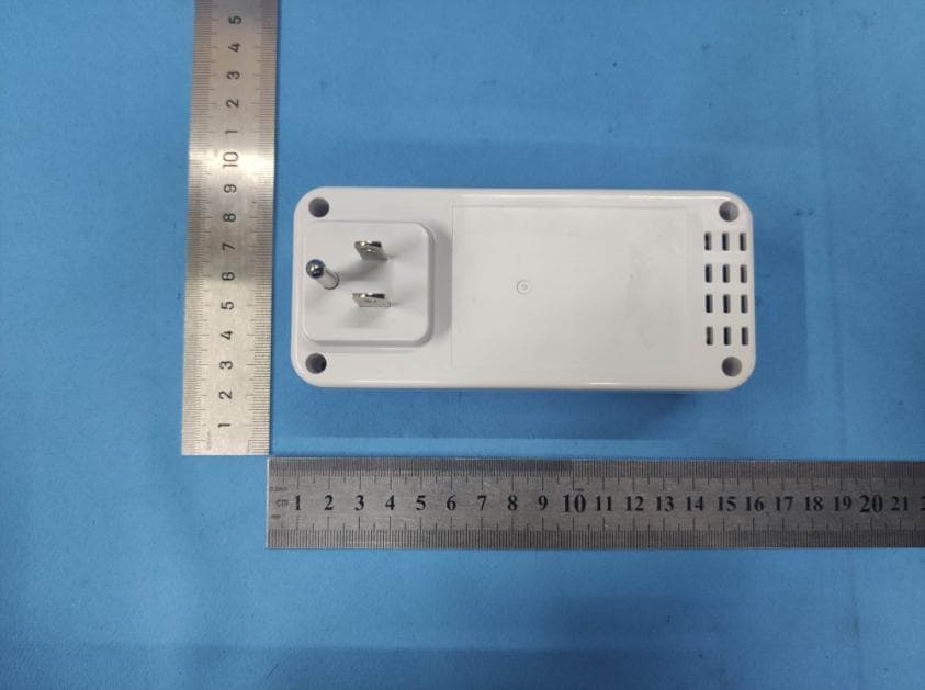
2ADLL-1103435
Dec 23, 2020Smart Plug
Equipment Class
DTS - Digital Transmission System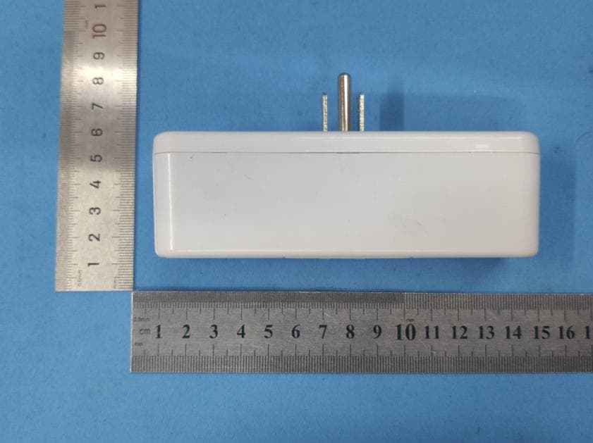
2ADLL-1103436
Dec 22, 2020Smart Plug
Equipment Class
DTS - Digital Transmission System