2ADLL-1103436Smart Plug
Broan-NuTone LLC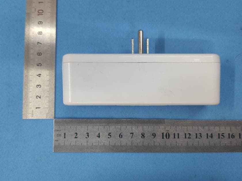
Click to zoom
Application Details
- Equipment Class
- DTS - Digital Transmission System
- Date of Grant
- Dec 22, 2020
- Application Purpose
- Original Equipment
- Date of Application
- Dec 21, 2020
- Equipment Note
- Smart Plug
- Frequency Range
- 2402.00000000 - 2480.00000000
- Company
- Broan-NuTone LLC
- Country
- United States
Documents & Files
Document Text
Text extracted from the exhibit documents filed with the FCC. Open a document above to read the original.
Users Manual
Overture TM SMART PLUG INCLUDED Smart Plug Part No. 1103436 User Manual Quick Start Guide 1103417A For Warranty Statement, Service Parts, Technical Support, or to Register your product, please visit our website or call: In the United States - Broan-NuTone.com 800-558-1711. In Canada - Broan.ca or NuTone.ca 877-896-1119 CONTROL SPECIFICATIONS • cULus Listed • 120 VAC 60 Hz Line Power • Requires NEMA 5-15R or 5-20R Receptacle • Maximum load 15A Resistive, 15A Inductive, ½ HP Motor, 3A Incandescent • Dry Contact Class 2 - 24VAC, 60Hz or 12VDC, 40VA Max Load • Operating temperature: 32-95°F (0-35°C) • Purpose of Control: Operating Control • Rated impulse voltage: 1500 V SAFETY TO REDUCE THE RISK OF FIRE, ELECTRIC SHOCK, OR INJURY TO PERSONS, OBSERVE THE FOLLOWING: 1. Before installing and connecting the Smart Plug, switch power off at the service panel and lock the service disconnecting means to prevent power from being switched on accidentally. When the service disconnecting means cannot be locked, securely fasten a prominent warning device, such as a tag, to the service panel. CAUTION: Risk of Electric Shock - More than one disconnect switch may be required to de-energize the equipment before servicing. 2. All electrical work must be done in accordance with local codes, ordinances, or National Electrical Code, as applicable, including fire-rated construction codes and standards. FOR SAFETY, THIS PRODUCT MUST BE GROUNDED. If you are unfamiliar with methods of installing electrical wiring, secure the services of a qualified electrician. 3. Use copper wire only. 4. When cutting or drilling into wall or ceiling, do not damage electrical wiring or other hidden utilities. 5. To prevent serious injury from electrical shock or damage to electrical components - DO NOT WIRE HOT! 6. Install only in a UL Listed NEMA 5-15R or NEMA 5-20R receptacle. The socket-outlet shall be installed near the equipment and shall be easily accessible. a. NOTE: This device shall not be used in combination with a wall switch controlled receptacle. 7. The automatic operation feature is Type 1 action, according to UL 60730-1. 8. The enclosure protection rating is IP20. 9. The product is Pollution Degree 2, which is intended to be used in a household environment or similar. 10. The devices are not intended for use in locations where the temperature may be less than actual room conditions, such as unheated warehouses or garages. 11. Avoid water and wet locations. Keep the device away from water, fire, excessive humidity, or hot environments. 12. Do not use the device where wireless devices are not allowed. 13. For passthrough devices, plug the power strips into the integrated electrical sockets of the devices, but devices of the same or another type not be stacked in normal use. 14. Do not attempt to disassemble, repair, or modify the device. Don’t disassemble the product, or make repairs yourself. You run the risk of electric shock and voiding the limited warranty. If you need service, please contact us. HRV/ERV INSTALLATION 1. Turn off the power and lockout the service panel before wiring the control to your Fresh Air System. 2. Verify Smart Plug orientation before installation. Note “TOP” direction shown on the Smart Plug label. 3. Location Notes: a. Place your Smart Plug within the range of your Wi-Fi router or access point (approximately 100 feet). b. Avoid physical obstructions and radio interference in the surrounding area. 4. Make electrical connections following the diagrams provided below and in the Broan-NuTone Overture TM App using appropriate wiring for the application. Use wire nuts. Make sure both the Smart Plug and the Fresh Air System are properly grounded. Wire terminals accept #20 AWG to #16 AWG solid or stranded wire suitable for at least 75°C. a. Strip wire to 0.5 " length, press the wire release mechanism, and insert the bare wire into the screw terminal opening. Make sure the wire is seated as far into the terminal is possible. b. Release the wire release mechanism making sure wire remains under the clamp. c. Note: Do not reuse wire formed into a “J” loop or wrapped around screw threads. The wire terminal is designed for the straight insertion of stripped wire for proper mechanical and electrical connection. 5. Route wires to HRV/ERV. Regulatory Information The Overture TM Smart Plug 1103436 is certified to comply with applicable FCC and IC rules and regulations governing RF and EMI emissions. Refer to 1103436. This device complies with Part 15 of the FCC Rules. Operation is sub- ject to the following two conditions: (1) This device may not cause harmful interference, and (2) This device must accept any interference received, including interference that may cause undesired operation. FCC Notice This equipment has been tested and found to comply with the limits for a Class B digital device, pursuant to Part 15 of the FCC Rules. These limits are designed to provide reasonable protection against harmful interference in a residential installation. This equipment generates, uses, and can radiate radio frequency energy and, if not installed and used in accordance with the instructions may cause harmful interference to radio communications. However, there is no guarantee that interference will not occur in a particular installation. If this equipment does cause harmful interference to radio or television reception, which can be determined by turning the equipment off and on, the user is encouraged to try to correct the interference by one or more of the following measures: • Reorient or relocate the receiving antenna. • Increase the separation between the equipment and receiver. • Connect the equipment into an outlet on a circuit different from that to which the receiver is connected. • Consult the dealer or an experienced radio/TV technician to help. Changes or modifications not expressly approved by the party responsible for compliance could void the user’s authority to operate the equipment. ISED Complianc…
Text truncated - open the document above for the full version.
Cover Letter(s)
Broan-NuTone LLC DATE : 2020-11-16 Equipment Autorisation Division Federal Communications Commission 7435 Oakland Mills Road Columbia, MD 21046 FCC ID: 2ADLL-1103436 Product Name: Smart Plug Request for Confidentiality Pursuant to Sections 0.457 and 0.459 of the commissions rules, we hereby request that the following documents be held confidential: • Schematics • Block diagram • Operation description These materials contain trade secrets and proprietary information and are not customarily released to the public. The public disclosure of this information might be harmful to the company and provide unjustified benefits to our competitors. Signature: Name: Darren McArthur Title: Principal Regulatory Engineer Company: Broan-NuTone LLC
Cover Letter(s)
DATE:2020-11-16 Federal Communications Commission Authorization & Evaluation Division 7345 Oakland Mills Road Columbia, Maryland 21046 Authority to Act asAgent On our behalf, I appoint Jason Wu of Global United Technology Services Co., Ltd.andNo. 123- 128, Tower A, Jinyuan Business Building, No.2, Laodong Industrial Zone, Xixiang Road, Baoan District, Shenzhen, Guangdong, China to act as our agent in the preparation of this application for equipment certification. I certify that submitted documents properly describe the device or system for which equipment certification is sought. I also certify that each unit manufactured, imported or marketed, as defined in the Federal Communications Commission’s regulations will have affixed to it a label identical to that submitted for approval with this application. For instances where our authorized agent signs the application for certification on our behalf, I acknowledge that all responsibility for complying with the terms and conditions for certification, still resides with Broan-NuTone LLC and 926 West State Street, Hartford, Wisconsin 53027, United States Signature: Name: Darren McArthur Title: Principal Regulatory Engineer Company: Broan-NuTone LLC
ID Label/Location Info
4.Material: 3m7816 5单排卷装来料。 6. F: Shaft Inner Diameter=75mm 7. G: ≤Φ150mm
RF Exposure Info
FCC ID: 2ADLL-1103436 RF Exposure Evaluation FCC Limits The criteria listed in the following table shall be used to evaluate the environment impact of human exposure to radio frequency (RF) radiation as specified in 1.1307(b) Limits for Maximum Permissible Exposure (MPE) Frequency range (MHz) Electric field strength (V/m) Magnetic field strength (A/m) Power density (mW/cm 2 ) Averaging time (minutes) (A) Limits for Occupational/Controlled Exposures 0.3–3.0 614 1.63 *(100) 6 3.0–30 1842/f 4.89/f *(900/f 2 )6 30–300 61.4 0.163 1.0 6 300–1500 f/300 6 1500–100,000 5 6 (B) Limits for General Population/Uncontrolled Exposure 0.3–1.34 614 1.63 *(100) 30 1.34–30 824/f 2.19/f *(180/f 2 )30 30–300 27.5 0.073 0.2 30 300–1500 f/1500 30 1500–100,000 1.0 30 f = frequency in MHz Friis transmission formula: Pd = (Pout*G)/(4*pi*r 2 ) Where Pd = power density in mW/cm 2 , Pout = output power to antenna in mW; G = gain of antenna in linear scale, Pi = 3.1416; R = distance between observation point and center of the radiator in cm Pd id the limit of MPE, 1 mW/cm 2 . If we know the maximum gain of the antenna and the total power input to the antenna, through the calculation, we will know the distance r where the MPE limit is reached. Test Procedure Software provided by client enabled the EUT to transmit and receive data at lowest, middle and highest channel individually. FCC ID: 2ADLL-1103436 Test Result of RF Exposure Evaluation Wifi Channel Output power to antenna (mW) Power Density at R=20cm (mW/cm 2 ) Limit (mW/cm 2 )Result Lowest 74.82 0.02114 1.0 PASS Middle 57.68 0.01629 1.0 PASS Highest 39.72 0.01122 1.0 PASS BLE Channel Output power to antenna (mW) Power Density at R=20cm (mW/cm 2 ) Limit (mW/cm 2 )Result Lowest 0.92 0.00026 1.0 PASS Middle 1.07 0.00030 1.0 PASS Highest 1.15 0.00032 1.0 PASS Antenna gain: 1.52dBi
Test Report
Global United Technology Services Co., Ltd. Report No.: GTS202011000032-02 Authorized Signature: Robinson Lo Laboratory Manager This results shown in this test report refer only to the sample(s) tested, this test report cannot be reproduced, except in full, without prior written permission of the company. The report would be invalid without specific stamp of test institute and the signatures of compiler and approver. Page 1 of 40 TEST REPORT Applicant: Broan-NuTone LLC Address of Applicant: 926 West State Street, Hartford, Wisconsin 53027, United States Manufacturer /Factory: Computime Electronics (Shenzhen) Company Limited Address of Manufacturer/Factory: Yuekenguangyu Industrial Park,Kangqiao Road 88#, Danzhutou Community, Nanwan Street office,Longgang District, Shenzhen, China Equipment Under Test (EUT) Product Name: Smart Plug Model No.: 1103436 Trade Mark: Broan-NuTone FCC ID: 2ADLL-1103436 IC: 2143B-1103436 Applicable standards: FCC CFR Title 47 Part 15 Subpart C Section 15.247 RSS-247 Issue 2 RSS-Gen Issue 5 Date of sample receipt: November 04, 2020 Date of Test: November 05-13, 2020 Date of report issued: November 16, 2020 Test Result : PASS * * In the configuration tested, the EUT complied with the standards specified above. Report No.: GTS202011000032-02 Global United Technology Services Co., Ltd. No. 123-128, Tower A, Jinyuan Business Building, No.2, Laodong Industrial Zone, Xixiang Road, Baoan District, Shenzhen, Guangdong, China 518102 Telephone: +86 (0) 755 2779 8480 Fax: +86 (0) 755 2779 8960 Page 2 of 40 2 Version Version No. Date Description 00 November 16, 2020 Original Prepared By: Date: November 16, 2020 Project Engineer Check By: Date: November 16, 2020 Reviewer Report No.: GTS202011000032-02 Global United Technology Services Co., Ltd. No. 123-128, Tower A, Jinyuan Business Building, No.2, Laodong Industrial Zone, Xixiang Road, Baoan District, Shenzhen, Guangdong, China 518102 Telephone: +86 (0) 755 2779 8480 Fax: +86 (0) 755 2779 8960 Page 3 of 40 3 Contents Page 1 COVER PAGE ........................................................................................................................................... 1 2 VERSION .................................................................................................................................................. 2 3 CONTENTS .............................................................................................................................................. 3 4 TEST SUMMARY ..................................................................................................................................... 4 5 GENERAL INFORMATION ...................................................................................................................... 5 5.1 GENERAL DESCRIPTION OF EUT ......................................................................................................... 5 5.2 TEST MODE ........................................................................................................................................ 7 5.3 DESCRIPTION OF SUPPORT UNITS ....................................................................................................... 7 5.4 DEVIATION FROM STANDARDS ............................................................................................................. 7 5.5 ABNORMALITIES FROM STANDARD CONDITIONS ................................................................................... 7 5.6 TEST FACILITY .................................................................................................................................... 7 5.7 TEST LOCATION ................................................................................................................................. 7 5.8 ADDITIONAL INSTRUCTIONS ................................................................................................................. 7 6 TEST INSTRUMENTS LIST ..................................................................................................................... 8 7 TEST RESULTS AND MEASUREMENT DATA .................................................................................... 10 7.1 ANTENNA REQUIREMENT ................................................................................................................... 10 7.2 CONDUCTED EMISSIONS ................................................................................................................... 11 7.3 CONDUCTED OUTPUT POWER ........................................................................................................... 14 7.4 CHANNEL BANDWIDTH & 99% OCCUPY BANDWIDTH .......................................................................... 16 7.5 POWER SPECTRAL DENSITY ............................................................................................................. 18 7.6 SPURIOUS EMISSION IN NON-RESTRICTED & RESTRICTED BANDS ....................................................... 20 7.6.1 Conducted Emission Method ..................................................................................................... 20 7.6.2 Radiated Emission Method ........................................................................................................ 23 7.7 FREQUENCY STABILITY ..................................................................................................................... 38 8 TEST SETUP PHOTO ............................................................................................................................ 40 9 EUT CONSTRUCTIONAL DETAILS ..................................................................................................... 40 Report No.: GTS202011000032-02 Global United Technology Services Co., Ltd. No. 123-128, Tower A, Jinyuan Business Building, No.2, Laodong Industrial Zone, Xixiang Road, Baoan District, Shenzhen, Guangdong, China 518102 Telephone: +86 (0) 755 2779 8480 Fax: +86 (0) 755 2779 8960 Page 4 of 40 4…
Text truncated - open the document above for the full version.
Test Report
Global United Technology Services Co., Ltd. Report No.: GTS202011000032-01 Authorized Signature: Robinson Lo Laboratory Manager This results shown in this test report refer only to the sample(s) tested, this test report cannot be reproduced, except in full, without prior written permission of the company. The report would be invalid without specific stamp of test institute and the signatures of compiler and approver. Page 1 of 50 TEST REPORT Applicant: Broan-NuTone LLC Address of Applicant: 926 West State Street, Hartford, Wisconsin 53027, United States Manufacturer /Factory: Computime Electronics (Shenzhen) Company Limited Address of Manufacturer/Factory: Yuekenguangyu Industrial Park,Kangqiao Road 88#, Danzhutou Community, Nanwan Street office,Longgang District, Shenzhen, China Equipment Under Test (EUT) Product Name: Smart Plug Model No.: 1103436 Trade Mark: Broan-NuTone FCC ID: 2ADLL-1103436 IC: 2143B-1103436 Applicable standards: FCC CFR Title 47 Part 15 Subpart C Section 15.247 RSS-Gen Issue 5 RSS-247 Issue 2 Date of sample receipt: November 04, 2020 Date of Test: November 05-13, 2020 Date of report issued: November 16, 2020 Test Result : PASS * * In the configuration tested, the EUT complied with the standards specified above. Report No.: GTS202011000032-01 Global United Technology Services Co., Ltd. No. 123-128, Tower A, Jinyuan Business Building, No.2, Laodong Industrial Zone, Xixiang Road, Baoan District, Shenzhen, Guangdong, China 518102 Telephone: +86 (0) 755 2779 8480 Fax: +86 (0) 755 2779 8960 Page 2 of 50 2 Version Version No. Date Description 00 November 16, 2020 Original Prepared By: Date: November 16, 2020 Project Engineer Check By: Date: November 16, 2020 Reviewer Report No.: GTS202011000032-01 Global United Technology Services Co., Ltd. No. 123-128, Tower A, Jinyuan Business Building, No.2, Laodong Industrial Zone, Xixiang Road, Baoan District, Shenzhen, Guangdong, China 518102 Telephone: +86 (0) 755 2779 8480 Fax: +86 (0) 755 2779 8960 Page 3 of 50 3 Contents Page 1 COVER PAGE ........................................................................................................................................... 1 2 VERSION .................................................................................................................................................. 2 3 CONTENTS .............................................................................................................................................. 3 4 TEST SUMMARY ..................................................................................................................................... 4 5 GENERAL INFORMATION ...................................................................................................................... 5 5.1 GENERAL DESCRIPTION OF EUT ......................................................................................................... 5 5.2 TEST MODE ........................................................................................................................................ 7 5.3 DESCRIPTION OF SUPPORT UNITS ....................................................................................................... 7 5.4 TEST FACILITY .................................................................................................................................... 7 5.5 TEST LOCATION ................................................................................................................................. 7 5.6 ADDITIONAL INSTRUCTIONS ................................................................................................................. 7 6 TEST INSTRUMENTS LIST ..................................................................................................................... 8 7 TEST RESULTS AND MEASUREMENT DATA .................................................................................... 10 7.1 ANTENNA REQUIREMENT ................................................................................................................... 10 7.2 CONDUCTED EMISSIONS ................................................................................................................... 11 7.3 CONDUCTED PEAK OUTPUT POWER .................................................................................................. 14 7.4 CHANNEL BANDWIDTH & 99% OCCUPY BANDWIDTH .......................................................................... 15 7.5 POWER SPECTRAL DENSITY ............................................................................................................. 20 7.6 SPURIOUS EMISSION IN NON-RESTRICTED & RESTRICTED BANDS ....................................................... 23 7.6.1 Conducted Emission Method ..................................................................................................... 23 7.6.2 Radiated Emission Method ........................................................................................................ 32 7.7 FREQUENCY STABILITY ..................................................................................................................... 47 8 TEST SETUP PHOTO ............................................................................................................................ 50 9 EUT CONSTRUCTIONAL DETAILS ..................................................................................................... 50 Report No.: GTS202011000032-01 Global United Technology Services Co., Ltd. No. 123-128, Tower A, Jinyuan Business Building, No.2, Laodong Industrial Zone, Xixiang Road, Baoan District, Shenzhen, Guangdong, China 518102 Telephone: +86 (0) 755 2779 8480 Fax: +86 (0) 755 2779 8960 Page 4 of 50 4 Test Summary Test Item Section Result Antenna requirement FCC part 15.203/15.247 (c) RSS-Gen Section 6.8 Pass AC Power Line Conducted Emission FCC part 15.207 RSS-Gen Section 8.8 Pass Conducted Peak Output Power FCC part 15.247 (b)(3) RSS-247 Section 5.4(d) Pass Channel Ba…
Text truncated - open the document above for the full version.
Test Setup Photos
Radiated Emission Conducted Emission
Contact Information
Applicant
Darren McArthur(Principal Regulatory Engineer)
Test Firm
Global United Technology Services Co. Ltd.Robinson Lo
Technical Specifications
| # | Rule Parts | Frequency Range | Power Output |
|---|---|---|---|
| 3 | 15C | 2.40 GHz - 2.48 GHz | 1.15 mW |
Other Applications from Broan-NuTone LLC
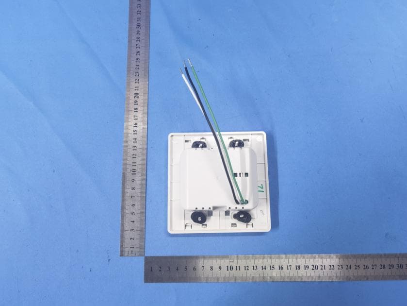
2ADLL-1110725
Feb 01, 2023Hardwired Room Sensor
Equipment Class
DTS - Digital Transmission System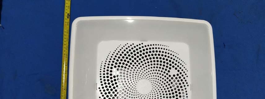
2ADLL-1103233B
Apr 16, 2021MODULE SPEAKER LED DRIVER
Equipment Class
DTS - Digital Transmission System
2ADLL-1102136B
Apr 12, 2021MODULE LIGHT SPEAKER
Equipment Class
DSS - Part 15 Spread Spectrum Transmitter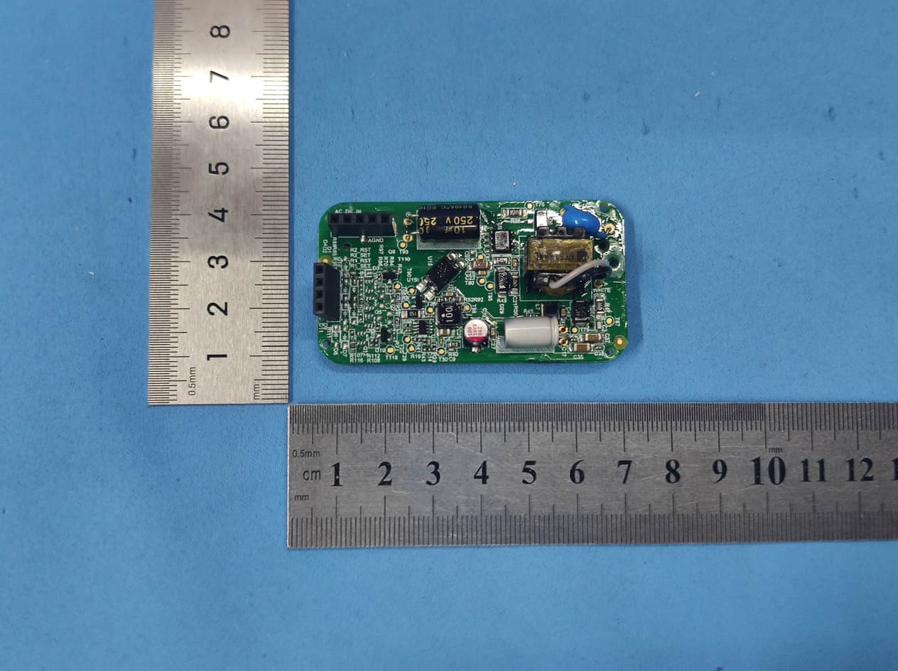
2ADLL-1103434
Dec 24, 2020Wall control
Equipment Class
DTS - Digital Transmission System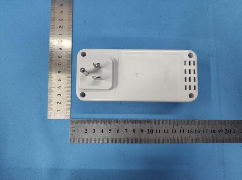
2ADLL-1103435
Dec 23, 2020Smart Plug
Equipment Class
DTS - Digital Transmission System