2ADQFC008TR900TELEMATIC Transceiver
Otodata Wireless Network Inc.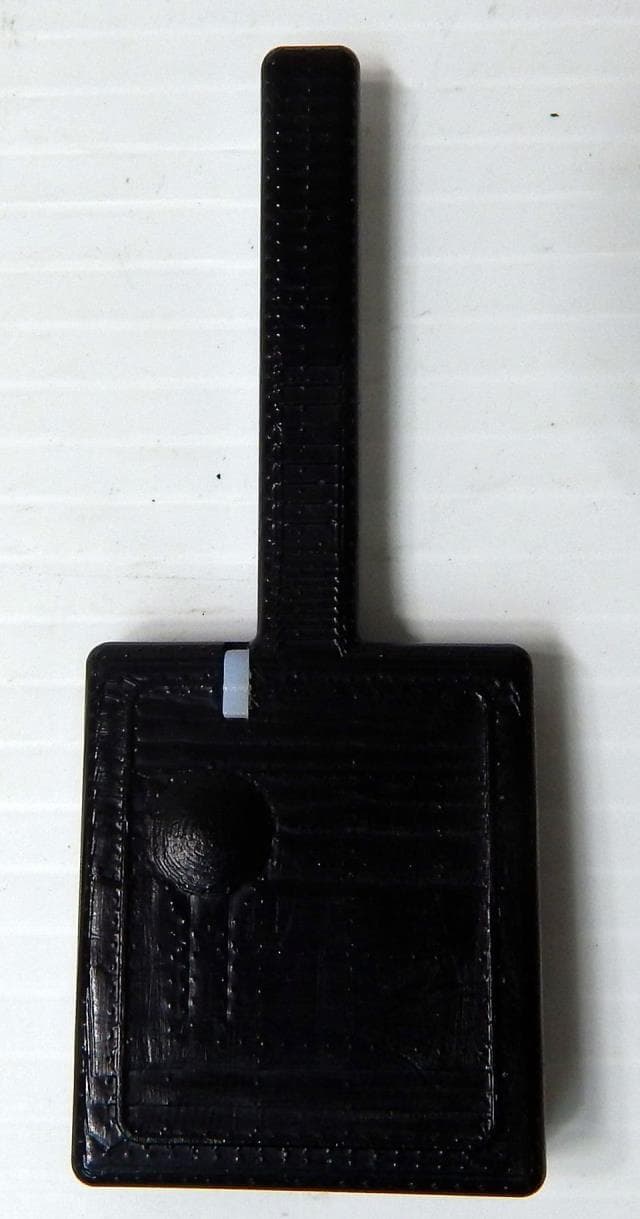
Click to zoom
Application Details
- Equipment Class
- DSS - Part 15 Spread Spectrum Transmitter
- Date of Grant
- Oct 01, 2015
- Application Purpose
- Original Equipment
- Date of Application
- Oct 01, 2015
- Equipment Note
- TELEMATIC Transceiver
- Frequency Range
- 902.24000000 - 927.76000000
- Country
- Canada
Documents & Files
Document Text
Text extracted from the exhibit documents filed with the FCC. Open a document above to read the original.
Users Manual
(+) ALLUMAGE (+) BATTERIE 12V (1) MISE À LA MASSE (1) KLAXON (3) 4 PIN (BLANC) - DBALL 2 - Autostart Pager Port (HRN-RS-1) (2) - ASD-200 - 4X10 4 PIN (BLEU) - AKX - iDatastart - EVO-ONE - ADS-AL-CA - Compustar - DSE (INTV1) (2) +12V Battery (ROUGE) Ground (NOIR) Data (BLANC) Data (BLEU) + Ignition ( JAUNE ) Horn (VERT) Antenne: Longueur du fil 9 pieds Installation: Placer l’antenne à 3 pouces (minimum) de tout obstacle Orientation: Verticale; l’antenne tournée vers le bas (tel qu’indiqué dans le graphique) PAGER PORT / TRIGGER START (-) 4 PIN (NOIR) - EVO-ALL DÉMARREUR ou BYPASS C5040/MS2 RF KIT INPUT (3) 11 2. PROGRAMMER a. Brancher l’unité C5040 b. Attendre la séquence de démarrage c. L’unité est en mode de programmation par défaut lorsqu’elle n’est pas déjà programmée d. La DEL bleue clignote selon le protocole sélectionné : i. ADS (par défault) ii. Fortin iii. Xpresskit iv. Smart Start (PolarStart version H7.0 V6.0 et +) v. Polarstart Pager Legacy vi. Trigger Start (-) e. Appuyer brièvement sur le bouton pour changer le protocole f. Appuyer sur le bouton pendant 2 secondes (la DEL verte clignotera deux fois) pour sauvegarder le protocole sélectionné g. Fortin seulement (Procédure d’apprentissage) : i. Suivre les instructions du démarreur pour activer la programmation d’une télécommande ii. Lorsque la DEL bleue clignote, appuyer brièvement sur le bouton pour envoyer une commande LOCK iii. L’unité C5040 est maintenant enregistrée dans le démarreur iv. Quitter le mode de programmation de télécommande du démarreur h. L’unité C5040 est maintenant en mode « opération ». 3. VALIDER 1. Débrancher le C5040 2. Mettre la clé à la position « Ignition On » 3. Brancher l’unité C5040 4. Attendre la séquence de démarrage 5. L’unité C5040 est maintenant en mode « Test installateur » pendant 15 secondes et la DEL mauve clignote lentement 6. Durant cette periode, mettre la clé en position « Off » pour envoyer une commande UNLOCK 7. L’unité C5040 est maintenant en mode « Normal ». MODE « OPÉRATION » Action / ÉvénementDescription de l’état des DELs Séquence de démarrage DEL rouge, verte et bleue allumées séquentiellement Commande envoyée au démarreur Clignotement rapide de la DEL verte durant 1 seconde Échec d’envoi de commande au démarreur Clignotement rapide de la DEL rouge durant 1 seconde Réinitialisation (maintenir bouton avant de brancher) Clignotement rapide de la DEL orange durant 2 secondes 4. CONFIGURER a. Installez l’app du téléphone intelligent b. Créez une session de client (si elle n’existe pas déjà) c. Allez à «Ajouter un véhicule» d. Entrez le code d’activation e. l’Inscription est complétée 5. LIVRER Déplacer et éteindre le véhicule à l’extérieur dans un endroit dégagé pour permettre au véhicule de s’enregistrer dans l’infrastructure. PIT-STOP Si votre démarreur supporte le mode “Pit-Stop” : 1. Lorsque vous êtes stationnés et que le moteur tourne, appuyer sur le bouton pendant 2 secondes (la DEL verte clignotera deux fois). L’unité C5040 envoie une commande START au démarreur pendant que le moteur tourne, ce qui active le mode « Pit-Stop ». 2. Retirer la clé et sortir du véhicule (le moteur tourne toujours). (1) A utiliser avec EVO-ALL, ADS-AL-CA ou DBALL 2 (2) Unidirectionnel (troubles non disponibles) (3) Optionnel DIRECTIVES D’INSTALLATION C5040/MS2 COMMUNICATEUR TÉLÉMATIQUE Le présent appareil est conforme aux CNR d’Industrie Canada applicables aux appareils radio exempts de licence. L’exploitation est autorisée aux deux conditions suivantes : (1) l’appareil ne doit pas produire de brouillage, et (2) l’utilisateur de l’appareil doit accepter tout brouillage radioélectrique subi, même si le brouillage est susceptible d’en compromettre le fonctionnement. Tout changement ou modification non expressément approuvé par la partie responsable de la conformité risque d’invalider l’autorisation accordée à l’utilisateur d’utiliser cet appareil. Avertissement RF conformité de l’exposition. L’antenne (s) utilisée pour cet émetteur doit être installée pour fournir une distance de séparation d’au moins 20 cm de toutes personnes et ne doit pas être situé à proximité ou fonctionner en conjonction avec une autre antenne ou émetteur. Les utilisateurs et les installateurs doivent recevoir des instructions d’installation de l’antenne et des conditions de fonctionnement du transmetteur satisfaisant le respect de l’exposition aux RF. 1. BRANCHER Le système doit être installé par un professionnel. (+) IGNITION (+) 12V BATTERY (1) GROUND (1) (+) HORN (3) 4 PIN (WHITE) - DBALL 2 - Autostart Pager Port (HRN-RS-1) (2) - ASD-200 - 4X10 4 PIN (BLACK) - EVO-ALL 4 PIN (BLUE) - AKX - iDatastart - EVO-ONE - ADS-AL-CA - Compustar - DSE (INTV1) (2) +12V Battery (RED) Ground (BLACK) Data (WHITE) Data (BLUE) + Ignition (YELLOW) Horn ( GREEN) Antenna: Cord length 9 feet Installation: Place antenna 3 inches (minimum) from any obstructions Orientation: Vertical; antenna facing downwards (as seen in diagram) PAGER PORT / TRIGGER START (-) CAR STARTER or BYPASS RF KIT INPUT (3) C5040/MS2 11 2. PROGRAM a. Connect the C5040 unit b. Wait for the start up sequence c. The module is in programming mode by default if not already programmed d. The blue LED will blink according to the selected protocol: i. ADS (default) ii. Fortin iii. Xpresskit iv. Smart Start (PolarStart version H7.0 V6.0 +) v. Polarstart Pager Legacy vi. Trigger Start (-) e. Briefly press the button to change the protocol f. Press and hold the button for 2 seconds to save the selected protocol g. For Fortin only (learning procedure): i. Enter the transmitter learning mode by following the remote starter instructions ii. Once the transmitter learning mode is entered, the Blue LED will start blinking on the C5040 unit. Briefly press and release the programming button to send a LOCK command to the remote starter iii. The C5040 unit should now be registered with the remote car starter iv. Exit the remote learning mode of the remote car starter h. The C5040 unit is now …
Text truncated - open the document above for the full version.
External Photos
www.nemko.com Nemko Canada Inc., a testing laboratory, is accredited by the Standards Council of Canada. The tests included in this report are within the scope of this accreditation External photos.docx; Date: May 2013 SCC Accredited LAB LAB Accrédité CCN TM ONE WORLDOURAPPROVAL External photos 292050-1RADWL Date of issue: August 10, 2015 Applicant: Otodata Wireless Network Inc. Product: Wireless Telematic device Model: C008TR900 FCC ID: IC Registration number: 2ADQFC008TR900 12649A-C008TR900 Section 1: External photos Report reference ID: -1RADWL Page 2 of 3 Section 1. External photos 1.1 Front view Section 1: External photos Report reference ID: -1RADWL Page 3 of 3 1.2 Rear view
Internal Photos
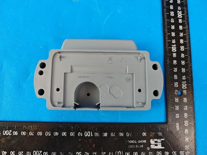
www.nemko.com Nemko Canada Inc., a testing laboratory, is accredited by the Standards Council of Canada. The tests included in this report are within the scope of this accreditation Internal photos.docx; Date: May 2013 SCC Accredited LAB LAB Accrédité CCN TM ONE WORLDOURAPPROVAL Internal photos 292050-2RADWL Date of issue: August 10, 2015 Applicant: Otodata Wireless Network Inc. Product: Wireless Telematic device Model: C008TR900 FCC ID: IC Registration number: 2ADQFC008TR900 12649A-C008TR900 Section 1: Internal photos Report reference ID: -2RADWL Page 2 of 5 Section 1. Internal photos 1.1 Top general view Section 1: Internal photos Report reference ID: -2RADWL Page 3 of 5 1.2 PCB with shieldings on view Section 1: Internal photos Report reference ID: -2RADWL Page 4 of 5 1.3 PCB with removed shieldings view Section 1: Internal photos Report reference ID: -2RADWL Page 5 of 5 1.4 PCB rear view
Operational Description
CONFIDENTIAL & PROPRIETARY C5040 (C008TR900) v.1 TELEMATIC module Technical description of the system; The C5040 (C008TR900) transceiver is an autonomous transceiver that is used primarily for the, control, reading and identification management of assets using RF (radio frequencies). The C5040 (C008TR900) may be used in conjunction with active base station receivers and controlers. The The C5040 (C008TR900) may be affixed to assets with which base stations may communicate in order to collect data. C5040 (C008TR900) capabilities; The C5040 (C008TR900) have been developped in order to provide the following services and functionalites. Data transfer, logging Telemetrie or telematic control Temperature monitoring Humidity monitoring Voltage monitoring Automated inventory management Automated fleet management Internal component and circuit description; The following components are included in the C008TR900 plastic enclosure: 1) Single PCB board 2) Soldered RF shield 3) Fix Antenna (none removable) 4) TX low pass filter & RX band pass filter Operational description Telemetry transceiver Telematic control Highly robust communication protocol Reinforced Easy to install 5) Led indicator The board performs all of the Radio transmit/receive control functions as well as the data logging & storage functions. The 12V battery Car or external source is connected to the main board via connector and cable. The internal RF and digital circuit operating voltage are 3.6 Vdc. Technical & RF Specifications General information Tolerances Dimensions (enclosure) Operating temperature : -40 +85°C Height : 14 mm (0.55 inches) Environmental norm : N/A Width : 39 mm (1.53 inches) Length : 94 mm (3.70 inches) Specifications (RADIO) Material : ABS plastic Color : Black Receiver Antenna : External ¼ wave (74mm 2.91 inches) Freq. : 902.000MHz ~ 928.000MHz Modulation : FH / 2FSK Transmitter Freq. : 902.000MHz ~ 928.000MHz Modulation : FH / 2FSK ±10KHz dev. Encoding : Variable encod. Antenna Electrical Type: Fixed ¼ wave soldered antenna Primary : 5-14 Vdc Inside encloser (Not user replaceable). Internal: 3.6 Vdc Maximum antenna gain : 2.5dBi Total power: 350 mA at 12V (peak – 385ms) Certifications Industry Canada RSS-210 Issue 8 FCC (USA) Part 15 The information contained in this document is subject to change without notice and is confidential and prorpietary to Otodata Wireless Network Inc.
Test Report
www.nemko.com Nemko Canada Inc., a testing laboratory, is accredited by the Standards Council of Canada. The tests included in this report are within the scope of this accreditation FCC 15.247 and RSS-247.docx; Date: July 2015 SCC Accredited LAB LAB Accrédité CCN TM ONE WORLDOURAPPROVAL Test report 292050-1TRFWL Date of issue: September 25, 2015 Applicant: Otodata Wireless Network Inc. Product: Wireless Telematic device Model: C5040 FCC ID: IC Registration number: 2ADQFC008TR900 12649A-C008TR900 Specifications: FCC 47 CFR Part 15 Subpart C, §15.247 Operation in the 902–928 MHz, 2400–2483.5 MHz, 5725–5850 MHz RSS-247, Issue 1, May 2015, Section 5 Digital Transmission Systems (DTSs), Frequency Hopping Systems (FHSs) and Licence-Exempt Local Area Network (LE-LAN) Devices Report reference ID: 292050-1TRFWL Page 2 of 26 Test location Company name Nemko Canada Inc. Address 303 River Road City Ottawa Province Ontario Postal code K1V 1H2 Country Canada Telephone +1 613 737 9680 Facsimile +1 613 737 9691 Toll free +1 800 563 6336 Website www.nemko.com Site number FCC: 176392; IC: 2040A-4 (3 m semi anechoic chamber) Tested by Andrey Adelberg, Senior Wireless/EMC Specialist Reviewed by Kevin Rose, Wireless/EMC Specialist Review date September 25, 2015 Reviewer signature Limits of responsibility Note that the results contained in this report relate only to the items tested and were obtained in the period between the date of initial receipt of samples and the date of issue of the report. This test report has been completed in accordance with the requirements of ISO/IEC 17025. All results contain in this report are within Nemko Canada’s ISO/IEC 17025 accreditation. Copyright notification Nemko Canada Inc. authorizes the applicant to reproduce this report provided it is reproduced in its entirety and for use by the company’s employees only. Any use which a third party makes of this report, or any reliance on or decisions to be made based on it, are the responsibility of such third parties. Nemko Canada Inc. accepts no responsibility for damages, if any, suffered by any third party as a result of decisions made or actions based on this report. © Nemko Canada Inc. Report reference ID: 292050-1TRFWL Page 3 of 26 Table of contents Table of contents .......................................................................................................................................................................................................... 3 Section 1. Report summary ................................................................................................................................................................................. 4 1.1 Applicant and manufacturer .................................................................................................................................................................................... 4 1.2 Test specifications .................................................................................................................................................................................................... 4 1.3 Test methods ............................................................................................................................................................................................................ 4 1.4 Statement of compliance ......................................................................................................................................................................................... 4 1.5 Exclusions ................................................................................................................................................................................................................. 4 1.6 Test report revision history ...................................................................................................................................................................................... 4 Section 2. Summary of test results ....................................................................................................................................................................... 5 2.1 FCC Part 15 Subpart C, general requirements test results ........................................................................................................................................ 5 2.2 FCC Part 15 Subpart C, intentional radiators test results.......................................................................................................................................... 5 2.3 IC RSS-GEN, Issue 4, test results ............................................................................................................................................................................... 5 2.4 IC RSS-247, Issue 1, test results ................................................................................................................................................................................ 6 Section 3. Equipment under test (EUT) details ..................................................................................................................................................... 7 3.1 Sample information .................................................................................................................................................................................................. 7 3.2 EUT information ....................................................................................................................................................................................................... 7 3.3 Technical information .............................................................................................................................................................................................. 7 3.4 Product description and theory of operation ..............................................…
Text truncated - open the document above for the full version.
Test Setup Photos
www.nemko.com Nemko Canada Inc., a testing laboratory, is accredited by the Standards Council of Canada. The tests included in this report are within the scope of this accreditation setup photos.docx; Date: May 2013 SCC Accredited LAB LAB Accrédité CCN TM ONE WORLDOURAPPROVAL Setup photos 292050-3RADWL Date of issue: August 10, 2015 Applicant: Otodata Wireless Network Inc. Product: Wireless Telematic device Model: C008TR900 FCC ID: IC Registration number: 2ADQFC008TR900 12649A-C008TR900 Section 1: setup photos Report reference ID: -271097-1RADWL Page 2 of 4 Section 1. Setup photos 1.1 Radiated view Section 1: setup photos Report reference ID: -271097-1RADWL Page 3 of 4 1.2 Radiated setup view Section 1: setup photos Report reference ID: -271097-1RADWL Page 4 of 4 1.3 Radiated view
Contact Information
Applicant
Jason M Gallovich(Executive Vice-President)
Test Firm
Nemko Canada Inc. (Ottawa)Charles Neal
Technical Specifications
| # | Rule Parts | Frequency Range | Power Output |
|---|---|---|---|
| 1 | 15C | 902.24 MHz - 927.76 MHz | 982.00 mW |
Other Applications from Otodata Wireless Network Inc.
2ADQFVM30X0
Jul 17, 2024Volumetric Meter
Equipment Class
DTS - Digital Transmission System2ADQFMZ03AD
Jan 25, 2024Remote telemetry communication unit
Equipment Class
DTS - Digital Transmission System
2ADQFBEHT3AD
May 01, 2022BLE Tracker
Equipment Class
DTS - Digital Transmission System
2ADQFMEP3AD10S1
Mar 08, 2021Remote Telemetry Communication Unit
Equipment Class
DTS - Digital Transmission System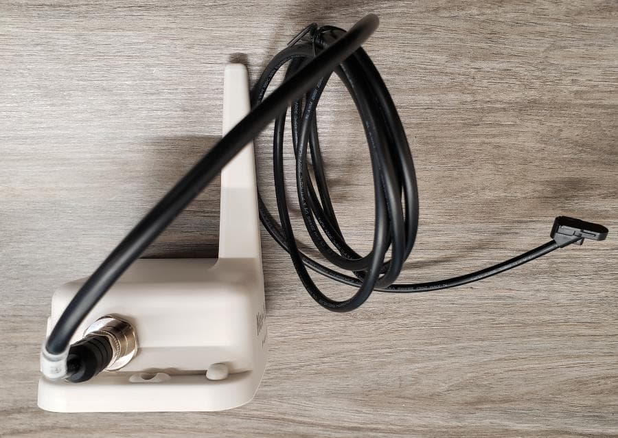
2ADQFMT4AD16W1
Feb 22, 2021Remote Telemetry Communication Unit
Equipment Class
DTS - Digital Transmission System