2ADQOMDA1L11-32.4G Wi-Fi Communication Module
GD Midea Air-conditioning Equipment Co.,Ltd.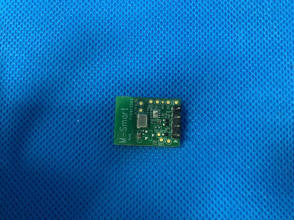
Click to zoom
Application Details
- Equipment Class
- DTS - Digital Transmission System
- Date of Grant
- Jan 18, 2021
- Application Purpose
- Original Equipment
- Date of Application
- Jan 14, 2021
- Equipment Note
- 2.4G Wi-Fi Communication Module
- Frequency Range
- 2412.00000000 - 2462.00000000
- Country
- China
Documents & Files
Document Text
Text extracted from the exhibit documents filed with the FCC. Open a document above to read the original.
Users Manual
MDA1L11-3 Wi-Fi module Operation manual versions Date Content Author 1.0 2019-09-02 initial release 目录 1. Introduction ............................................................................................................................... 3 1.1 Top view ........................................................................................................................... 4 1.2 Module System Block Diagram .................................................................................. 4 1.3 Module technical specifications ............................................................................... 5 2. Structure specification ........................................................................................................... 7 2.1 Module structure size .................................................................................................... 7 2.2 Hardware interface definition .................................................................................... 7 3. Wireless Specification ............................................................................................................. 8 4. Label printing requirements ................................................................................................ 12 1. Introduction MDA1L11-3 Wireless WIFI module is a low-power WIFI module for the Internet of Things. It supports IEEE802.11b / g / n protocol. It also embeds IPV4 / IPV6 TCP / IP, HTTP, DNS, FTP and other complete network protocols, making the terminal more reliable, convenient and easy to use. The MDA1L11-3 module contains HolaConW01 single-chip solution. the chip in software and hardware are used in low-power technology, the purpose is to lower the power consumption of the entire board, the product more competitive. At present, the module provides a complete serial interface functions and equipment to communicate, so you can through the serial port and mobile client to connect the cloud and equipment. ⚫ IEEE 802.1b/g/n, 2.4Ghz ,1T1R ⚫ internal antennas ⚫ Green TX Low power saving technology ⚫ Low power monitor mode ⚫ The maximum operationg frequency of the MCU is 160MHz ⚫ Support "ali cloud", optionally support "midea cloud" ⚫ Full encryption support:WPS, WPA, WPA2 ⚫ Support IPV4, TCP/IP protocol ⚫ Support HTTP, DNS, FTP and other network protocols 1.1 Top view Positive figure On the back of the figure 1.2 Module System Block Diagram As shown in Figure 1, the MDA1L11-3 module contains HolaConW01 single-chip solution. The module uses the internal antenna design in PCB, both for customers to reduce the cost of the antenna, but also eliminates the need to consider the antenna assembly space. figure 1. Module System Block Diagram 1.3 Module technical specifications Main chip HolaConW01 Working frequency 2.412~2.462GHz WIFI standards supportde 802.11b/g/n(1x1) Modulation 11b: DBPSK, DQPSK, CCK, DSSS 11g: BPSK, QPSK, 16QAM, OFDM 11n: MCS0~MSC7 OFDM Supported rates 11b: 1, 2, 5.5 和11Mbps 11g: 6,9,12,18,24,36,48,54Mbps 11n: MCS0~7 communication interface UART0 and UART1 PCB layer structure 4 Layers PCB size 20.0mm(L)x15.0mm(W)x1.0mm(H) Antenna internal antennas, 2.4GHz gain value 2dBi Working temperature -20°C~+75°C Storage temperature -40°C~+75°C Hardware version MDA1L11-3_20*15_1L Ver:1.1 Note/FCC warning: This equipment has been tested and found to comply with the limits for a Class B digital device, pursuant to part 15 of the FCC Rules. These limits are designed to provide reasonable protection against harmful interference in a residential installation. This equipment generates, uses and can radiate radio frequency energy and, if not installed and used in accordance with the instructions, may cause harmful interference to radio communications. However, there is no guarantee that interference will not occur in a particular installation. If this equipment does cause harmful interference to radio or television reception, which can be determined by turning the equipment off and on, the user is encouraged to try to correct the interference by one or more of the following measures: —Reorient or relocate the receiving antenna. —Increase the separation between the equipment and receiver. —Connect the equipment into an outlet on a circuit different from that to which the receiver is connected. —Consult the dealer or an experienced radio/TV technician for help. —This equipment should be installed and operated with a minimum distance of 20cm between the radiator and your body. 2. Structure specification 2.1 Module structure size The size of the module as shown above,length:20.0mm, width:15.0mm, thickness 1.0mm (error +/- 0.1mm) 2.2 Hardware interface definition PIN Signal Name Description 1 VCC Supply Input Pin 2 RXD UART receive data 3 TXD UART transmit data 4 GND Ground 3. Wireless Specification Table1: 802.11b mode Item Spec Specification IEEE802.11b Mode DSSS / CCK Channel CH1 to CH11 Data rate 1, 2, 5.5, 11Mbps TX Characteristics Min. Typ. Max. Unit Remark 1. Power Levels(Calibrated) 1) 18dBm Target 16 18 20 dBm 2. Spectrum Mask @ target power 1) fc +/-11MHz to +/-22MHz - - -30 dBr 2) fc > +/-22MHz - - -50 dBr 3. Frequency Error -10 0 +10 ppm RX Characteristics Min. Typ. Max. Unit 4 Minimum Input Level Sensitivity 1) 1Mbps (FER≦8%) - -93 -98 dBm 2) 2Mbps (FER≦8%) - -92 -95 dBm 3) 5.5Mbps (FER≦8%) - -90 -93 dBm 4) 11Mbps (FER≦8%) - -88 -90 dBm 5 Maximum Input Level (FER≦8%) 0 0.5 dBm Table2: 802.11g mode Item Spec Specification IEEE802.11g Mode OFDM Channel CH1 to CH11 Data rate 6, 9, 12, 18, 24, 36, 48, 54Mbps TX Characteristics Min. Typ. Max. Unit 1. Power Levels 1) 17dBm Target @6Mbps 15 17 19 dBm 2) 15dBm Target @54Mbps 13 15 17 dBm 2. Spectrum Mask @ target power 1) at fc +/- 11MHz - - -20 dBr 2) at fc +/- 20MHz - - -28 dBr 3) at fc > +/-30MHz - - -40 dBr 3 Constellation Error(EVM)@ target power 1) 6Mbps - -22 -25 dB 2) 9Mbps - -23 -25 dB 3) 12Mbps - -24 -26 dB 4) 18Mbps - -24 -27 dB 5) 24Mbps - -25 -27 dB 6) 36Mbps - -25 -30 dB 7) 48Mb…
Text truncated - open the document above for the full version.
Cover Letter(s)
GD Midea Air-Conditioning Equipment Co., Ltd. Date (04/01/2021) TUV SUD BABT TCB Octagon House, Segensworth Road, Fareham, Hampshire, PO15 5RL Confidentiality Request FCC ID: 2ADQOMDA1L11-3 Pursuant to Sections 0.457(d)(1)(ii) and 0.459 of the Commission’s Rules, GD Midea Air-Conditioning Equipment Co., Ltd. hereby requests permanent confidential treatment of information accompanying this application as outlined below: Schematics Bill of Materials/Parts List Block Diagrams GD Midea Air-Conditioning Equipment Co., Ltd. also hereby requests short-term confidential treatment of information accompanying this application as outlined below for a period of 180 days: Internal Photos External Photos User Manual Test Set-up Photographs Theory of Operation The above materials contain trade secrets and proprietary information not customarily released to the public. The public disclosure of these matters might be harmful to the Applicant and provide unjustified benefits to its competitors. The Applicant understands that pursuant to Rule 0.457(d)(1)(ii), disclosure of this Application and all accompanying materials will not be made before the date of the Grant for this Application. Yours sincerely, Company Officer: GD Midea Air-Conditioning Equipment Co., Ltd. Telephone Number: 0757-26339413 Email: [email protected]
Cover Letter(s)
GD Midea Air-Conditioning Equipment Co., Ltd. Date (04/01/2021) TUV SUD BABT TCB Octagon House, Segensworth Road, Fareham, Hampshire, PO15 5RL Dear Sir/Madam, RE: Modular Approval Request for Model: FCC ID: 2ADQOMDA1L11-3 The following attestation addresses the requirements to support modular approval: Modular approval requirement Yes No * (a) The radio elements must have the radio frequency circuitry shielded. Physical components and tuning capacitor(s) may be located external to the shield, but must be on the module assembly √ (b) The module must have buffered modulation/data inputs to ensure that the device will comply with Part 15 requirements with any type of input signal √ (c) The module must contain power supply regulation on the module √ (d) The module must contain a permanently attached antenna, or contain a unique antenna connector, and be marketed and operated only with specific antenna(s), per Sections 15.203, 15.204(b), 15.204(c), 15.212(a), 2.929(b) √ (e) The module must demonstrate compliance in a stand-alone configuration √ (f) The module must be labelled with its permanently affixed FCC ID label, or use an electronic display (See KDB Publication 784748 about labelling requirements) √ (g) The module must comply with all specific rules applicable to the transmitter. The grantee must provide comprehensive instructions to √ GD Midea Air-Conditioning Equipment Co., Ltd. explain compliance requirements (h) The module must comply with RF exposure requirements √ Yours sincerely, Company Officer: GD Midea Air-Conditioning Equipment Co., Ltd. Telephone Number: 0757-26339413 Email: [email protected]
External Photos
External photo
ID Label/Location Info
Label
Internal Photos
External photos
Operational Description
MDA1L11-3 Wi-Fi module Operation manual versions Date Content Author 1.0 2019-09-02 initial release 目录 1. Introduction ............................................................................................................................... 3 1.1 Top view ........................................................................................................................... 4 1.2 Module System Block Diagram .................................................................................. 4 1.3 Module technical specifications ............................................................................... 5 2. Structure specification ........................................................................................................... 7 2.1 Module structure size .................................................................................................... 7 2.2 Hardware interface definition .................................................................................... 7 3. Wireless Specification ............................................................................................................. 8 4. Label printing requirements ................................................................................................ 12 1. Introduction MDA1L11-3 Wireless WIFI module is a low-power WIFI module for the Internet of Things. It supports IEEE802.11b / g / n protocol. It also embeds IPV4 / IPV6 TCP / IP, HTTP, DNS, FTP and other complete network protocols, making the terminal more reliable, convenient and easy to use. The MDA1L11-3 module contains HolaConW01 single-chip solution. the chip in software and hardware are used in low-power technology, the purpose is to lower the power consumption of the entire board, the product more competitive. At present, the module provides a complete serial interface functions and equipment to communicate, so you can through the serial port and mobile client to connect the cloud and equipment. ⚫ IEEE 802.1b/g/n, 2.4Ghz ,1T1R ⚫ internal antennas ⚫ Green TX Low power saving technology ⚫ Low power monitor mode ⚫ The maximum operationg frequency of the MCU is 160MHz ⚫ Support "ali cloud", optionally support "midea cloud" ⚫ Full encryption support:WPS, WPA, WPA2 ⚫ Support IPV4, TCP/IP protocol ⚫ Support HTTP, DNS, FTP and other network protocols 1.1 Top view Positive figure On the back of the figure 1.2 Module System Block Diagram As shown in Figure 1, the MDA1L11-3 module contains HolaConW01 single-chip solution. The module uses the internal antenna design in PCB, both for customers to reduce the cost of the antenna, but also eliminates the need to consider the antenna assembly space. figure 1. Module System Block Diagram 1.3 Module technical specifications Main chip HolaConW01 Working frequency 2.412~2.462GHz WIFI standards supportde 802.11b/g/n(1x1) Modulation 11b: DBPSK, DQPSK, CCK, DSSS 11g: BPSK, QPSK, 16QAM, OFDM 11n: MCS0~MSC7 OFDM Supported rates 11b: 1, 2, 5.5 和11Mbps 11g: 6,9,12,18,24,36,48,54Mbps 11n: MCS0~7 communication interface UART0 and UART1 PCB layer structure 4 Layers PCB size 20.0mm(L)x15.0mm(W)x1.0mm(H) Antenna internal antennas, 2.4GHz gain value 2dBi Working temperature -20°C~+75°C Storage temperature -40°C~+75°C Hardware version MDA1L11-3_20*15_1L Ver:1.1 Note/FCC warning: This equipment has been tested and found to comply with the limits for a Class B digital device, pursuant to part 15 of the FCC Rules. These limits are designed to provide reasonable protection against harmful interference in a residential installation. This equipment generates, uses and can radiate radio frequency energy and, if not installed and used in accordance with the instructions, may cause harmful interference to radio communications. However, there is no guarantee that interference will not occur in a particular installation. If this equipment does cause harmful interference to radio or television reception, which can be determined by turning the equipment off and on, the user is encouraged to try to correct the interference by one or more of the following measures: —Reorient or relocate the receiving antenna. —Increase the separation between the equipment and receiver. —Connect the equipment into an outlet on a circuit different from that to which the receiver is connected. —Consult the dealer or an experienced radio/TV technician for help. —This equipment should be installed and operated with a minimum distance of 20cm between the radiator and your body. 2. Structure specification 2.1 Module structure size The size of the module as shown above,length:20.0mm, width:15.0mm, thickness 1.0mm (error +/- 0.1mm) 2.2 Hardware interface definition PIN Signal Name Description 1 VCC Supply Input Pin 2 RXD UART receive data 3 TXD UART transmit data 4 GND Ground 3. Wireless Specification Table1: 802.11b mode Item Spec Specification IEEE802.11b Mode DSSS / CCK Channel CH1 to CH11 Data rate 1, 2, 5.5, 11Mbps TX Characteristics Min. Typ. Max. Unit Remark 1. Power Levels(Calibrated) 1) 18dBm Target 16 18 20 dBm 2. Spectrum Mask @ target power 1) fc +/-11MHz to +/-22MHz - - -30 dBr 2) fc > +/-22MHz - - -50 dBr 3. Frequency Error -10 0 +10 ppm RX Characteristics Min. Typ. Max. Unit 4 Minimum Input Level Sensitivity 1) 1Mbps (FER≦8%) - -93 -98 dBm 2) 2Mbps (FER≦8%) - -92 -95 dBm 3) 5.5Mbps (FER≦8%) - -90 -93 dBm 4) 11Mbps (FER≦8%) - -88 -90 dBm 5 Maximum Input Level (FER≦8%) 0 0.5 dBm Table2: 802.11g mode Item Spec Specification IEEE802.11g Mode OFDM Channel CH1 to CH11 Data rate 6, 9, 12, 18, 24, 36, 48, 54Mbps TX Characteristics Min. Typ. Max. Unit 1. Power Levels 1) 17dBm Target @6Mbps 15 17 19 dBm 2) 15dBm Target @54Mbps 13 15 17 dBm 2. Spectrum Mask @ target power 1) at fc +/- 11MHz - - -20 dBr 2) at fc +/- 20MHz - - -28 dBr 3) at fc > +/-30MHz - - -40 dBr 3 Constellation Error(EVM)@ target power 1) 6Mbps - -22 -25 dB 2) 9Mbps - -23 -25 dB 3) 12Mbps - -24 -26 dB 4) 18Mbps - -24 -27 dB 5) 24Mbps - -25 -27 dB 6) 36Mbps - -25 -30 dB 7) 48Mb…
Text truncated - open the document above for the full version.
RF Exposure Info
EMC_SZ_FR_39.00 FCC Release 2014-03-20 TÜV SÜD Certification and Testing (China) Co., Ltd. Shenzhen Branch Building 12&13, Zhiheng Wisdomland Business Park, Nantou Checkpoint Road 2, Nanshan District, Shenzhen City, 518052, P. R. China Tel. +86 755 8828 6998, Fax: +86 755 8828 5299 Page 1 of 2 MPE Calculation Product: 2.4G Wi-Fi Communication Module Model no.: MDA1L11-3 Brand name: Midea FCC ID: 2ADQOMDA1L11-3 Rating: DC 5V, 0.5A RF Transmission Frequency: 2412-2462MHz No. of Operated Channel: 11 Modulation: DSSS, OFDM Antenna Type: Internal Antenna Antenna Gain: 2 dBi Description of the EUT: EUT is a 2.4G Wi-Fi Communication Module with WIFI function which operated at 2.4GHz. According to subpart 15.247(i)and subpart §1.1307(b)(1), systems operating under the provisions of this section shall be operated in a manner that ensures that the public is not exposed to radio frequency energy level in excess of the Commission’s guidelines. Limits for Maximum Permissible Exposure (MPE) (§1.1310, §2.1091) (B) Limits for General Population/Uncontrolled Exposure Frequency Range (MHz) Electric Field Strength (V/m) Magnetic Field Strength (A/m) Power Density (mW/cm2) Averaging Time (minutes) 0.3–1.34 614 1.63 *(100) 30 1.34–30 824/f 2.19/f *(180/f²) 30 30–300 27.5 0.073 0.2 30 300–1,500 / / f/1500 30 1,500–100,000 / / 1.0 30 f = frequency in MHz; * = Plane-wave equivalent power density; According to §1.1310 and §2.1091 RF exposure is calculated. Calculated Formulary: Predication of MPE limit at a given distance S = PG/4R² = power density (in appropriate units, e.g. mW/cm2); P = power input to the antenna (in appropriate units, e.g., mW); G = power gain of the antenna in the direction of interest relative to an isotropic radiator, the power gain factor, is normally numeric gain; R = distance to the center of radiation of the antenna (appropriate units, e.g., cm); EMC_SZ_FR_39.00 FCC Release 2014-03-20 TÜV SÜD Certification and Testing (China) Co., Ltd. Shenzhen Branch Building 12&13, Zhiheng Wisdomland Business Park, Nantou Checkpoint Road 2, Nanshan District, Shenzhen City, 518052, P. R. China Tel. +86 755 8828 6998, Fax: +86 755 8828 5299 Page 2 of 2 Calculated Data: Maximum peak output power at antenna input terminal (dBm): 16.9 Maximum peak output power at antenna input terminal (mW): 48.98 Prediction distance (cm): 20 Antenna Gain, typical (dBi): 2.0 Maximum Antenna Gain (numeric): 1.585 The worst case is power density at predication frequency at 20 cm (mW/cm2): 0.015 MPE limit for general population exposure at prediction frequency (mW/cm2): 1.0 0.015 (mW/cm2) < 1 (mW/cm2) Result: Compliant TUV SUD China, Shenzhen Branch Reviewed by: Prepared By: John Zhi/ Project Manager Moon Xiong/Project Engineer Date: 2020-12-30 Date: 2020-12-30
Test Report
Report Number: 68.950.20.0773.01 EMC_SZ_FR_23.03 FCC Release 2017-06-20 TÜV SÜD Certification and Testing (China) Co., Ltd. Shenzhen Branch Building 12&13, Zhiheng Wisdomland Business Park, Nantou Checkpoint Road 2, Nanshan District, Shenzhen City, 518052, P. R. China Tel. +86 755 8828 6998, Fax: +86 755 8828 5299 Page 1 of 56 FCC - TEST REPORT Report Number : 68.950.20.0773.01 Date of Issue: December 08, 2020 Model : MDA1L11-3 Product Type : 2.4G Wi-Fi Communication Module Applicant : GD Midea Air-Conditioning Equipment Co., Ltd. Address : Lingang Road, Beijiao, Shunde 528311 Foshan, Guangdong PEOPLE’S REPUBLIC OF CHINA Manufacturer : GD Midea Air-Conditioning Equipment Co., Ltd. Address : Lingang Road, Beijiao, Shunde 528311 Foshan, Guangdong PEOPLE’S REPUBLIC OF CHINA Test Result : ◼ Positive Negative Total pages including Appendices : 56 TÜV SÜD Certification and Testing (China) Co., Ltd. Shenzhen Branch is a subcontractor to TÜV SÜD Product Service GmbH according to the principles outlined in ISO 17025. TÜV SÜD Certification and Testing (China) Co., Ltd. Shenzhen Branch reports apply only to the specific samples tested under stated test conditions. Construction of the actual test samples has been documented. It is the manufacturer's responsibility to assure that additional production units of this model are manufactured with identical electrical and mechanical components. The manufacturer/importer is responsible to the Competent Authorities in Europe for any modifications made to the production units which result in non-compliance to the relevant regulations. TÜV SÜD Certification and Testing (China) Co., Ltd. Shenzhen Branch shall have no liability for any deductions, inferences or generalizations drawn by the client or others from TÜV SÜD Certification and Testing (China) Co., Ltd. Shenzhen Branch issued reports. This report is the confidential property of the client. As a mutual protection to our clients, the public and ourselves, extracts from the test report shall not be reproduced except in full without our written approval Report Number: 68.950.20.0773.01 EMC_SZ_FR_23.03 FCC Release 2017-06-20 TÜV SÜD Certification and Testing (China) Co., Ltd. Shenzhen Branch Building 12&13, Zhiheng Wisdomland Business Park, Nantou Checkpoint Road 2, Nanshan District, Shenzhen City, 518052, P. R. China Tel. +86 755 8828 6998, Fax: +86 755 8828 5299 Page 2 of 56 1 Table of Contents 1 Table of Contents ................................................................................................................................................................... 2 2 Details about the Test Laboratory .......................................................................................................................................... 3 3 Description of the Equipment Under Test ............................................................................................................................. 4 4 Summary of Test Standards ................................................................................................................................................... 5 5 Summary of Test Results ....................................................................................................................................................... 6 6 General Remarks .................................................................................................................................................................... 7 7 Test Setups ............................................................................................................................................................................. 8 8 Technical Requirement .......................................................................................................................................................... 9 8.1 Conducted Emission...................................................................................................................................................... 9 8.2 Conducted peak output power ..................................................................................................................................... 12 8.3 6dB bandwidth ............................................................................................................................................................ 14 8.4 Power spectral density ................................................................................................................................................. 19 8.5 Spurious RF conducted emissions ............................................................................................................................... 23 8.6 Band edge testing ........................................................................................................................................................ 45 8.7 Spurious radiated emissions for transmitter ................................................................................................................ 48 9 Test Equipment List ............................................................................................................................................................. 54 10 System Measurement Uncertainty ....................................................................................................................................... 56 Report Number: 68.950.20.0773.01 EMC_SZ_FR_23.03 FCC Release 2017-06-20 TÜV SÜD Certification and Testing (China) Co., Ltd. Shenzhen Branch Building 12&13, Zhiheng Wisdomland Business Park, Nantou Checkpoint Road 2, Nanshan District, Shenzhen City, 518052, P. R. China Tel. +86 755 8828 6998, Fax: +86 755 8828 5299 Page 3 of 56 2 Details about the Test Laboratory Details about the Test Laboratory Test Site 1 Company name: TÜV SÜD Certification and Testing (China) Co., Ltd. Shenzhen Branch Building 12&13, Zhiheng Wisdomland Business Park, Nantou Checkpoint Road 2,…
Text truncated - open the document above for the full version.
Test Setup Photos
Test setup photo Radiated spurious emission 30MHz-1GHz Radiated spurious emission 1GHz-18GHz Radiated spurious emission 18GHz-40GHz AC Conducted emission test
Contact Information
Applicant
Flora Wu
Test Firm
TUV SUD Cert & Testing (China) Co., Ltd.Harry Zhou
[email protected]86 755 3332 3281
Technical Specifications
| # | Rule Parts | Frequency Range | Power Output |
|---|---|---|---|
| 1 | 15C | 2.41 GHz - 2.46 GHz | 48.98 mW |
Other Applications from GD Midea Air-conditioning Equipment Co.,Ltd.
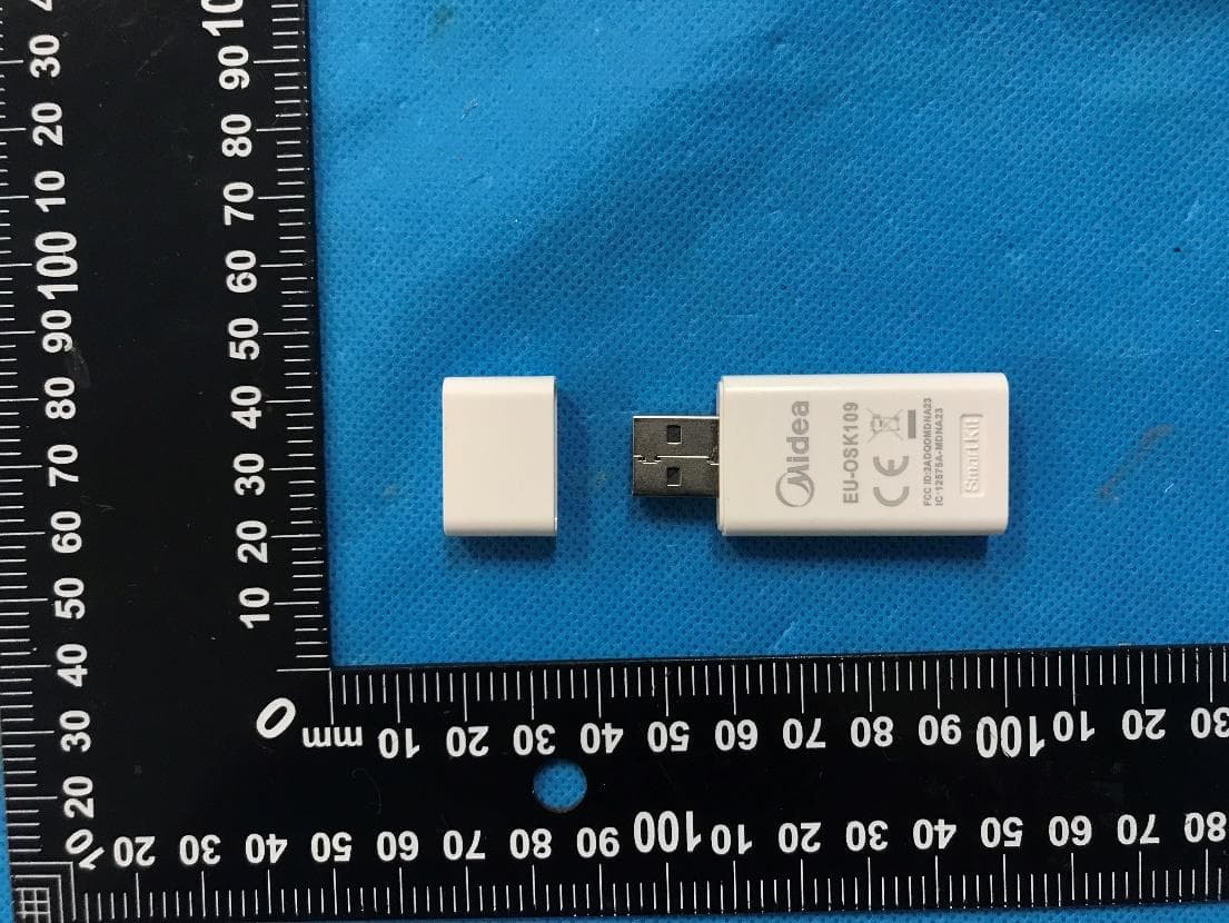
2ADQOMDNA23
Jun 27, 2023Smart Kit with Bluetooth Low Energy and Wi-Fi
Equipment Class
DTS - Digital Transmission System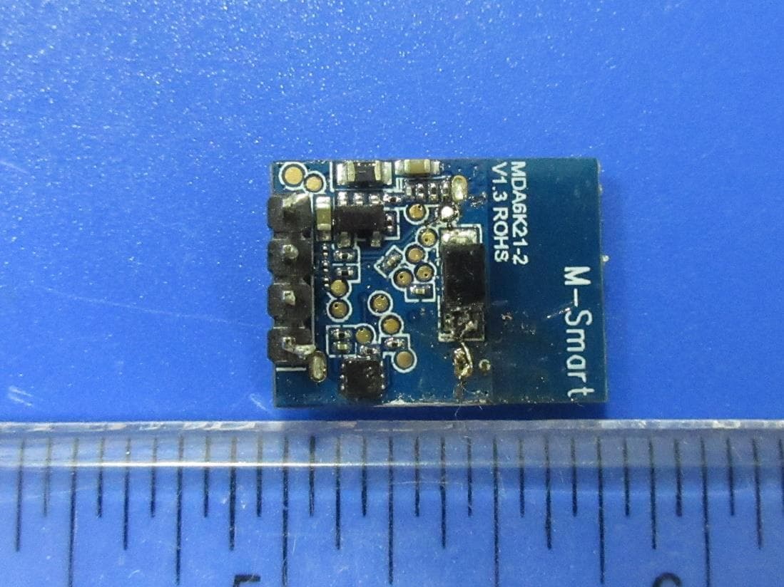
2ADQOMDA6K21-2
Aug 26, 20212.4G Bluetooth Communication Module
Equipment Class
DTS - Digital Transmission System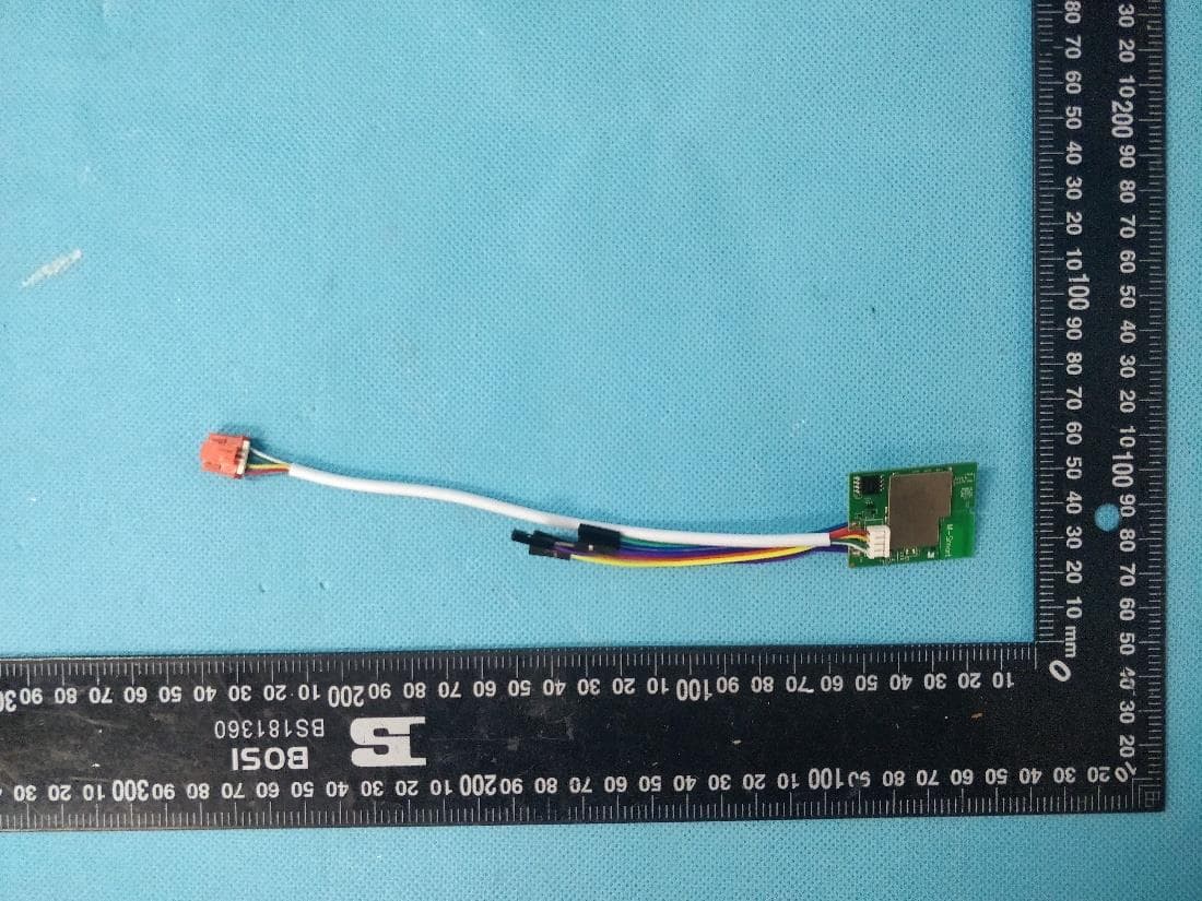
2ADQO3SB3350N3
Jul 12, 2020Bluetooth&Wi-Fi dual band Communication Module
Equipment Class
DTS - Digital Transmission System
2ADQOMDNA15
Nov 09, 2015Smart Kit Wi-Fi Adaptor
Equipment Class
DTS - Digital Transmission System
2ADQOMDNA14
Mar 09, 2015Smart Kit USB Wi-Fi adaptor
Equipment Class
DTS - Digital Transmission System