2ADS4BRO1Bluetooth transmitter that controls luminous objects wirelessly from dMX signals
Eski Inc.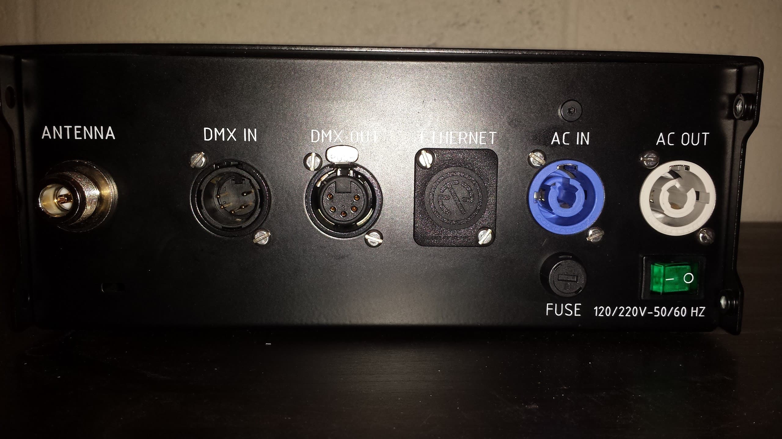
Click to zoom
Application Details
- Equipment Class
- DTS - Digital Transmission System
- Date of Grant
- Dec 14, 2015
- Application Purpose
- Original Equipment
- Date of Application
- Dec 14, 2015
- Equipment Note
- Bluetooth transmitter that controls luminous objects wirelessly from dMX signals
- Frequency Range
- 2402.00000000 - 2480.00000000
- Company
- Eski Inc.
- Country
- Canada
Documents & Files
Document Text
Text extracted from the exhibit documents filed with the FCC. Open a document above to read the original.
Users Manual
Version 1.4 2015-08-25 INSTALLATION MANUAL TABLE OF CONTENTS 1. PixMob Broadcaster 2. Materials needed 3. Installation 4. Broadcaster menu 5. Troubleshooting 6. Broadcaster characteristics p. 4 p. 6 p. 8 p. 10 p. 14 p. 15 1. Color indicator 2. Control buttons 3. Outgoing RF indicator light 4. DMX signal indicator light 5. Ethernet indicator light 6. On / Off indicator light A Broadcaster is a Bluetooth trans- mitter that controls PixMob luminous objects wirelessly. Similarly to a LED flood light it is controllable by a lighting board through DMX. 1. PixMob Broadcaster PixMob Broadcaster 4 1 2 3 4 5 6 6. DMX XLR5 IN 7. DMX XLR5 OUT 8. Ethernet (not activated) 9. Powercon IN (110V - 220V AC) 10. Powercon OUT (110V - 220V AC) 11. Antenna PixMob Broadcaster 5 11106789 1. PixMob Broadcaster 2. Antenna 3. DMX XLR5 cable 4. Power cable (Powercon) With light console 2. Material needed Material needed 6 1 2 1. Plug DMX IN (female) at Broadcaster. 2. Plug DMX OUT (male) at console. 3. Install fixture in console (pc). Connecting the Broadcaster Material needed 7 CONSOLEBROADCASTER DMX Examples for connecting the Broadcaster. 4 3 Installation 8 3. Installation This picture shows the different connections of the Broadcaster. Broadcasters can also be connected in daisy-chain by connecting DMX OUT to DMX IN of the next Broadcaster and AC OUT to AC IN of the next Broadcaster. Installing the Broadcaster
Users Manual
Installation 9 • For electrical reasons, do not connect more than 10 Broadcasters in daisy-chain. • All the Broadcasters on the same line must be connected to one dedicated DMX line in order to respect our frame rate of 15 fps. • We recommend putting a 120 Ohm DMX terminator on the DMX out of the last Broadcaster in the line. • If using antenna cable extenders, use cables with impedance of 50 Ohm only. • Replace fuse with rating of 250V, 4A or 5A only. Broadcaster menu 10 When powering up, the Broadcaster will display the relevant version information. For example here, we have : - Revision 1.6.1 - Release date Broadcaster start screen 4. Broadcaster menu Broadcaster menu 11 On the right side of the control display are four control buttons. Next to the control buttons are four LED status indicators. The LED status indicators blink whenever the Broadcaster has incoming DMX, outgoing RF or Ethernet communication. There is also a LED indicator for power. Note that the blinking speed of the green DMX LED depends on the frame rate of the DMX signal received. For example, when the incoming DMX has a speed of 30 fps, the blinking is fast. If the incoming DMX is at a speed of 15 fps, the blinking is slower. Broadcaster interface Broadcaster menu 12 The speed of incoming DMX is automatically shown on the right side of the control display, whenever the Broadcaster is receiving DMX. To slow down the speed of the DMX, press DOWN to select the “BRO Out” line and then press ENTER. Use UP and DOWN to properly set up the speed of outgoing DMX you need. - The maximum DMX OUT speed is 20 fps. - Once the proper speed is set, press ENTER to save changes. Slowing down DMX speed Note that you can also turn off the outgoing DMX by setting the outgoing fps to zero. Broadcaster menu 13 To set up a DMX address, put the cursor on the “Address” line, press ENTER and set the address using UP and DOWN. Once the proper address is set, press ENTER to save the changes. Setting up DMX address Troubleshooting 14 5. Troubleshooting Once the Broadcaster is properly connected and receiving DMX data in PixMob format, you should see the three (red, green and blue) LED status indicator illuminate at the front of the Broadcaster. 1. Solid red (POWER): Broadcaster is powered ON. 2. Blinking green (DMX): receiving DMX. 3. Solid blue (RF): transmitting PixMob Bluetooth signal. To make sure the Broadcaster is properly sending Bluetooth signals, you can use an application on your phone that is called Bluetooth LE Scanner (available in iOS and Android). When scanning for a Bluetooth signal, the Broadcaster will appear in the list as BRO. Caracteristics 15 6. Caracteristics Input protocol Output protocol Frequency Maximum range Voltage input AC current Working temp Working humidity Protection rating Body dimension Weight Rack mount height DMX PIXMOB 2.4 GHz up to 100 meters 85 - 240 VAC 0.2A / 115 VAC 0.1A / 230 VAC 0 o C to 60 o C 20% to 75% RH non-condensing IP50 22.2 cm x 21 cm x 8.7 cm 3.2 kg 2U Troubleshooting 28 TECHNICAL SUPPORT If you need further support, our professionnal team is always at the other end of the line. Do not hesitate to get in touch! E-mail: [email protected] Telephone: +1·514·510·5777 Troubleshooting 29 103 Rue de Louvain Ouest, Montréal, QC, H2N 1A3, Canada www.pixmob.com T +1 514 510-5777 E [email protected]
Users Manual
TABLE OF CONTENTS 1‐ PixMob BroadcasterPage 2 2‐ FCC StatementsPage 4 3‐ IC StatementsPage 5 4‐ Material neededPage 6 5‐ InstallationPage 7 6‐ Broadcaster menuPage 8 7‐ TroubleshootingPage 10 8‐ Broadcaster characteristicsPage 11 PixMob Broadcaster 1 1.PixMob Broadcaster A Broadcaster is a Bluetooth transmitter that controls PixMob luminous objects wirelessly. Similarly to a LED flood light, it is controllable by a lighting board through DMX. PixMob Broadcaster 2 1.Bluetooth antenna connector (Female “N” type) 2.DMX XLR5 IN 3.DMX XLR5 OUT 4.Ethernet connector (for future use) 5.Powercon IN (110V 220V AC) 6.Powercon OUT (110V 220V AC) PixMob Broadcaster 3 2.FCC Statements FCC ID: 2ADS4BRO1 This device complies with part 15.247 of the FCC Rules. Operation is subject to the following two conditions: (1) This device may not cause harmful interference, and (2) this device must accept any interference received, including interference that may cause undesired operation. Caution: Changes or modifications not expressly approved by the party responsible for compliance could void the user's authority to operate this equipment. Note: This equipment has been tested and found to comply with the limits for a Class B digital device, pursuant to part 15 of the FCC Rules. These limits are designed to provide reasonable protection against harmful interference in a residential installation. This equipment generates, uses and can radiate radio frequency energy and, if not installed and used in accordance with the instructions, may cause harmful interference to radio communications. However, there is no guarantee that interference will not occur in a particular installation. If this equipment does cause harmful interference to radio or television reception, which can be determined by turning the equipment off and on, the user is encouraged to try to correct the interference by one or more of the following measures: —Reorient or relocate the receiving antenna. —Increase the separation between the equipment and receiver. —Consult the dealer or an experienced radio/TV technician for help. PixMob Broadcaster 4 3.IC Statements IC: 7254ABRO1 This device complies with Industry Canada licenceexempt RSS 247 standard. Operation is subject to the following two conditions: (1) this device may not cause interference, and (2) this device must accept any interference, including interference that may cause undesired operation of the device. Cet appareil est conforme avec Industrie Canada exempts de licence standard RSS 247. Son fonctionnement est soumis aux deux conditions suivantes: (1) cet appareil ne doit pas provoquer d'interférences et (2) cet appareil doit accepter toute interférence, y compris celles pouvant causer un mauvais fonctionnement de l'appareil. PixMob Broadcaster 5 4.Material needed 1. Bluetooth antenna (Male “N” type connector) 2. DMX XLR 5pin cable 3. PixMob Broadcaster 4. Broadcaster power cable (Powercon) PixMob Broadcaster 6 5.Installation This picture shows the different connections of the Broadcaster. Broadcasters can also be connected in a daisychain by connecting DMX OUT to DMX IN of the next Broadcaster and AC OUT to AC IN of the next Broadcaster. Note: The equipment will be professionally installed • For electrical reasons, do not connect more than 10 Broadcasters in a daisychain. • All the Broadcasters on the same line must be connected to one dedicated DMX line in order to respect our frame rate of 15 fps. • We recommend putting a 120 Ohm DMX terminator on the DMX out of the last Broadcaster in the line. • If using antenna cable extenders, use cables with impedance of 50 Ohm only. • Replace fuse with rating of 250V, 4A or 5A only. PixMob Broadcaster 7 6.Broadcaster menu a.Home screen When powering up, the Broadcaster will display the relevant version information. For example here, we have: Revision 1.6.1 Release date PixMob Broadcaster 8 b.Broadcaster interface On the right side of the control display are four control buttons. Next to the control buttons are four LED status indicators. The LED status indicators blink whenever the Broadcaster has incoming DMX, outgoing RF or Ethernet communication. There is also a LED indicator for power. Note that the blinking speed of the green DMX LED depends on the frame rate of the DMX signal received. For example, when the incoming DMX has a speed of 30 fps, the blinking is fast. If the incoming DMX is at a speed of 15 fps, the blinking is slower. c.Slowing down DMX speed The speed of incoming DMX is automatically shown on the right side of the control display, whenever the Broadcaster is receiving DMX. To slow down the speed of the DMX, press DOWN to select the “BRO Out” line and then press ENTER. Use UP and DOWN to properly set up the speed of outgoing DMX you need. The maximum DMX OUT speed is 20 fps. Once the proper speed is set, press ENTER to save changes. Note that you can also turn off the outgoing DMX by setting the outgoing fps to zero. PixMob Broadcaster 9 d.Setting up DMX address To set up a DMX address, put the cursor on the “Address” line, press ENTER and set the address using UP and DOWN. Once the proper address is set, press ENTER to save the changes. e.Silence request A silence request is automatically sent when the Broadcaster is transmitting. This request has priority over the Sparks applications for the signal sent to the PixMob wristbands. 7.Troubleshooting Once the Broadcaster is properly connected and receiving DMX data in PixMob format, you should see the three (red, green and blue) LED status indicator illuminate at the front of the Broadcaster. 1. Solid red (POWER): Broadcaster is powered ON. 2. Blinking green (DMX): receiving DMX. 3. Solid blue (RF): transmitting PixMob Bluetooth signal. To make sure the Broadcaster is properly sending Bluetooth signals, you can use an application on your phone that is ca…
Text truncated - open the document above for the full version.
External Photos
01/10/201520150807 16.06.11.jpg https://drive.google.com/a/pixmob.com/file/d/0B3ctb_GSXUcYTZYSk0zc1I2ejQ/view1/1 01/10/201520150807 13.20.02.jpg https://drive.google.com/a/pixmob.com/file/d/0B3ctb_GSXUcWEZ0SUxGZjJoOFU/view1/1
ID Label/Location Info
ID: Model No.: PX-BR01 FCC ID: 2ADS4BRO1 IC : 7254A-BRO1 Rating: 100-240VAC, 2.0A, 50/60Hz Max Current Link: 4A Date de fabrication / Manufacturing date: POUR EMPLACEMENT SEC SEULEMENT FOR DRY LOCATION ONLY ID: Model No.: PX-BR01 FCC ID: 2ADS4BRO1 IC : 7254A-BRO1 Rating: 100-240VAC, 2.0A, 50/60Hz Max Current Link: 4A Date de fabrication / Manufacturing date: POUR EMPLACEMENT SEC SEULEMENT FOR DRY LOCATION ONLY ID: Model No.: PX-BR01 FCC ID: 2ADS4BRO1 IC : 7254A-BRO1 Rating: 100-240VAC, 2.0A, 50/60Hz Max Current Link: 4A Date de fabrication / Manufacturing date: POUR EMPLACEMENT SEC SEULEMENT FOR DRY LOCATION ONLY ID: Model No.: PX-BR01 FCC ID: 2ADS4BRO1 IC : 7254A-BRO1 Rating: 100-240VAC, 2.0A, 50/60Hz Max Current Link: 4A Date de fabrication / Manufacturing date: POUR EMPLACEMENT SEC SEULEMENT FOR DRY LOCATION ONLY ID: Model No.: PX-BR01 FCC ID: 2ADS4BRO1 IC : 7254A-BRO1 Rating: 100-240VAC, 2.0A, 50/60Hz Max Current Link: 4A Date de fabrication / Manufacturing date: POUR EMPLACEMENT SEC SEULEMENT FOR DRY LOCATION ONLY ID: Model No.: PX-BR01 FCC ID: 2ADS4BRO1 IC : 7254A-BRO1 Rating: 100-240VAC, 2.0A, 50/60Hz Max Current Link: 4A Date de fabrication / Manufacturing date: POUR EMPLACEMENT SEC SEULEMENT FOR DRY LOCATION ONLY ID: Model No.: PX-BR01 FCC ID: 2ADS4BRO1 IC : 7254A-BRO1 Rating: 100-240VAC, 2.0A, 50/60Hz Max Current Link: 4A Date de fabrication / Manufacturing date: POUR EMPLACEMENT SEC SEULEMENT FOR DRY LOCATION ONLY ID: Model No.: PX-BR01 FCC ID: 2ADS4BRO1 IC : 7254A-BRO1 Rating: 100-240VAC, 2.0A, 50/60Hz Max Current Link: 4A Date de fabrication / Manufacturing date: POUR EMPLACEMENT SEC SEULEMENT FOR DRY LOCATION ONLY ID: Model No.: PX-BR01 FCC ID: 2ADS4BRO1 IC : 7254A-BRO1 Rating: 100-240VAC, 2.0A, 50/60Hz Max Current Link: 4A Date de fabrication / Manufacturing date: POUR EMPLACEMENT SEC SEULEMENT FOR DRY LOCATION ONLY ID: Model No.: PX-BR01 FCC ID: 2ADS4BRO1 IC : 7254A-BRO1 Rating: 100-240VAC, 2.0A, 50/60Hz Max Current Link: 4A Date de fabrication / Manufacturing date: POUR EMPLACEMENT SEC SEULEMENT FOR DRY LOCATION ONLY
Internal Photos
26/10/201520151026 10.31.38.jpg https://drive.google.com/drive/u/0/folders/0B3ctb_GSXUcfkhpYjJjMExFZDdzTnZrMldCcGtkdERrOWQtT014RmdxUVV6d0dIZDcweEk1/1 26/10/201520151026 10.31.24.jpg https://drive.google.com/drive/u/0/folders/0B3ctb_GSXUcfkhpYjJjMExFZDdzTnZrMldCcGtkdERrOWQtT014RmdxUVV6d0dIZDcweEk1/1 26/10/201520151026 10.29.59.jpg https://drive.google.com/drive/u/0/folders/0B3ctb_GSXUcfkhpYjJjMExFZDdzTnZrMldCcGtkdERrOWQtT014RmdxUVV6d0dIZDcweEk1/1
Internal Photos
26/10/201520151026 10.29.43.jpg https://drive.google.com/drive/u/0/folders/0B3ctb_GSXUcfkhpYjJjMExFZDdzTnZrMldCcGtkdERrOWQtT014RmdxUVV6d0dIZDcweEk1/1 26/10/201520151026 10.31.07.jpg https://drive.google.com/drive/u/0/folders/0B3ctb_GSXUcfkhpYjJjMExFZDdzTnZrMldCcGtkdERrOWQtT014RmdxUVV6d0dIZDcweEk1/1 26/10/201520151026 10.30.55.jpg https://drive.google.com/drive/u/0/folders/0B3ctb_GSXUcfkhpYjJjMExFZDdzTnZrMldCcGtkdERrOWQtT014RmdxUVV6d0dIZDcweEk1/1
RF Exposure Info
Prediction of MPE limit at a given distance Equation from page 18 of OET Bulletin 65, Edition 97-01 where:S = power density P = power input to the antenna G = power gain of the antenna in the direction of interest relative to an isotropic radiator R = distance to the center of radiation of the antenna Maximum peak output power at device output terminal:12.99dBm Cable and Jumper loss:0.0dB Maximum peak output power at antenna input terminal:12.99dBm 19.90673339mW Single Antenna gain (typical):4.9dBi Number of Antennae:1 Total Antenna gain (typical):4.9dBi 3.090295433(numeric) Prediction distance:20cm Prediction frequency:2402MHz MPE limit for uncontrolled exposure at prediction frequency:1mW/cm 2 Power density at prediction frequency:0.012239 mW/cm 2 0.122386W/m 2 Tx On time:1.000000ms Tx period time:1.000000ms Average Factor:100.000000% Average Power density at prediction frequency:0.122386W/m 2 Maximum allowable antenna gain:24.02269855dBi Margin of Compliance:19.12269855 dB 2 4R PG S
Test Report
www.nemko.com Nemko Canada Inc., a testing laboratory, is accredited by the Standards Council of Canada. The tests included in this report are within the scope of this accreditation FCC 15.247 and RSS-247.docx; Date: May 2015 SCC Accredited LAB LAB Accrédité CCN TM ONE WORLDOURAPPROVAL Test report 292630-1R2TRFWL Date of issue: December 10, 2015 Applicant: ESKI Inc. Product: Broadcaster Model: PX-BR01 FCC ID: IC Registration number: 2ADS4BRO1 7254A-BRO1 Specifications: FCC 47 CFR Part 15 Subpart C, §15.247 Operation in the 902–928 MHz, 2400–2483.5 MHz, 5725–5850 MHz RSS-247, Issue 1, May 2015, Section 5 Digital Transmission Systems (DTSs), Frequency Hopping Systems (FHSs) and Licence-Exempt Local Area Network (LE-LAN) Devices Report reference ID: 292630-1R2TRFWL Page 2 of 34 Test location Company name Nemko Canada Inc. Address 303 River Road City Ottawa Province Ontario Postal code K1V 1H2 Country Canada Telephone +1 613 737 9680 Facsimile +1 613 737 9691 Toll free +1 800 563 6336 Website www.nemko.com Site number FCC: 176392; IC: 2040A-4 (3 m semi anechoic chamber) Tested by Avul Nzenza, EMC Specialist Reviewed by Andrey Adelberg, Senior Wireless/EMC Specialist Review date December 10, 2015 Reviewer signature Limits of responsibility Note that the results contained in this report relate only to the items tested and were obtained in the period between the date of initial receipt of samples and the date of issue of the report. This test report has been completed in accordance with the requirements of ISO/IEC 17025. All results contain in this report are within Nemko Canada’s ISO/IEC 17025 accreditation. Copyright notification Nemko Canada Inc. authorizes the applicant to reproduce this report provided it is reproduced in its entirety and for use by the company’s employees only. Any use which a third party makes of this report, or any reliance on or decisions to be made based on it, are the responsibility of such third parties. Nemko Canada Inc. accepts no responsibility for damages, if any, suffered by any third party as a result of decisions made or actions based on this report. © Nemko Canada Inc. Report reference ID: 292630-1R2TRFWL Page 3 of 34 Table of contents Table of contents .......................................................................................................................................................................................................... 3 Section 1. Report summary ................................................................................................................................................................................. 4 1.1 Applicant and manufacturer .................................................................................................................................................................................... 4 1.2 Test specifications .................................................................................................................................................................................................... 4 1.3 Test methods ............................................................................................................................................................................................................ 4 1.4 Statement of compliance ......................................................................................................................................................................................... 4 1.5 Exclusions ................................................................................................................................................................................................................. 4 1.6 Test report revision history ...................................................................................................................................................................................... 4 Section 2. Summary of test results ....................................................................................................................................................................... 5 2.1 FCC Part 15 Subpart C, general requirements test results ........................................................................................................................................ 5 2.2 FCC Part 15 Subpart C, intentional radiators test results.......................................................................................................................................... 5 2.3 IC RSS-GEN, Issue 4, test results ............................................................................................................................................................................... 5 2.4 IC RSS-247, Issue 1, test results ................................................................................................................................................................................ 6 Section 3. Equipment under test (EUT) details ..................................................................................................................................................... 7 3.1 Sample information .................................................................................................................................................................................................. 7 3.2 EUT information ....................................................................................................................................................................................................... 7 3.3 Technical information .............................................................................................................................................................................................. 7 3.4 Product description and theory of operation ..............................................................................................…
Text truncated - open the document above for the full version.
Test Setup Photos
www.nemko.com Nemko Canada Inc., a testing laboratory, is accredited by the Standards Council of Canada. The tests included in this report are within the scope of this accreditation setup photos.docx; Date: May 2013 SCC Accredited LAB LAB Accrédité CCN TM ONE WORLDOURAPPROVAL Setup photos 291630-1RADWL Date of issue: 9T Applicant: ESKI Inc. Product: Broadcaster Model: PX-BR01 FCC ID: IC Registration number: 2ADS4BLE 7254A-BLE Section 1: setup photos Report reference ID: -292630-1RADWL Page 2 of 3 Section 1. Setup photos 1.1 Radiated Front view Section 1: setup photos Report reference ID: -292630-1RADWL Page 3 of 3 1.2 Radiated back view
Contact Information
Applicant
GACEMI Merwan(Hardware development Team Lead)
Test Firm
Nemko Canada Inc. (Ottawa)Charles Neal
Technical Specifications
| # | Rule Parts | Frequency Range | Power Output |
|---|---|---|---|
| 1 | 15C | 2.40 GHz - 2.48 GHz | 20.00 mW |
Other Applications from Eski Inc.
2ADS4-LUXXPLUS
Apr 16, 2024NOVA Plus LUXX Plus
Equipment Class
UWB - Ultra Wideband Transmitter
2ADS4-WAVENODE
Oct 20, 2022WaveNode (Node RF)
Equipment Class
DTS - Digital Transmission System
2ADS4101-00070
Apr 13, 2021Clip 3
Equipment Class
DTS - Digital Transmission System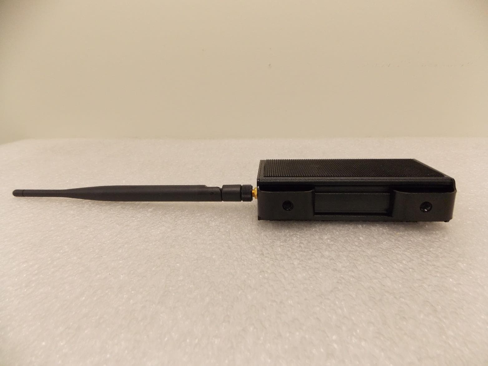
2ADS4HUB2
Feb 02, 2020BLUETOOTH TRANSMITTER / RECEIVER
Equipment Class
DTS - Digital Transmission System