2ADXI-SBHD20TRIM II PRO
SkyBell Technologies Inc.
Click to zoom
Application Details
- Equipment Class
- NII - Unlicensed National Information Infrastructure TX
- Date of Grant
- Nov 10, 2020
- Application Purpose
- Original Equipment
- Date of Application
- Nov 10, 2020
- Equipment Note
- TRIM II PRO
- Frequency Range
- 5745.00000000 - 5825.00000000
- Company
- SkyBell Technologies Inc.
- Country
- United States
Documents & Files
Document Text
Text extracted from the exhibit documents filed with the FCC. Open a document above to read the original.
Users Manual
TRIM2 S TRIM2 B Trim II Pro Doorbell Camera HD video. Two-Way Audio. TRIM II PRO Doorbell Camera On-demand video View your front door at anytime Record video Save videos to your Alarm.com account Motion sensor Know if someone is at or near the door Two-Way Audio Hear and speak to visitors remotely Requirements Power: 10-30VAC, 50/60Hz,0.5A Max or12VDC,0.5 to1.0A wired to in- home mechanical chime - digital doorbell chime compatibility requires SkyBell Digital Doorbell Adapter - not included Wi-Fi: 802.11 b/g/n/ac, 2.4 and 5 GHz Upload bandwidth: 2 Mbps required Mounting: Mounting plate affixes to flat surface and utilizes existing doorbell wiring Mobile device: Alarm.com app compatible with Apple iOS, Android Specifications Video camera: 1080p resolution, 180° view Night vision: IR up to 16 feet (5 m) Audio: Built-in speaker and microphone Motion sensor: PIR detects motion up to 10 feet Dimensions: 1.4 in/3.7 cm wide; 4.8 in/12.2 cm tall 1.1 in/2.9 cm deep, 3.1 oz/87.9 g weight Environment: operating temp -40°F/-40°C to 113°F/45°C Exclusively for systems powered by Alarm.com *Alarm.com app required. Not compatible with the Sky Bell app. Sleek design Install on thin door trims and frames Answer your door from anywhere. With the Alarm.com mobile app you get activity alerts and recorded clips so you can see whofs at your door, day and night. The built-in Two-Way Audio lets you hear and speak to visitors. When paired with other Alarm.com smart home products, you can even unlock the door or turn on lights for visitors - all right from the app. Need help? Go to alarm.com/doorbell Use Alarm.com Doorbell Camera Hardware Alarm.com’s Doorbell Camera hardware must be used: • Alarm.com G e n 5 C h i m e Camera • Alarm.com T r i m I I P r o Doorbell Camera SkyBell HD consumer hardware is not supported. Slim Line Doorbell Camera hardware is not supported on the SkyBell platform or other service provider platforms. Remove Existing Doorbell Button Take care to prevent the existing doorbell wires from slipping into the wall. Attach the Doorbell Mounting Bracket to the Wall Feed the existing doorbell wires through the hole in the center of the bracket. Affix the bracket firmly to the wall by driving the provided wall screws through the top and bottom holes in the bracket. Failure to make the bracket flush on the wall could cause a poor power connection between the bracket and the doorbell camera. Connect Power Wires to the Mounting Bracket Loosen the terminal screws and insert the wires beneath the screws. Do not short (touch together) the wires during this process. Tighten the screws. The wires must be of approximately equal thickness, and the screws should be tightened approximately the same amount so that the screwheads are flush. If the wires are thick, splice short lengths of additional thinner wire. The splice joints can be hidden inside the wall, and the thinner wire can be used to connect to the mounting bracket. Attach the Doorbell Camera to the Mounting Bracket Slide the top of the doorbell camera down on to the mounting bracket and push the front of the doorbell camera toward the wall. Tighten the set screw located on the bottom of the camera, being careful not to damage it (power tools should not be used with the set screw). The camera’s LED should begin to illuminate. LED COLORS, BUTTON FUNCTIONS AND GENERAL TROUBLESHOOTING Battery Charging If the LED is alternating between Red and Blue (HD Edition) or pulsing Blue(Slim Line), the doorbell camera’s battery is charging. The duration of the presyncing charge process varies due to differences in existing doorbell circuits but normally takes less than 30 minutes. See the Power Information and Troubleshooting section if this state persists. If the LED is flashing Orange, the doorbell needs to be manually placed into AP mode. Press and hold the Main Button until the LED begins rapidly flashing green, then release. The LED will flash green as the Doorbell Camera scans the Wi-Fi networks in the area. The Doorbell Camera should enter AP Mode after a couple of minutes and the LED should begin alternating Red and Green. Enter AP Mode (Broadcast Syncing Mode) Press and HOLD the Main Button until the LED begins a GREEN rapid strobe flash, then release the button. When the LED flashes Green, it means the Alarm.com Wi-Fi Doorbell Camera is in the process of entering AP Mode. The LED will alternate Red and Green when the device has entered AP Mode. Power Cycle Press and HOLD the Main Button until the LED begins a Blue rapid strobe flash. The power cycle could take up to 2 minutes. Note: You can power cycle the Alarm.com T r i m I I P r o Doorbell Camera when it is in AP Mode (see instructions above). Press and HOLD the button until the LED flashes Blue. Factory Reset Caution: If you initiate a Factory Reset, the Doorbell Camera will need to be re-connected to Wi-Fi and resynced with the account. Press and HOLD the button until the LED begins a Yellow rapid strobe flash. The reset could take up to 2 minutes. Wi-Fi Connectivity Online Resources Visit alarm.com/doorbell for troubleshooting tips, installation videos and more CAN ICES-3 (B)/NMB-3(B) Notes: The Alarm.com T r i m I I P r o Doorbell Camera will flash Blue before it flashes Yellow – do not release during the flashing Blue phase (this will power cycle the device). You can factory reset the device when it is in AP Mode (see instructions above). Press and HOLD the Main Button until the LED flashes Yellow. If a factory reset is performed on a camera that is already connected to Wi-Fi, the camera will need to be re-installed to re-establish its Wi-Fi connection. Warning: This device complies with part 15 of the FCC Rules. Operation is subject to the following two conditions: (1) This device may not cause harmful interference, and (2) this device must accept any interference received, including interference that may cause undesired operation. FCC warning: Changes or modifications to this unit not expressly…
Text truncated - open the document above for the full version.
Cover Letter(s)
SKY巳ELL: TECHNOLOGIES, INC 18 June 2020 Federal Communications Commission 445 12 th Street SW Washington, DC 20554 Subject: Limited Agency Agreement SKYBELL TECHNOLOGIES INC FCC ID: 2ADXI-SBHD20 To Whom It May Concern: W e , S K Y B E L L T E C H N O L O G I E S I N C . , h e r e b y a u t h o r i z e d lnte1iek T e s t i n g S e r v i c e s t o a c t a s o u r A g e n t fo r t h e p u r p o s e o f p r e p a r i n g a p p l i c a t i o n fo r F C C I D n u m b e r 2ADXI-SBHD20 u n d e r a l l applicable parts of the FCC rules and regulations. T h e e ff e c t i v e d a t e o f t h i s l i m i t e d a g e n c y a g r e e m e n t i s ( 1 8 - J u n - 2 0 2 0 ) . T h e L i m i t e d A g e n c y A g r e e m e n t e x p i r e s o n ( 3 0 - D e c - 2 0 2 0 ) , u n l e s s s o o n e r t e n n i n a t e d o r e x t e n d e d b y w r i t t e n n o t i c e t o I n t e 1 t e k Testing Services and the Federal Communications Commission. This is to advise that we are in full compliance with the Anti-Drug Abuse Act. The applicant is not subject to a denial of federal benefits pursuant to Section 5301 of the Anti-Drug Act of 1988, 21 U.S.C. 862, an d no party to the application is subject to a denial offederal benefits pursuant to that section. If you have any questions or comments, please do not hesitate to contact me. REc IFF。 G IN A T i l EJI RA 以 』 霍 勹 Esl HIE DC .1 s 1 Jenner, Suite 100, Irvine, California 92618
External Photos
external photo
ID Label/Location Info
Trim II Pro-B 电池防水贴-越南(北美) Trim II Pro_B_Battery Label_VN_NA Jessie Ng A0 1. 符合RoHS标准; 2. 制品中不可含有六价铬、镉、铅、水银、PBB(多溴化联 苯)、PBDE等物质; 3. 制品中氯系和溴系化合物含量900PPM以下,且两者 总和1500PPM以下,红磷100PPM以下。 1. Comply with RoHS standard; 2. Products should not contain hexavalent chromium, cadmium, lead, mercury, PBB (polybro- minated biphenyl), PBDE and other substances; 3. The content of chlorine and bromine compounds in the product is below 900PPM, and the sum of the two is below 1500PPM, and the red phosphorus is below 100PPM. 要 求 Requirementspecification 规 格 1. 尺寸:见上模切图 2. 材料:正面为PC/厚度0.25mm,表面为磨砂面; 背面为3M-467双面胶/厚度0.05; 3. 特殊要求:此贴纸需要有UL969认证证书; 4. 注意:印刷清楚,无脏污等不良。 1. Size: See the die-cut above 2. Material: The front is PC/thickness 0.25mm, the surface is frosted; The back is 3M-467 double-sided tape / thickness 0.05mm; 3. Special requirements: This label need UL969 certification; 4. Note: The printing is clear, no dirt and other defects. NameDRN Revise date CHK APR P/N Unit Ver 20201023 Trim II Pro-S 电池防水贴-越南(北美) Trim II Pro_S_Battery Label_VN_NA Jessie Ng A0 1. 符合RoHS标准; 2. 制品中不可含有六价铬、镉、铅、水银、PBB(多溴化联 苯)、PBDE等物质; 3. 制品中氯系和溴系化合物含量900PPM以下,且两者 总和1500PPM以下,红磷100PPM以下。 1. Comply with RoHS standard; 2. Products should not contain hexavalent chromium, cadmium, lead, mercury, PBB (polybro- minated biphenyl), PBDE and other substances; 3. The content of chlorine and bromine compounds in the product is below 900PPM, and the sum of the two is below 1500PPM, and the red phosphorus is below 100PPM. 要 求 Requirementspecification 规 格 1. 尺寸:见上模切图 2. 材料:正面为PC/厚度0.25mm,表面为磨砂面; 背面为3M-467双面胶/厚度0.05; 3. 特殊要求:此贴纸需要有UL969认证证书; 4. 注意:印刷清楚,无脏污等不良。 1. Size: See the die-cut above 2. Material: The front is PC/thickness 0.25mm, the surface is frosted; The back is 3M-467 double-sided tape / thickness 0.05mm; 3. Special requirements: This label need UL969 certification; 4. Note: The printing is clear, no dirt and other defects. NameDRN Revise date CHK APR P/N Unit Ver 20201023 Lable Label Location Rear of EUT
Internal Photos
Internal photo Antenna 1 Antenna 2 Antenna 2 Antenna 1
RF Exposure Info
INTERTEK TESTING SERVICES FCC ID: 2ADXI-SBHD20 RF Exposure Report The equipment under test (EUT) is a TRIM II PRO with WIFI function operating in 2412-2462MHz and 5745~5825MHZ. The EUT is equipped with two antennas, they can’t transmit at the same time. The 2.4G transmitter and 5G transmitter can’t transmit at the same time. The EUT is powered by 10-30VAC 50/60Hz, 0.5A Max or 12VDC, 0.5-1.0A. For more detail information pls. refer to the user manual. 2.4G WIFI Function: Modulation Type: CCK, BPSK, QPSK, 16QAM, 64QAM, DQPSK, DBPSK Antenna Type: Internal antenna Antenna Gain: Antenna 1: 1.0dBi Antenna 2: 0.2dBi The nominal conducted output power specified: 21.0dBm (Tolerance: ± 4.5dB) The maximum conducted output power for the EUT is 25.5 dBm in the frequency 2.462GHz 802.11g mode(Antenna 1) which is within the production variation. The minimum conducted output power for the EUT is 16.7 dBm in the frequency 2.462GHz 802.11b mode(Antenna 2) which is within the production variation. According to FCC Part 2.1091, this unlicensed transmitting devices is categorically excluded from routine environmental evaluation for RF exposure prior to equipment authorization or use, According to the KDB 447498 and OET 65, the simple calculation as below: For Maximum Permissible Exposure (MPE) evaluation of the product, the maximum power density at 20 cm from this transmitter shall be less than the General Population / Uncontrolled MPE limit in OET Bulletin 65. The maximum E.I.R.P = 25.5dBm+1dBi=26.5dBm=446.7mW The source-based time averaged maximum radiated power = 446.7mW x Duty Cycle = 446.7mW From above data, the exposed power density at a distance (R) of 20cm from the center of radiation of the antenna can be calculated according to OET Bulletin 65 as follow: = 446.7mW / 4πR^2 = 0.089 mW/cm^2 The MPE limit is 1.0 mW/cm^2 for general population and uncontrolled exposure in the Wi-Fi frequency range according to FCC Part 1.1310. As the measured power density at 20cm from the transmitter is lower than the MPE limit, the compliance to the INTERTEK TESTING SERVICES FCC ID: 2ADXI-SBHD20 MPE limit can be ensured by indicating the minimum 20cm separation between the transmitter's radiating structure and body of the user or nearby persons. Transmitter Duty Cycle Calculation The EUT transmit continuously during the test, the duty cycle is 1. 5G WIFI Function: Modulation Type: BPSK, QPSK, 16QAM, 64QAM and OFDM. Antenna Type: Internal antenna Antenna Gain: Antenna 1: 1.0dBi Antenna 2: 0.2dBi The nominal conducted output power specified: 18dBm (Tolerance: ± 3dB) The maximum conducted output power for the EUT is 20.65 dBm in the frequency 5.785GHz 802.11a-HT20 mode(Antenna 1) which is within the production variation. The minimum conducted output power for the EUT is 15.23 dBm in the frequency 5.785GHz 802.11ac-VHT20 mode(Antenna 2) which is within the production variation. According to FCC Part 2.1091, this unlicensed transmitting devices is categorically excluded from routine environmental evaluation for RF exposure prior to equipment authorization or use, According to the KDB 447498 and OET 65, the simple calculation as below: For Maximum Permissible Exposure (MPE) evaluation of the product, the maximum power density at 20 cm from this transmitter shall be less than the General Population / Uncontrolled MPE limit in OET Bulletin 65. The maximum E.I.R.P = 21.0dBm+1dBi=22.0dBm=158.5mW The source-based time averaged maximum radiated power = 158.5mW x Duty Cycle = 158.5mW From above data, the exposed power density at a distance (R) of 20cm from the center of radiation of the antenna can be calculated according to OET Bulletin 65 as follow: = 158.5mW / 4πR^2 = 0.032 mW/cm^2 The MPE limit is 1.0 mW/cm^2 for general population and uncontrolled exposure in the Wi-Fi frequency range according to FCC Part 1.1310. As the measured power density at 20cm from the transmitter is lower than the MPE limit, the compliance to the MPE limit can be ensured by indicating the minimum 20cm separation between the transmitter's radiating structure and body of the user or nearby persons. INTERTEK TESTING SERVICES FCC ID: 2ADXI-SBHD20 Transmitter Duty Cycle Calculation The EUT transmit continuously during the test, the duty cycle is 1. The following RF exposure statement or similar sentence is proposed to be included in the user manual: “FCC RF Radiation Exposure Statement Caution: This Transmitter must be installed to provide a separation distance of at least 20 cm from all persons.”
Test Report
SKYBELL TECHNOLOGIES INC TEST REPORT SCOPE OF WORK FCC TESTING–TRIM2 S, TRIM2 B REPORT NUMBER 200603023SZN-002 ISSUE DATE [REVISED DATE] 30 September 2020 [---------------------] PAGES 75 DOCUMENT CONTROL NUMBER FCC 15C_Tx_b © 2017 INTERTEK Intertek Report No.: 200603023SZN-002 • The test results reported in this test report shall refer only to the sample actually tested and shall not refer or be deemed to refer to bulk from which such a sample may be said to have been obtained. • This report is for the exclusive use of Intertek's Client and is provided pursuant to the agreement between Intertek and its Client. Intertek's responsibility and liability are limited to the terms and conditions of the agreement. Intertek assumes no liability to any party, other than to the Client in accordance with the agreement, for any loss, expense or damage occasioned by the use of this report. Only the Client is authorized to copy or distribute this report. Any use of the Intertek name or one of its marks for the sale or advertisement of the tested material, product or service must first be approved in writing by Intertek. The observations and test results referenced from this report are relevant only to the sample tested. This report by itself does not imply that the material, product, or service is or has ever been under an Intertek certification program. • For Terms And Conditions of the services, it can be provided upon request. • The evaluation data of the report will be kept for 3 years from the date of issuance. Intertek Testing Service Shenzhen Ltd. Longhua Branch 101, 201, Building B, No. 308 Wuhe Avenue, Zhangkengjing Community, GuanHu Subdistrict, LongHua District, Shenzhen. Tel: (86 755) 8601 6288 Fax: (86 755) 8601 6751 Version: 01-November-2017 Page: 1 of 75 FCC 15C_Tx_b TEST REPORT 101, 201, Building B, No. 308 Wuhe Avenue, Zhangkengjing Community, GuanHu Subdistrict, LongHua District, Shenzhen. Tel: (86 755) 8601 6288 Fax: (86 755) 8601 6751 www.intertek.com RF TEST REPORT Report No.: 200603023SZN-002 Product: TRIM II PRO Model No.: TRIM2 S, TRIM2 B FCC ID: 2ADXI-SBHD20 Applicant: SKYBELL TECHNOLOGIES INC Test Method/ Standard: FCC Part 15 Subpart E; KDB 789033 D02 v02r01; KDB 662911 D01 v02r01; KDB 905462 D02 v02; ANSI C63.10-2013 Test By: Intertek Testing Services Shenzhen Ltd. Longhua Branch 101, 201, Building B, No. 308 Wuhe Avenue, Zhangkengjing Community, GuanHu Subdistrict, LongHua District, Shenzhen, P.R. China. Prepared and Checked by: Approved by: Steven Zhou Kidd Yang Engineer Technical Supervisor Date: 30 September 2020 Intertek Report No.: 200603023SZN-002 Version: 01-November-2017 Page: 2 of 75 FCC 15C_Tx_b TEST REPORT Table of Contents Summary of Tests ........................................................................................................................................... 3 1. General information .................................................................................................................................. 4 1.1 Identification of the EUT ................................................................................................. 4 1.2 Additional information about the EUT ............................................................................ 5 1.3 Antenna description (15.203) ......................................................................................... 5 1.4 Peripherals equipment .................................................................................................... 5 2. Test specifications ...................................................................................................................................... 6 2.1 Test standard ................................................................................................................... 6 2.2 Operation mode .............................................................................................................. 6 3. Maximum Output Power test (FCC 15.407) ............................................................................................... 7 3.1 Operating environment ................................................................................................... 7 3.2 Test setup & procedure ................................................................................................... 7 3.3 Limit ................................................................................................................................. 7 3.4 Measured data of Maximum Output Power test results ................................................ 8 4. Power Spectrum Density test (FCC 15.407) ............................................................................................. 10 4.1 Operating environment ................................................................................................. 10 4.2 Test setup & procedure ................................................................................................. 10 4.3 Limit ............................................................................................................................... 10 4.4 Measured data of Power Spectrum Density test results ............................................... 11 5. Minimum 6 dB RF Bandwidth (FCC 15.407) ............................................................................................. 22 5.1 Operating environment ................................................................................................. 22 5.2 Test setup & procedure ................................................................................................. 22 5.3 Limit ............................................................................................................................... 22 5.4 Measured data of 6dB down Emission Bandwidth test results .................................... 23 6. Radiated Emission test (FCC 15.205 & 15.209 & 15.407) .......................................................................…
Text truncated - open the document above for the full version.
Test Setup Photos
Below 1G Above 1G
Test Setup Photos
conducted emission
Contact Information
Applicant
Desiree Mejia(COO)
Technical Contact
Intertek Testing Services Shenzhen Ltd. Longhua BrWilliam Chen
[email protected](86 755) 8601 6288
101, 201, Building B, No. 308 Wuhe Avenue, Zhangke · Shenzhen · China
Non-Technical Contact
Intertek Testing Services Shenzhen Ltd. Longhua BrWilliam Chen
[email protected](86 755) 8601 6288
Test Firm
Intertek Testing Services Shenzhen Ltd. Longhua BrHolly Ou
[email protected]+86 755 86140691
Technical Specifications
| # | Rule Parts | Frequency Range | Power Output |
|---|---|---|---|
| 1 | 15E | 5.75 GHz - 5.83 GHz | 116.14 mW |
Other Applications from SkyBell Technologies Inc.

2ADXI-SBHD50
Mar 03, 2021TRIM II PRO
Equipment Class
DTS - Digital Transmission System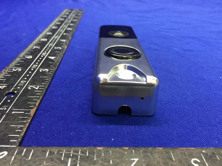
2ADXI-SBHD30
Dec 16, 2020SLIM LINE II
Equipment Class
NII - Unlicensed National Information Infrastructure TX
2ADXI-SK370-00020
Mar 05, 20152.4 GHz Wi-Fi Transceiver Module
Equipment Class
DTS - Digital Transmission System