2ADXI-SK370-000202.4 GHz Wi-Fi Transceiver Module
SkyBell Technologies Inc.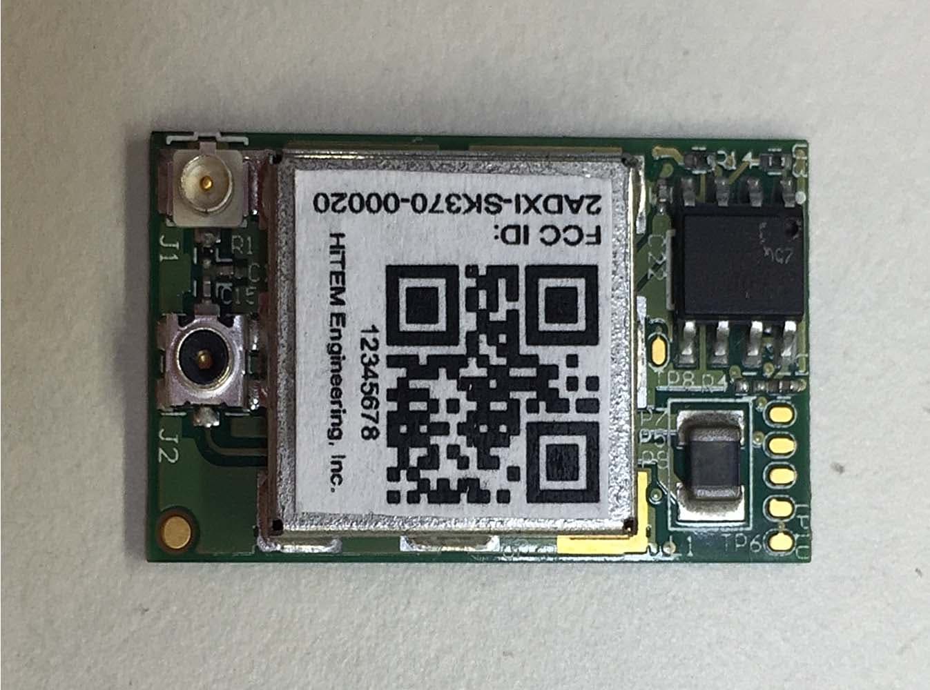
Click to zoom
Application Details
- Equipment Class
- DTS - Digital Transmission System
- Date of Grant
- Mar 05, 2015
- Application Purpose
- Original Equipment
- Date of Application
- Feb 24, 2015
- Equipment Note
- 2.4 GHz Wi-Fi Transceiver Module
- Frequency Range
- 2412.00000000 - 2472.00000000
- Company
- SkyBell Technologies Inc.
- Country
- United States
Documents & Files
Document Text
Text extracted from the exhibit documents filed with the FCC. Open a document above to read the original.
Users Manual
2.4 GHz Wi-Fi Module User Manual General Description The 2.4 GHz Wi-Fi module is an 802.11b/g/n solution containing RF frontend circuitry, baseband, MAC, Clock Management and Power Management for direct battery attach. The module is designed to be Placement of FCC ID on the finished product Use of this module requires placement of the FCC ID on the exterior of the finished product. The FCC ID must be visible on the exterior of the product and cannot be placed on a removable part. The FCC ID should be permanent (e.g. stamped, etched, engraved, printed with permanent ink or on a label with permanent adhesive, etc). Hand held devices may be permitted to place the FCC ID in the battery compartment under certain restrictions contained within KDB 784748 section 4: https://apps.fcc.gov/oetcf/kdb/forms/FTSSearchResultPage.cfm?id=27980&switch=P The finished product label must include the FCC ID of the incorporated module preceded by the phrase “This device contains” or any similar such verbiage conveying similar meaning: This device contains FCC ID: 2ADXI-SK370-00020 Or more simply: Contains FCC ID: 2ADXI-SK370-00020 Product Label Requirement The ID Label of the finished product must include the following statement. However, devices which are smaller than 4x4” are permitted to place this statement in the instruction manual, pamphlet or packaging in which the device is marketed. “This device complies with Part 15 of the FCC Rules. Operation is subject to the following two conditions: (1) this device may not cause harmful interference, and (2) this device must accept any interference received, including interference that may cause undesired operation..” Usage Restrictions “Changes or modifications not expressly approved by the party responsible for compliance could void the user's authority to operate the equipment.” Manual for Products Only one of the below statements is required to be in the finished product’s users manual, depending on whether the product is either Class A or Class B. Part 15 Class A Devices “Note: This equipment has been tested and found to comply with the limits for a Class A digital device, pursuant to part 15 of the FCC Rules. These limits are designed to provide reasonable protection against harmful interference when the equipment is operated in a commercial environment. This equipment generates, uses, and can radiate radio frequency energy and, if not installed and used in accordance with the instruction manual, may cause harmful interference to radio communications. Operation of this equipment in a residential area is likely to cause harmful interference in which case the user will be required to correct the interference at his own expense.” soldered to a PCB using with three external interfaces, power, SPI bus and u.fl antenna. The module is designed for use within the mobile devices category with the antenna placed greater than 20 cm from the body. The module comes fully tested and calibrated at the factory. Part 15 Class B Devices “This equipment has been tested and found to comply with the limits for a Class B digital device, pursuant to Part 15 of the FCC Rules. These limits are designed to provide reasonable protection against harmful interference in a residential installation. This equipment generates, uses and can radiate radio frequency energy and, if not installed and used in accordance with the instructions, may cause harmful interference to radio communications. However, there is no guarantee that interference will not occur in a particular installation. If this equipment does cause harmful interference to radio or television reception, which can be determined by turning the equipment off and on, the user is encouraged to try to correct the interference by one or more of the following measures: -- Reorient or relocate the receiving antenna. -- Increase the separation between the equipment and receiver. -- Connect the equipment into an outlet on a circuit different from that to which the receiver is connected. -- Consult the dealer or an experienced radio/TV technician for help” Electrical Data Absolute Maximum Ratings The absolute maximum ratings specify the values beyond which the device may be damaged permanently. Exposure to absolute maximum ratings conditions for extended periods of time may affect reliability. Each condition is applied with all other values kept within the recommended operating condition. Recommended Operating Conditions The recommended operating conditions specify the values in which region the device is operational meeting specification. SPI Interface Electrical Specification Current Consumption VBATT = 3.6 volts. Receiver Performance VBAT = 3.6 V, Tamb = 25°C. I/O Characteristics SPI timing characteristics SPI interface waveforms and timing are below: Reference Use Schematic Module Pinout Bottom View ICE_TDI ICE_TDO WLAN_SPI_CLK WLAN_SPI_EN/ WLAN_SPI_DIN WLAN_SPI_DOUT WLAN_SPI_IRQ FB1 BLM15PD121SN1D U6 GND 1 RESERVED_1 2 NC 3 RESERVED_2 4 WL_EN2 5 WL_RS232_TX 6 WL_EN1 7 WL_RS232_RX 8 GND 9 GND 10 GND 11 GND 16 SPI_IRQ 14 VBAT_IN 19 GND 18 SPI_DIN 15 SPI_CLK 17 SPI_CS 12 SPI_DOUT 13 GND 20 RESERVED_3 24 GND 25 VBAT_SW_EN 26 GND 34 ANT 35 GND 43 GND 44 GND 31 SDA_EEPROM 27 SDA_CC3000 28 SCL_EEPROM 29 SCL_CC3000 30 GND 32 GND 33 GND 36 GND 46 GND 45 VIO_HOST 23 GND 22 EXT_32K 21 C27 6pF C28 6pF WLAN_VBAT WLAN_S_EN ICE_TMS ICE_TCK ON WLAN Firmware The firmware is executed from on-chip ROM. Firmware patches are downloaded from host at Power on Reset, or loaded into RAM from a serial Flash Memory connected to the SPI interface. The firmware implements the full IEEE 802.11b/g/n wireless LAN MAC protocol, an embedded IP stack together with a few commonly used applications that can be easily configured and controlled via the chip interface. The wireless LAN MAC stack supports basic service set (BSS), Mobile AP and WiFi Direct. Low-level protocol functions such as RTS/CTS, acknowledgement, fragmentation, defragmentation, frame encapsulation (802…
Text truncated - open the document above for the full version.
Cover Letter(s)
1/6/2015 Federal Communications Commission 7435 Oakland Mills Road Columbia, MD 21046 Subject: Request for Permanent Confidentiality To whom it may concern: In accordance with 47CFR Section 0.457 and Section 0.459 pertaining to confidential material, we hereby request to hold permanently confidential all information contained within the below identified exhibits/document categories submitted pursuant to radio equipment certification requirements for FCC ID: 2ADXI-SK370-00020 1. Block Diagram 2. Operational Description 3. Schematics 4. Parts List / Tune-Up Procedure The above material contains trade secrets and proprietary information as specified by 47CFR 0.457(d) and technical data, which would customarily be guarded from competitors. The public disclosure of this information might be harmful to our company and provide unjustified benefits to our competitors. Sincerely, Seton Kasmir President and CEO HiTEM Engineering, INC. HiTEM ENGINEERING, INC. 7420 Carroll Road, San Diego, CA 92121
Cover Letter(s)
1/6/2015 Federal Communications Commission 7435 Oakland Mills Road Columbia, MD 21046 Subject: Request for Temporary Confidentiality To whom it may concern: In accordance with 47CFR Section 0.457 and Section 0.459, FCC Public Notice DA04-1705 and KDB Publication 726920 pertaining to confidential material, we hereby request to hold temporarily confidential all information contained within the below identified exhibits/document categories submitted pursuant to radio equipment certification requirements for FCC ID: 2ADXI-SK370-00020 for 180 days. 1. External Photos 2. Internal Photos 3. Test Setup Photos 4. User’s Manual 5. Block Diagram 6. Operational Description 7. Schematics 8. Parts List / Tune-Up Procedure The above material contains trade secrets and proprietary information as specified by 47CFR 0.457(d) and technical data, which would customarily be guarded from competitors. Pre-marketing public disclosure of this information might be harmful to our company and provide unjustified benefits to our competitors. Sincerely, Seton Kasmir President and CEO HiTEM Engineering, INC. HiTEM ENGINEERING, INC. 7420 Carroll Road, San Diego, CA 92121
Cover Letter(s)
1/6/2015 Federal Communications Commission Office of Engineering and Technology 7435 Oakland Mills Road Columbia, MD 21046 To Whom It May Concern: This letter is to request Limited Modular Approval in accordance with FCC Rule Part 15.212(b) for the certification request under FCC ID: 2ADXI-SK370-00020. This product is a 2.4 GHz Wi-Fi Transceiver Module and can be used in any Wi-Fi device. Declaration of conditions. Y/N 15.212(a)(1) Condition Y (i) The radio elements of the module have their own shielding. The physical crystal and tuning capacitors may be located external to the shielded radio elements Y (ii) The module has buffered modulation/data inputs (if such inputs are provided) to ensure that the module will comply with part 15 requirements under conditions of excessive data rates or over-modulation. Y (iii) The module has its own power supply regulation. Y (iv) The module complies with the antenna and transmission system requirements of §§15.203, 15.204(b) and 15.204(c). The antenna(s) are either permanently attached or employ a “unique” antenna coupler (at all connections between the module and the antenna, including the cable). Y (v) The module was tested in a stand-alone configuration, i.e., the module was not inside another device during testing for compliance with part 15 requirements. Unless the transmitter module will be battery powered, it complies with the AC line conducted requirements found in §15.207. AC or DC power lines and data input/output lines connected to the module do not contain ferrites, unless they will be marketed with the module (see §15.27(a)). The length of these lines was the length typical of actual use or, if that length is unknown, at least 10 centimeters was used to insure that there is no coupling between the case of the module and supporting equipment. Any accessories, peripherals, or support equipment connected to the module during testing were unmodified and commercially available (see §15.31(i)). Y (vi) The module is equipped with either a permanently affixed label or is capable of electronically displaying its FCC identification number. Y (vii) The module complies with any specific rules or operating requirements that ordinarily apply to a complete transmitter and the applicant has provided adequate instructions along with the module to explain any such requirements. Y (viii) The module complies with any applicable RF exposure requirements in its final configuration. The instructions provided with the module adequately explain any usage conditions or restrictions. HiTEM ENGINEERING, INC. 7420 Carroll Road, San Diego, CA 92121 Explanation of limitations for items not compliant with the above conditions. Section Detailed Explanations (if needed) List of additional restrictions or conditions of use for this module (optional). The module is to be used in one host, restricted to products controlled by HiTEM Engineering, INC. Methods used to address restrictions to ensure compliance for all finished products (optional). Desgined for use in products in the mobile RF category. The antenna is to be installed at a distance greater than 20 cm from from the body. I acknowledge on behalf of the applicant that compliance of this module in all final configurations is the responsibility of the applicant under the condition that the integrator follows all provided installation instructions. Sincerely, Seton Kasmir President and CEO HiTEM Engineering, INC.
ID Label/Location Info
Label and Placement for 2ADXI-SK370-00020Module ~ 11mm ~ 11mm Top side of module
RF Exposure Info
RADIO FREQUENCY EXPOSURE REPORT FOR THE Device: 2.4 GHz Transmitter Module Model: Skybell Report No.: 95696-26 Date of issue: February 20, 2015 Prepared For: HITEM 7420 Carroll Rd. San Diego CA, 92121 Prepared By: S Yamamoto CKC Laboratories, Inc. 5046 Sierra Pines Drive Mariposa, CA 95338 The test data contained in this report documents the observed testing parameters pertaining to and are relevant for only the sample equipment tested in the agreed upon operational mode(s) and configuration(s) as identified herein. Compliance assessment remains the client’s responsibility. This report may not be used to claim product endorsement by A2LA or any government agencies. This test report has been authorized for release under quality control from CKC Laboratories, Inc. Steve Behm Director of Quality Assurance & Engineering Services CKC Laboratories, Inc. Page 2 of 7 Report No: 95696-26 Purpose: To demonstrate compliance with United States, Canada and/or European Union RF Exposure requirements for Portable equipment (devices used ≤20cm from the body) or Mobile equipment (devices used >20cm from the body) with power output below exemption levels and Mobile equipment, where Maximum Permissible Exposure (MPE) Calculations apply. United States Compliance Requirements (1.1310): RF Exposure Evaluation Limits Occupational / Controlled Exposure Frequency Range (MHz) Electric Field Strength (V/m) Magnetic Field Strength (A/m) Power Density (mW/cm 2 ) Averaging Time (minutes) 0.3-3.0 614 1.63 *(100) 6 3.0-30 1842/f 4.89/f *(900/f 2 ) 6 30-300 61.4 0.163 1 6 300-1500 --- --- f/300 6 1500-100,000 --- --- 5.0 6 RF Exposure Evaluation Limits General Population / Uncontrolled Exposure Frequency Range (MHz) Electric Field Strength (V/m) Magnetic Field Strength (A/m) Power Density (mW/cm 2 ) Averaging Time (minutes) 0.3-1.34 614 1.63 *(100) 30 1.34-30 824/f 2.19/f *(180/f 2 ) 30 30-300 27.5 0.073 0.2 30 300-1500 --- --- f/1500 30 1500-100,000 --- --- 1.0 30 * Plane wave equivalent power density Limit is calculated based on the mid-band frequency used in the operating frequency range. Exemption Level: Power output <60/f GHz (mW) Page 3 of 7 Report No: 95696-26 Canadian Compliance Requirements (RSS-102): RF Exposure Evaluation Limits Occupational / Controlled Exposure: Frequency Range (MHz) Electric Field Strength (V/m) Magnetic Field Strength (A/m) Power Density (W/m 2 ) Averaging Time (minutes) 0.003-1.0 600 4.9 --- 6 1.0-10 600/f 4.9/f --- 6 10-30 60 4.9/f --- 6 30-300 60 0.163 10 6 300-1500 3.54 f 0.5 0.0094*f 0.5 f/3 6 1500-15,000 137 0.364 50 6 15,000-150,000 137 0.364 50 616000/f 1.2 RF Exposure Evaluation Limits General Population / Uncontrolled Exposure Frequency Range (MHz) Electric Field Strength (V/m) Magnetic Field Strength (A/m) Power Density (W/m 2 ) Averaging Time (minutes) 0.003-1.0 280 2.19 --- 6 1.0-10 280/f 2.19/f --- 6 10-30 28 2.19/f --- 6 30-300 28 0.073 2 6 300-1500 1.585 * f 0.5 0.0042 * f 0.5 f/150 6 1500-15,000 61.4 0.163 10 6 15,000-150,000 61.4 0.163 10 616000/f 1.2 *Power density limit applicable >100MHz Exemption Level: Frequency Range (MHz) Maximum Output Power (Conducted or EIRP) 0.003-1000 ≤ 200 mW 1000-2200 ≤ 100 mW 2200-3000 ≤ 20 mW 3000-6000 ≤ 10 mW Page 4 of 7 Report No: 95696-26 European Union Compliance Requirements (ICNIRP): RF Exposure Evaluation Limits Occupational / Controlled Exposure: Frequency Range (MHz) Electric Field Strength (V/m) Magnetic Field Strength (A/m) Power Density (W/m 2 ) Averaging Time (minutes) 0.00082-0.065 610 24.4 --- 6 0.065-1.0 610 1.6/f --- 1.0-10 610/f 1.6/f --- 6 10-400 61 0.16 10 6 400-2000 3.0 * f 0.5 0.008 * f 0.5 f/40 6 2000-300,000 137 0.36 50 6 RF Exposure Evaluation Limits General Population / Uncontrolled Exposure Frequency Range (MHz) Electric Field Strength (V/m) Magnetic Field Strength (A/m) Power Density (W/m 2 ) Averaging Time (minutes) 0.003-0.150 87 5.0 --- 6 0.150-1.0 87 0.73/f -- 6 1.0-10 87/f 0.5 0.73/f --- 6 10-400 28 0.073 2 6 400-2000 1.375 f 0.5 0.0037*f 0.5 f/200 6 2000-300,000 61 0.16 10 6 *Power density limit applicable >100MHz Exemption Level: Power output < 20mW 1 1 May vary by product type Page 5 of 7 Report No: 95696-26 Device and Antenna Operating Configuration: Device operating at maximum output power with continuous transmission of modulated data. The EUT antenna port is connected directly to the antenna without a cable. The antenna is oriented perpendicular to the pcba. The manufacturers declared antenna gain is 2dBi. The EUT is connected to a support located laptop computer via USB cable. The computer is running software Production Test GUI to setup EUT transmitting protocol. The test frequencies are 2412MHz, 2442MHz, and 2472MHz. An external DC power adapter is also connected to the wireless test fixture. Test Procedure: This equipment is evaluated in accordance with the guidelines set forth in OET Guide 65 & ANSI C95.1 for the US and Health Canada Safety Code 6 & RSS 102 for Canada. Other Considerations: None MPE Calculations Applicability: Limit Used X General Population / Uncontrolled Exposure Occupational / Controlled Exposure RF Exposure Exemption No United States No Canada Equipment operational details: Config # Operating Frequency (MHz) Measured Output Power (dBm) Antenna Gain (dBi) Antenna Type / Configuration EIRP (dBm) 1 2412 MHz to 2472 MHz 19.3 2.0 Ant1 21.3 Measurements based from EMC Test Report(s): 95696-19 MPE Calculation: 2 4d EIRP DensityPower Given: EIRP in mW or W and d in cm or m Config # Distance (cm) US (1.1310) Canada (RSS-102) Power Density (mW/cm 2 ) Limit (mW/cm 2 ) Power Density (W/m 2 ) Limit (W/m 2 ) 1 20 0.0268 1 0.268 10 Page 6 of 7 Report No: 95696-26 Summary: Exemptions: In the case the equipment meets compliance requirements by exemption the product is approved for use under mobile or portable conditions without further testing under the condition that any additional collocation or simultaneous transmission requirements (including necessary separation distances) have bee…
Text truncated - open the document above for the full version.
Test Report
This report contains a total of 57 pages and may be reproduced in full only. Partial reproduction may only be done with the written consent of CKC Laboratories, Inc. HITEM ADDENDUM TO TEST REPORT 95696-19 2.4 GHz Transmitter Module Model: Skybell Tested To The Following Standards: FCC Part 15 Subpart C Section(s) 15.247 Report No.: 95696-19A Date of issue: February 9, 2015 This test report bears the accreditation symbol indicating that the testing performed herein meets the test and reporting requirements of ISO/IEC 17025 under the applicable scope of EMC testing for CKC Laboratories, Inc. We strive to create long-term, trust based relationships by providing sound, adaptive, customer first testing services. We embrace each of our customers’ unique EMC challenges, not as an interruption to set processes, but rather as the reason we are in business. Page 2 of 57 Report No.: 95696-19A TABLE OF CONTENTS Administrative Information .......................................................................................................................... 3 Test Report Information ............................................................................................................................................ 3 Revision History ......................................................................................................................................................... 3 Report Authorization ................................................................................................................................................. 3 Test Facility Information ............................................................................................................................................ 4 Software Versions ...................................................................................................................................................... 4 Site Registration & Accreditation Information .......................................................................................................... 4 Summary of Results ................................................................................................................................................... 5 Modifications/Conditions During Testing .................................................................................................................. 5 Equipment Under Test ............................................................................................................................................... 6 Peripheral Devices ..................................................................................................................................................... 6 FCC Part 15 Subpart C ................................................................................................................................... 7 15.31(e) Voltage Variations ....................................................................................................................................... 7 15.247(a)(2) -6dB Occupied Bandwidth .................................................................................................................... 9 15.247(b)(3) RF Power Output ................................................................................................................................ 18 15.247(d) Conducted Spurious Emissions ............................................................................................................... 27 15.247(d) / 15.209 Radiated Spurious Emissions and Band Edge ........................................................................... 31 15. 247(e) Power Spectral Density .......................................................................................................................... 47 Supplemental Information .......................................................................................................................... 56 Measurement Uncertainty ...................................................................................................................................... 56 Emissions Test Details .............................................................................................................................................. 56 Page 3 of 57 Report No.: 95696-19A ADMINISTRATIVE INFORMATION Test Report Information REPORT PREPARED FOR: REPORT PREPARED BY: HITEM 7420 Carroll Rd San Diego, CA 92121 Terri Rayle CKC Laboratories, Inc. 5046 Sierra Pines Drive Mariposa, CA 95338 REPRESENTATIVE: Seton Kasmir Project Number: 95696 Customer Reference Number: 85 DATE OF EQUIPMENT RECEIPT: August 29, 2014 DATE(S) OF TESTING: August 29 – November 13, 2014 Revision History Original: Testing of 2.4 GHz Transmitter Module, Model: Skybell to FCC Part 15 Subpart C Section(s), 15.247. Addendum A: To replace the blank data plots in conducted spurious and radiated spurious emission sections (page 29 and 33) and added equipment to the table/list to cover the frequency range tested for radiated spurious emissions (page 31). Report Authorization The test data contained in this report documents the observed testing parameters pertaining to and are relevant for only the sample equipment tested in the agreed upon operational mode(s) and configuration(s) as identified herein. Compliance assessment remains the client’s responsibility. This report may not be used to claim product endorsement by A2LA or any government agencies. This test report has been authorized for release under quality control from CKC Laboratories, Inc. Steve Behm Director of Quality Assurance & Engineering Services CKC Laboratories, Inc. Page 4 of 57 Report No.: 95696-19A Test Facility Information Our laboratories are configured to effectively test a wide variety of product types. CKC utilizes first class test equipment, anechoic chambers, data acquisition and information services to create accurate, repeatable and affordable test results. TEST LO…
Text truncated - open the document above for the full version.
Contact Information
Applicant
Desiree Mejia(COO)
Test Firm
CKC Laboratories, Inc.Steve Behm
Technical Specifications
| # | Rule Parts | Frequency Range | Power Output |
|---|---|---|---|
| 1 | 15C | 2.41 GHz - 2.47 GHz | 85.00 mW |
Other Applications from SkyBell Technologies Inc.

2ADXI-SBHD50
Mar 03, 2021TRIM II PRO
Equipment Class
DTS - Digital Transmission System
2ADXI-SBHD30
Dec 16, 2020SLIM LINE II
Equipment Class
NII - Unlicensed National Information Infrastructure TX
2ADXI-SBHD20
Nov 10, 2020TRIM II PRO
Equipment Class
NII - Unlicensed National Information Infrastructure TX