2ADXI-SBHD30SLIM LINE II
SkyBell Technologies Inc.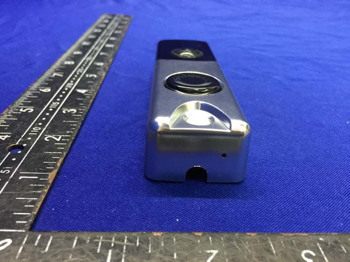
Click to zoom
Application Details
- Equipment Class
- NII - Unlicensed National Information Infrastructure TX
- Date of Grant
- Dec 16, 2020
- Application Purpose
- Original Equipment
- Date of Application
- Dec 16, 2020
- Equipment Note
- SLIM LINE II
- Frequency Range
- 5745.00000000 - 5825.00000000
- Company
- SkyBell Technologies Inc.
- Country
- United States
Documents & Files
Document Text
Text extracted from the exhibit documents filed with the FCC. Open a document above to read the original.
Users Manual
. Fi 802.11 b/g/n, 2.4 GHz up to 150 Mbps-Wi ompatible with CUpload speed of 2 Mbps is required. Wi-Fi . camera doorbell sent may result in damage to the chime is not pre Failure to install a resistor when a . demonstration or performing a the doorbell when testing e This is typically don chime. home doorbell-wired, in Alarm.com. SkyBell V1 and V2 cameras are not compatible with SkyBell V1 and V2 Not Compatible . platform Alarm.com the with may not be compatible Alarm.com, not purchased through s, Certain SkyBell HD camera SkyBell HD Cameras atform. pl h as the SkyBell suc, other platforms and apps •Alarm.com Slim Line II Doorbell Camera •Alarm.com Wi-Fi Doorbell Camera, SkyBell-HD Edition w ith Alarm.com: following Doorbell Cameras are fully compatible The s Doorbell Camera Alarm.com Masonry anchors • Wall screws • Wall mounting bracket • NCLUDED MATERIALSI on.for more informati alarm.com/doorbell Visit time alerts.-receive real triggered automation rules and Customers can also record doorbell triggered clips, set motion all right from their app. – way audio -visitors via two the door and speak to s peaker, enabling homeowners to answer integrated camera, PIR motion sensor, digital microphone and a doorbell with an amera featuresEach Alarm.com Doorbell C even more customers! easy to deliver front door awareness to it’s – Fi Doorbell Camera and our new Slim Line -Wiour original – from amera. Now with two options to choose Doorbell CAlarm.com Your customers will always know who is at the front door with an INTRODUCTION INSTALLATION GUIDE ALARM.COM DOORBELL CAMERA DEVICE COMPATIBILITY WITH ALARM.COM Slim Line II Incompatible with SkyBell and Other Platforms The Slim Line II D oorbell Camera is not compatible with REQUIREMENTS Power and Chime Type 10-30VAC, wired to a n in-h ome mechanical or digital doorbell chime. Note: A Digital Doorbell Adapter must be installed if a digital doorbell chime is present. See below for more information. WARNING: An in-line resistor (10 Ohm, 10 Watt) is required when installing the doorbell camera without a Slim Line II Cop yright © 2017 Alarm.com | www.alarm.com | May 2017 2 Wi-Fi Doorbell Camera - HD and Slim Line Editions | Installation Guide Mobile App Download the latest Alarm.com Mobile App for iOS or Android (version 4.4.1 or higher for video streaming). Mounting The mounting plate affixes to a flat surface (a power drill may be required) and uses the existing doorbell wiring. The equipment is only suitable for mounting at heights ≤ 2 m. P RE-I NSTALLATION CHECKLIST Working Doorbell Check A wired doorbell circuit is required to provide power to the doorbell camera. First check that the existing wired doorbell is working and that it is wired properly. There is a power issue if the existing doorbell does not ring the indoor chime when the button is pressed. This issue must be addressed before beginning the doorbell camera installation process. Wired Doorbell Check Check that the existing doorbell is wired by visually inspecting the doorbell button for wires. If necessary, the doorbell can be removed from the wall to check for wiring. Y ou can also inspect the chime inside the home – a chime plugged into a power outlet might indicate an incompatible wireless doorbell system is in place. Doorbell Chime Type Check Locate the chime inside the home and remove the faceplate. Identify the chime as one of the following types: Mechanical Chime – If the chime has metal bars and a striker pin, it is mechanical and will work without additional hardware. Digital Chime - If the chime has a speaker that plays a tone when pressed, it is digital and will require the installation of the Digital Doorbell Adapter and the enabling of the digital doorbell setting in the app to function properly. Tube Chime - If the chime has a series of tubular bells, it is a tube chime and is incompatible with the doorbell camera. Intercom System – If the doorbell button fixture includes a speaker, it is an intercom system and is incompatible with the doorbell camera. No Chime – If there is no chime in the system, the customer will only receive alerts on their phone and a res istor (10 Ohm 10 Watt) must be used in-line with the doorbell camera. Digital Doorbell Adapter The Digital Doorbell Adapter is available for purchase through the Alarm.com Dealer Website. Wi-Fi Password Check Make sure you have the password for the Wi-Fi network in the home where you plan to install the doorbell camera. Verify the Wi-Fi credentials before you begin by connecting a smartphone or laptop to the Wi-Fi network and attempting to access a website. Internet & Wi-Fi Speed Check A Wi-Fi I nternet upload speed of at least 2 Mbps is required at the location where the doorbell camera is installed. Follow these steps to check the connection speed: 1. Go to the location where the doorbell camera will be installed 2. Close the door 3. Disable the cellular (LTE) Internet connection on your device and connect to the home’s 2.4 GHz Wi-Fi network 4. Run a speed test (for example, SpeedOf.me or speedtest.net) to determine the Internet speed 5. In the test results, note the Upload speed. The Alarm.com Wi-Fi D oorbell Cameras re quire an upload speed of at least 2 Mbps. Cop yright © 2017 Alarm.com | www.alarm.com | May 2017 3 Wi-Fi Doorbell Camera - HD and Slim Line Editions | Installation Guide HARDWARE INSTALLATION Use Alarm.com Doorbell Camera Hardware Alarm.com’s Doorbell Camera hardware must be used: •Alarm.com Wi-Fi Doorbell Camera •Alarm.com Slim Line II Doorbell Camera S kyB ell HD consumer hardware is not supported. Slim Line Doorbell Camera hardware is not supported on the SkyBell platform or other service provider platforms. Remove Existing Doorbell Button Take care to prevent the existing doorbell wires from slipping into the wall. Attach the Doorbell Mounting Bracket to the Wall Feed the existing doorbell wires through the hole in the center of the bracket. Affix the bracket firmly to the wall by driving the pro…
Text truncated - open the document above for the full version.
Attestation Statements
SKYBELL TECHNOLOGIES INC Date: 2020-12-04 To: Federal Communications Commission 7435 Oakland Mills Road Columbia, MD FCC ID: 2ADXI-SBHD30 T o Whom It May Concern: T his letter is to ascertain that SKYBELL TECHNOLOGIES INC EUT:SLIM LINE II MO DEL No.: ADC-VDB105X, ADC-VDB106X Has been the units used for conducting FCC compliance testing, the SDoC part will be tested by EMTEK (SHENZHEN) CO., LTD. If you have any question or concerns, pls. contact us. Sincerely, Client’s signature : Client’s name / title : Desiree Mejia Contact information / address: SKYBELL TECHNOLOGIES INC /1 Jenner Ste 100, Irvien CA 92618, USA
Cover Letter(s)
Rev 11/20/07 SKYBELL TECHNOLOGIES INC Federal Communications Commission Authorization and Evaluation Division Confidentiality Request regarding application for certification of FCC ID: 2ADXI-SBHD30 Pursuant to Sections 0.457 and 0.459 of the Commission’s Rules, we hereby request confidential treatment of information accompanying this application as outlined below: Exhibit Type File Name Block Diagram, Schematics, Operational Description, Block Diagram Operation Description schematic diagram The above materials contain trade secrets and proprietary information not customarily released to the public. The public disclosure of these materials may be harmful to the applicant and provide unjustified benefits to its competitors. Client’s name / title : Desiree Mejia Contact information / address: SKYBELL TECHNOLOGIES INC /1 Jenner Ste 100, Irvine CA 92618, USA
Cover Letter(s)
SKYBELL TECHNOLOGIES INC Company Address : 1 Jenner Ste 100, Irvine CA 92618, USA Date : 2020-12-04 DTS-UNII Device Declaration Letter To whom it may concern : We have declared below featured for FCC equipment authorization, Device FCC ID : 2ADXI-SBHD30 (1) DFS Device -- Master , Client with Radar detection capability , Client without radar detection capability , N/A (2) Active / Passive Scanning , adhoc mode access point capability Frequency Band (MHz) Active Scanning (the device can transmit a probe (beacon)) passive scanning (where the device is can listen only with no probes) Ad Hoc Mode or WIFI Direct capability Access point capability 5180-5240 Yes , No Yes , No Yes , No Yes , No 5260-5320 Yes , No Yes , No Yes , No Yes , No 5745-5825 Yes , No Yes , No Yes , No Yes , No 5190-5230 Yes , No Yes , No Yes , No Yes , No 5270-5310 Yes , No Yes , No Yes , No Yes , No 5755-5795 Yes , No Yes , No Yes , No Yes , No 5210-5210 Yes , No Yes , No Yes , No Yes , No 5290-5290 Yes , No Yes , No Yes , No Yes , No 5775-5775 Yes , No Yes , No Yes , No Yes , No (3) Country code selection ability - Yes , No If yes, pls explain how it was implemented : (pls also help to provide detail of options for each country selection) (4) Meet 15.202 requirement - Yes , No , pls check below : A master device is defined as a device operating in a mode in which it has the capability to transmit without receiving an enabling signal. In this mode it is able to select a channel and initiate a network by sending enabling signals to other devices A client device is defined as a device operating in a mode in which the transmissions of the device are under control of the master. A device in client mode is not able to initiate a network. (5) For client devices that have software configuration control to operate in different modes (active scanning in some and passive scanning in others) in different bands (devices with multiple equipment classes or those that operate on non-DFS frequencies) or modular devices which configure the modes of operations through software, the application must provide software and operations description on how the software and / or hardware is implemented to ensure that proper operations modes can not be modified by end user or an installer. Apply , No Apply , (If apply , pls help to provide explanation on it was implement , and how software was controlled) Signature : Client’s name / title : Desiree Mejia /COO Contact information / address: SKYBELL TECHNOLOGIES INC /1 Jenner Ste 100, Irvine CA 92618, USA
Cover Letter(s)
Declaration on model difference We the undersigned hereby confirm that any of our production units bearing the following model numbers are identical in circuitry and electrical, mechanical and physical construction; the only differences are the model name and the color of appearance for trading purpose. FCC ID: 2ADXI-SBHD30 Production name Trade name Model no. SLIM LINE II SKYBELL ADC-VDB105X, ADC-VDB106X Co nfirmed by SKYBELL TECHNOLOGIES INC Client’s name / title : Desiree Mejia /COO Contact information / address: SKYBELL TECHNOLOGIES INC /1 Jenner Ste 100, Irvine CA 92618, USA Date: _2020-12- 04
Cover Letter(s)
SKYBELL TECHNOLOGIES INC Federal Communications Commission Authorization and Evaluation Division 1435 Oakland Mills Road Columbia, MD 21046 Date: 2020-12-04 SUBJECT: FCC Application for FCC ID: 2ADXI-SBHD30 To Whom It May Concern: We, the undersigned, hereby authorize Lisa Wang at EMTEK (SHENZHEN) CO., LTD. on our behalf, to apply to the Federal Communications Commission on our equipment. Any and all acts carried out by EMTEK (SHENZHEN) CO., LTD. on our behalf shall have the same effect as acts of our own. This is to advise that we are in full compliance with the Anti- Drug Abuse Act. We, the applicant, are not subject to a denial of federal benefits pursuant to Section 5301 of the Anti-Drug Act of 1988, 21 USC853a, and no party to the application is subject to a denial of federal benefits pursuant to that section. Client’s name / title : Desiree Mejia/COO Contact information / address: SKYBELL TECHNOLOGIES INC /1 Jenner Ste 100, Irvine CA 92618, USA
External Photos
EUT EXTERNAL PHOTOGRAPHS EUT View 1 EUT View 2 EUT View 3 EUT View 4 EUT View 5 EUT View 6 ----------------The end----------------
ID Label/Location Info
Label and label location
Internal Photos
EUT INTERNAL PHOTOGRAPHS EUT Housing and Board View 1 EUT Housing and Board View 2 EUT Housing and Board View 3 Solder Board-Component View 1 Solder Board-Component View 2 Solder Board-Component View 3 Solder Board-Component View 4 Battery Antenna ----------------The end---------------- Ant 1 Ant 2
RF Exposure Info
FCC ID : 2ADXI-SBHD30 RF EXPOSURE EVALUATION According to FCC 1.1310: The criteria listed in the following table shall be used to evaluate the environment impact of human exposure to radio frequency (RF) Radiation as specified in §1.1307(b) Limits for Maximum Permissible Exposure (MPE) Frequency Range(MHz) Electric Field Strength(V/m) Magnetic Field Strength(A/m) Power Density(mW/cm 2 ) Average Time (A) Limits for Occupational/Control Exposures 300-1500 -- -- F/300 6 1500-100000 -- -- 5 6 (B) Limits for General Population/Uncontrol Exposures 300-1500 -- -- F/1500 6 1500-100000 -- -- 1 30 11.1 Friis transmission formula: Pd= (Pout*G)\ (4*pi*R 2 ) Where Pd= Power density in mW/cm 2 Pout=output power to antenna in mW G= Numeric gain of the antenna relative to isotropic antenna Pi=3.1416 R= distance between observation point and center of the radiator in cm Pd the limit of MPE, 1mW/cm 2 ,If we know the maximum gain of the nd total power input to the antenna, through the calculation, we will know the distance where the MPE limit is reached. RF Exposure Information: The radiated output power of this device meets the limits of FCC/IC radio frequency exposure limits.This device should be operated with a minimum separation distance of 20cm (8 inches) between the equipment and a person's body. 11.2 Measurement Result WIFI2.4G and WIFI5G cannot transmit at the same time Wifi 2.4G Antenna gain: 3.59 dBi modulation Channel Freq. (MHz) Measured power (dBm) Tune-up power (dBm) Max tune-up power (dBm) Antenna Gain Numeric Evaluation result (mW/cm2 ) Power density Limits (mW/cm2 ) 802.11n (HT20) 2412 21.59 20 to 22 22 2.29 0.0722 1 2437 22.24 21 to 23 23 2.29 0.0909 1 2462 21.50 20 to 22 22 2.29 0.0722 1 802.11n (HT40) 2422 23.84 22 to 24 24 2.29 0.1144 1 2437 23.58 22 to 24 24 2.29 0.1144 1 2452 23.12 22 to 24 24 2.29 0.1144 1 Wifi 5G Antenna gain: 3.59 dBi modulation Measured power (dBm) Tune-up power (dBm) Max tune-up power (dBm) Antenna Gain Numeric Evaluation result (mW/cm2 ) Power density Limits (mW/cm2 ) 5150MHz-5250MHz 15.72 14 to16 16 2.29 0.0181 1 5250MHz-5350MHz 15.03 14 to16 16 2.29 0.0181 1 5470MHz-5725MHz 18.10 17 to19 19 2.29 0.0362 1 5725MHz-5875MHz 19.41 18 to20 20 2.29 0.0456 1
Test Report
Report No.ES201123021W02 Page 1 of 193 Ver.1.0 TEST REPORT Product Name : SLIM LINE II Model Number : ADC-VDB105X, ADC-VDB106X FCC ID : 2ADXI-SBHD30 Prepared for : SKYBELL TECHNOLOGIES INC Address : 1 JENNER STE 100, IRVINE CA 92618, USA Prepared by : EMTEK (SHENZHEN) CO., LTD. Address : Building 69, Majialong Industry Zone, Nanshan District, Shenzhen, Guangdong, China Tel: (0755) 26954280 Fax: (0755) 26954282 Report Number : ES201123021W02 Date(s) of Tests : August 20, 2020 to November 30, 2020 Date of issue : December 1, 2020 $二维码$ Report No.ES201123021W02 Page 2 of 193 Ver.1.0 1 TEST RESULT CERTIFICATION Applicant : SKYBELL TECHNOLOGIES INC Address : 1 JENNER STE 100, IRVINE CA 92618, USA Manufacturer : SKYBELL TECHNOLOGIES INC Address : 1 JENNER STE 100, IRVINE CA 92618, USA EUT : SLIM LINE II Model Name : ADC-VDB105X, ADC-VDB106X Trademark : SKYBELL Measurement Procedure Used: APPLICABLE STANDARDS STANDARD TEST RESULT FCC 47 CFR Part 2, Subpart J FCC 47 CFR Part 15, Subpart E PASS The above equipment was tested by EMTEK (SHENZHEN) CO., LTD. The test data, data evaluation, test procedures, and equipment configurations shown in this report were made in accordance with the procedures given in ANSI C63.10 (20 13) and the energy emitted by the sample EUT tested as described in this report is in compliance with the requirements of FCC Rules Part 2 and Part 15.407 The test results of this report relate only to the tested sample identified in this report. Date of Test : August 20, 2020 to November 30, 2020 Prepared by: Sewen Guo /Editor Reviewer: Joe Xia /Supervisor Approve & Authorized Signer : Lisa Wang/Manager Report No.ES201123021W02 Page 3 of 193 Ver.1.0 TABLE OF CONTENTS 1 TEST RESULT CERTIFICATION ............................................................................................................... 2 2 EUT TECHNICAL DESCRIPTION ............................................................................................................. 4 3 SUMMARY OF TEST RESULT .................................................................................................................... 7 4 TEST METHODOLOGY ............................................................................................................................... 8 4.1 GENERAL DESCRIPTION OF APPLIED STANDARDS ...................................................................... 8 4.2 MEASUREMENT EQUIPMENT USED ................................................................................................. 8 4.3 DESCRIPTION OF TEST MODES .......................................................................................................... 9 5 FACILITIES AND ACCREDITATIONS .................................................................................................... 13 5.1 FACILITIES............................................................................................................................................ 13 5.2 LABORATORY ACCREDITATIONS AND LISTINGS ........................................................................ 13 6 TEST SYSTEM UNCERTAINTY ............................................................................................................... 14 7 SETUP OF EQUIPMENT UNDER TEST .................................................................................................. 15 7.1 RADIO FREQUENCY TEST SETUP .................................................................................................... 15 7.2 RADIO FREQUENCY TEST SETUP .................................................................................................... 15 7.3 CONDUCTED EMISSION TEST SETUP ............................................................................................. 17 7.4 BLOCK DIAGRAM CONFIGURATION OF TEST SYSTEM .............................................................. 18 7.5 SUPPORT EQUIPMENT........................................................................................................................ 18 8 TEST REQUIREMENTS ............................................................................................................................. 19 8.1 BANDWIDTH MEASUREMENT ......................................................................................................... 19 8.2 MAXIMUM CONDUCTED OUTPUT POWER.................................................................................... 67 8.3 MAXIMUM PEAK POWER DENSITY ................................................................................................ 81 8.4 FREQUENCY STABILITY .................................................................................................................. 151 8.5 UNDESIRABLE RADIATED SPURIOUS EMISSION ....................................................................... 160 8.6 POWER LINE CONDUCTED EMISSIONS ........................................................................................ 189 8.7 ANTENNA APPLICATION ................................................................................................................. 192 Report No.ES201123021W02 Page 4 of 193 Ver.1.0 2 EUT TECHNICAL DESCRIPTION Characteristics Description Product: SLIM LINE II Model Number: ADC-VDB105X, ADC-VDB106X (All models covered in this report are the same with each other, except for different model and appearance (for color, silk-screen only) for trading purpose. We choose ADC-VDB105X as the final test prototype) Sample Number: 2# Wifi Type: Wifi 5G with 5150MHz-5250MHz Band Wifi 5G with 5250MHz-5350MHz Band Wifi 5G with 5470MHz-5725MHz Band Wifi 5G with 5725MHz-5850MHz Band WLAN Supported: 802.11a 802.11n(20MHz channel bandwidth) 802.11n(40MHz channel bandwidth) 802.11ac(20MHz channel bandwidth) 802.11ac(40MHz channel bandwidth) 802.11ac(80MHz channel bandwidth) Data Rate : 802.11a:54/48/36/24/18/12/9/6Mbps 802.11n:up to 300 Mbps 802.11ac:up to 867Mbps Modulation: OFDM with BPSK/QPSK/16QAM/64QAM for 802.11a/n; OFDM with BPSK/QPSK/16QAM/64QAM/256QA…
Text truncated - open the document above for the full version.
Test Report
Report No.ES201123021W02 Page 50 of 193 Ver.1.0 26dB Occupied Bandwidth U-NII - 3 Test Model 802.11ac(HT20) Frequency(MHz) 5825 26dB Occupied Bandwidth U-NII - 3 Test Model 802.11n-HT40 Frequency(MHz) 5755 Report No.ES201123021W02 Page 51 of 193 Ver.1.0 26dB Occupied Bandwidth U-NII - 3 Test Model 802.11n-HT40 Frequency(MHz) 5795 26dB Occupied Bandwidth U-NII - 3 Test Model 802.11ac(HT40) Frequency(MHz) 5755 Report No.ES201123021W02 Page 52 of 193 Ver.1.0 26dB Occupied Bandwidth U-NII - 3 Test Model 802.11ac(HT40) Frequency(MHz) 5795 26dB Occupied Bandwidth U-NII - 3 Test Model 802.11ac 80 Frequency(MHz) 5775 Report No.ES201123021W02 Page 53 of 193 Ver.1.0 99% Occupied Bandwidth U-NII - 3 Test Model 802.11a Frequency(MHz) 5745 99% Occupied Bandwidth U-NII - 3 Test Model 802.11a Frequency(MHz) 5785 Report No.ES201123021W02 Page 54 of 193 Ver.1.0 99% Occupied Bandwidth U-NII - 3 Test Model 802.11a Frequency(MHz) 5825 99% Occupied Bandwidth U-NII - 3 Test Model 802.11n-HT20 Frequency(MHz) 5745 Report No.ES201123021W02 Page 55 of 193 Ver.1.0 99% Occupied Bandwidth U-NII - 3 Test Model 802.11n-HT20 Frequency(MHz) 5785 99% Occupied Bandwidth U-NII - 3 Test Model 802.11n-HT20 Frequency(MHz) 5825 Report No.ES201123021W02 Page 56 of 193 Ver.1.0 99% Occupied Bandwidth U-NII - 3 Test Model 802.11ac(HT20) Frequency(MHz) 5745 99% Occupied Bandwidth U-NII - 3 Test Model 802.11ac(HT20) Frequency(MHz) 5785 Report No.ES201123021W02 Page 57 of 193 Ver.1.0 99% Occupied Bandwidth U-NII - 3 Test Model 802.11ac(HT20) Frequency(MHz) 5825 99% Occupied Bandwidth U-NII - 3 Test Model 802.11n-HT40 Frequency(MHz) 5755 Report No.ES201123021W02 Page 58 of 193 Ver.1.0 99% Occupied Bandwidth U-NII - 3 Test Model 802.11n-HT40 Frequency(MHz) 5795 99% Occupied Bandwidth U-NII - 3 Test Model 802.11ac(HT40) Frequency(MHz) 5755 Report No.ES201123021W02 Page 59 of 193 Ver.1.0 99% Occupied Bandwidth U-NII - 3 Test Model 802.11ac(HT40) Frequency(MHz) 5795 99% Occupied Bandwidth U-NII - 3 Test Model 802.11ac 80 Frequency(MHz) 5775 Report No.ES201123021W02 Page 60 of 193 Ver.1.0 6db Emission Bandwidth U-NII - 3 Test Model 802.11a Frequency(MHz) 5745 6db Emission Bandwidth U-NII - 3 Test Model 802.11a Frequency(MHz) 5785 Report No.ES201123021W02 Page 61 of 193 Ver.1.0 6db Emission Bandwidth U-NII - 3 Test Model 802.11a Frequency(MHz) 5825 6db Emission Bandwidth U-NII - 3 Test Model 802.11n-HT20 Frequency(MHz) 5745 Report No.ES201123021W02 Page 62 of 193 Ver.1.0 6db Emission Bandwidth U-NII - 3 Test Model 802.11n-HT20 Frequency(MHz) 5785 6db Emission Bandwidth U-NII - 3 Test Model 802.11n-HT20 Frequency(MHz) 5825 Report No.ES201123021W02 Page 63 of 193 Ver.1.0 6db Emission Bandwidth U-NII - 3 Test Model 802.11ac(HT20) Frequency(MHz) 5745 6db Emission Bandwidth U-NII - 3 Test Model 802.11ac(HT20) Frequency(MHz) 5785 Report No.ES201123021W02 Page 64 of 193 Ver.1.0 6db Emission Bandwidth U-NII - 3 Test Model 802.11ac(HT20) Frequency(MHz) 5825 6db Emission Bandwidth U-NII - 3 Test Model 802.11n-HT40 Frequency(MHz) 5755 Report No.ES201123021W02 Page 65 of 193 Ver.1.0 6db Emission Bandwidth U-NII - 3 Test Model 802.11n-HT40 Frequency(MHz) 5795 6db Emission Bandwidth U-NII - 3 Test Model 802.11ac(HT40) Frequency(MHz) 5755 Report No.ES201123021W02 Page 66 of 193 Ver.1.0 6db Emission Bandwidth U-NII - 3 Test Model 802.11ac(HT40) Frequency(MHz) 5795 6db Emission Bandwidth U-NII - 3 Test Model 802.11ac 80 Frequency(MHz) 5775 Report No.ES201123021W02 Page 67 of 193 Ver.1.0 8.2 MAXIMUM CONDUCTED OUTPUT POWER 8.2.1 Applicable Standard According to FCC Part 15.407(a)(1) for UNII Band I According to FCC Part 15.407(a)(2) for UNII Band II-A and UNII Band II-C According to FCC Part 15.407(a)(3) for UNII Band III According to 789033 D02 Section II(E) 8.2.2 Conformance Limit For the band 5.15-5.25 GHz, (a) (1) (i) For an outdoor access point operating in the band 5.15-5.25 GHz, the maximum conducted output power over the frequency band of operation shall not exceed 1 W provided the maximum antenna gain does not exceed 6 dBi. In addition, the maximum power spectral density shall not exceed 17 dBm in any 1 megahertz band. If transmitting antennas of directional gain greater than 6 dBi are used, both the maximum conducted output power and the maximum power spectral density shall be reduced by the amount in dB that the directional gain of the antenna exceeds 6 dBi. The maximum e.i.r.p. at any elevation angle above 30 degrees as measured from the horizon must not exceed 125 mW (21 dBm). (a) (1) (ii) For an indoor access point operating in the band 5.15-5.25 GHz, the maximum conducted output power over the frequency band of operation shall not exceed 1 W provided the maximum antenna gain does not exceed 6 dBi. In addition, the maximum power spectral density shall not exceed 17 dBm in any 1 megahertz band. If transmitting antennas of directional gain greater than 6 dBi are used, both the maximum conducted output power and the maximum power spectral density shall be reduced by the amount in dB that the directional gain of the antenna exceeds 6 dBi. (a) (1) (iii) For fixed point-to-point access points operating in the band 5.15-5.25 GHz, the maximum conducted output power over the frequency band of operation shall not exceed 1 W. In addition, the maximum power spectral density shall not exceed 17 dBm in any 1 megahertz band. Fixed point-to-point U-NII devices may employ antennas with directional gain up to 23 dBi without any corresponding reduction in the maximum conducted output power or maximum power spectral density. For fixed point-to-point transmitters that employ a directional antenna gain greater than 23 dBi, a 1 dB reduction in maximum conducted output power and maximum power spectral density is required for each 1 dB of antenna gain in excess of 23 dBi. Fixed, point-to-point operations exclude the use of point-to-multipoint systems, omnidirectional applications, and multiple collocated transmitters transmitting the same information. The operator of …
Text truncated - open the document above for the full version.
Test Report
Report No.ES201123021W02 Page 89 of 193 Ver.1.0 Power Spectral Density U-NII - 1 Test Model 802.11n-HT40 Frequency(MHz) 5230 Power Spectral Density U-NII - 1 Test Model 802.11ac(HT40) Frequency(MHz) 5190 Report No.ES201123021W02 Page 90 of 193 Ver.1.0 Power Spectral Density U-NII - 1 Test Model 802.11ac(HT40) Frequency(MHz) 5230 Power Spectral Density U-NII - 1 Test Model 802.11ac 80 Frequency(MHz) 5210 Report No.ES201123021W02 Page 91 of 193 Ver.1.0 5250-5350MHz Operating mode Test Channel Power Spectral Density dBm/MHz Limit (dBm/MHz) 802.11a 5260 1.513 11 5280 1.346 11 5320 1.437 11 802.11n-HT20 5260 0.076 11 5280 -0.203 11 5320 -0.062 11 802.11ac(HT20) 5260 0.092 11 5280 -0.084 11 5320 -0.405 11 802.11n-HT40 5270 -6.130 11 5310 -6.431 11 802.11ac(HT40) 5270 -6.265 11 5310 -8.882 11 802.11ac(HT80) 5290 -9.657 11 Report No.ES201123021W02 Page 92 of 193 Ver.1.0 Power Spectral Density U-NII – 2A Test Model 802.11a Frequency(MHz) 5260 Power Spectral Density U-NII – 2A Test Model 802.11a Frequency(MHz) 5280 Report No.ES201123021W02 Page 93 of 193 Ver.1.0 Power Spectral Density U-NII – 2A Test Model 802.11a Frequency(MHz) 5320 Power Spectral Density U-NII – 2A Test Model 802.11n-HT20 Frequency(MHz) 5260 Report No.ES201123021W02 Page 94 of 193 Ver.1.0 Power Spectral Density U-NII – 2A Test Model 802.11n-HT20 Frequency(MHz) 5280 Power Spectral Density U-NII – 2A Test Model 802.11n-HT20 Frequency(MHz) 5320 Report No.ES201123021W02 Page 95 of 193 Ver.1.0 Power Spectral Density U-NII – 2A Test Model 802.11ac(HT20) Frequency(MHz) 5260 Power Spectral Density U-NII – 2A Test Model 802.11ac(HT20) Frequency(MHz) 5280 Report No.ES201123021W02 Page 96 of 193 Ver.1.0 Power Spectral Density U-NII – 2A Test Model 802.11ac(HT20) Frequency(MHz) 5320 Power Spectral Density U-NII – 2A Test Model 802.11n-HT40 Frequency(MHz) 5270 Report No.ES201123021W02 Page 97 of 193 Ver.1.0 Power Spectral Density U-NII – 2A Test Model 802.11n-HT40 Frequency(MHz) 5310 Power Spectral Density U-NII – 2A Test Model 802.11ac(HT40) Frequency(MHz) 5270 Report No.ES201123021W02 Page 98 of 193 Ver.1.0 Power Spectral Density U-NII – 2A Test Model 802.11ac(HT40) Frequency(MHz) 5310 Power Spectral Density U-NII – 2A Test Model 802.11ac 80 Frequency(MHz) 5290 Report No.ES201123021W02 Page 99 of 193 Ver.1.0 5470-5725MHz Operating mode Test Channel Power Spectral Density dBm/MHz Limit (dBm/MHz) 802.11a 5500 3.332 11 5580 4.788 11 5700 3.658 11 802.11n-HT20 5500 2.026 11 5580 3.493 11 5700 2.083 11 802.11ac(HT20) 5500 1.609 11 5580 3.369 11 5700 1.658 11 802.11n-HT40 5510 -3.299 11 5670 -3.062 11 802.11ac(HT40) 5510 -3.572 11 5670 -3.400 11 802.11ac(HT80) 5530 -6.540 11 Report No.ES201123021W02 Page 100 of 193 Ver.1.0 Power Spectral Density U-NII – 2C Test Model 802.11a Frequency(MHz) 5500 Power Spectral Density U-NII – 2C Test Model 802.11a Frequency(MHz) 5580 Report No.ES201123021W02 Page 101 of 193 Ver.1.0 Power Spectral Density U-NII – 2C Test Model 802.11a Frequency(MHz) 5700 Power Spectral Density U-NII – 2C Test Model 802.11n-HT20 Frequency(MHz) 5500 Report No.ES201123021W02 Page 102 of 193 Ver.1.0 Power Spectral Density U-NII – 2C Test Model 802.11n-HT20 Frequency(MHz) 5580 Power Spectral Density U-NII – 2C Test Model 802.11n-HT20 Frequency(MHz) 5700 Report No.ES201123021W02 Page 103 of 193 Ver.1.0 Power Spectral Density U-NII – 2C Test Model 802.11ac(HT20) Frequency(MHz) 5500 Power Spectral Density U-NII – 2C Test Model 802.11ac(HT20) Frequency(MHz) 5580 Report No.ES201123021W02 Page 104 of 193 Ver.1.0 Power Spectral Density U-NII – 2C Test Model 802.11ac(HT20) Frequency(MHz) 5700 Power Spectral Density U-NII – 2C Test Model 802.11n-HT40 Frequency(MHz) 5510 Report No.ES201123021W02 Page 105 of 193 Ver.1.0 Power Spect…
Text truncated - open the document above for the full version.
Contact Information
Applicant
Desiree Mejia(COO)
Test Firm
EMTEK (Shenzhen) Co., Ltd.Lisa Wang
[email protected]86 755 26954280
Technical Specifications
| # | Rule Parts | Frequency Range | Power Output |
|---|---|---|---|
| 4 | 15E | 5.75 GHz - 5.83 GHz | 87.00 mW |
Other Applications from SkyBell Technologies Inc.

2ADXI-SBHD50
Mar 03, 2021TRIM II PRO
Equipment Class
DTS - Digital Transmission System
2ADXI-SBHD20
Nov 10, 2020TRIM II PRO
Equipment Class
NII - Unlicensed National Information Infrastructure TX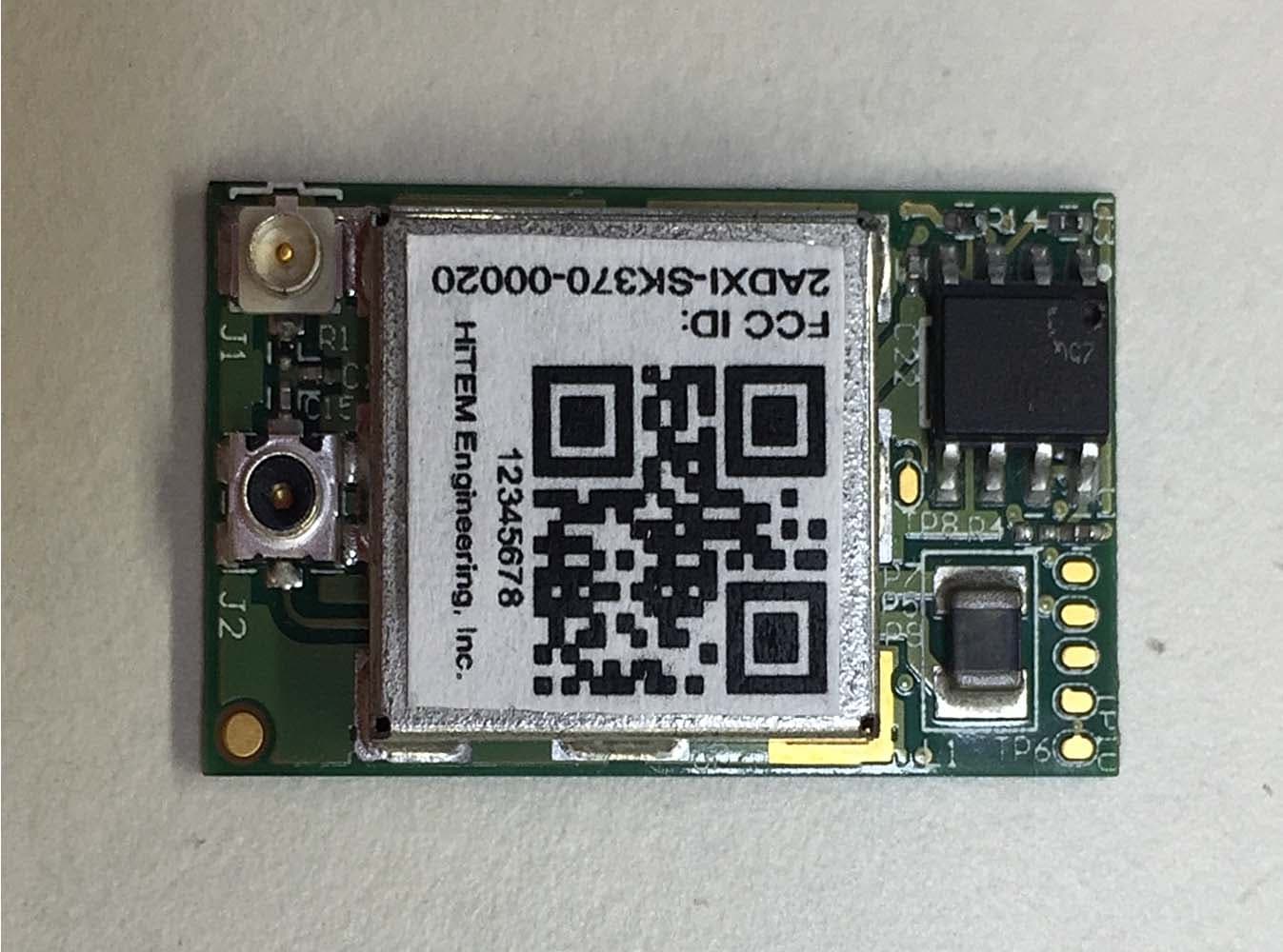
2ADXI-SK370-00020
Mar 05, 20152.4 GHz Wi-Fi Transceiver Module
Equipment Class
DTS - Digital Transmission System