2ADXI-SBHD50TRIM II PRO
SkyBell Technologies Inc.
Click to zoom
Application Details
- Equipment Class
- DTS - Digital Transmission System
- Date of Grant
- Mar 03, 2021
- Application Purpose
- Original Equipment
- Date of Application
- Mar 03, 2021
- Equipment Note
- TRIM II PRO
- Frequency Range
- 2412.00000000 - 2462.00000000
- Company
- SkyBell Technologies Inc.
- Country
- United States
Documents & Files
Document Text
Text extracted from the exhibit documents filed with the FCC. Open a document above to read the original.
Users Manual
TRIMIIPRO DoorbellCamera PRODUCT FEATURES HD VIDEO See your visitor up to 1080p HD and 5x zoom. MOTION SENSOR SkyBell alerts you even if visitor doesn’t press button – providing additional security. LIVE MONITORING Monitor your front door at any time by starting the video from the app. FREE VIDEO RECORDING SkyBell can record each video so you download or watch them at any time. MULTIPLE USERS Multiple people can receive alerts to answer the door and you can have multiple device on each account. HEAR & SPEAK 2 way audio means you can enjoy a full conversation with your visitor. ACTIVITY HISTORY Review the day’s events while you were away – includes missed visitors, answered video calls and motion alerts. COLOR NIGHT VISION Feel safe knowing you can see a visitor at night – in full color HD video QUIET MODE Turn off your home’s doorbell chime from the app so it won’t wake up a baby! SNAP PHOTOS Capture a photo of your visitor with the touch of a button RUGGED Only SkyBell can work between -40 and 140 degrees F THEFT GUARANTEE If your SkyBell is stolen, we will replace it free of charge. PRODUCT DESIGN TECHNICAL SPECIFICATIONS Power: 10-30VAC, 50/60Hz,0.5A Max or12VDC,0.5 to1.0A wired to in home mechanical chime - digital doorbell chime compatibility requires SkyBell Digital Doorbell Adapter - not included TRIM2S TRIM2B Wi-Fi : 802.11 b/g/n/ac, 2.4 and 5 GHz Upload bandwidth: 2 Mbps required Mounting: Mounting plate affixes to flat surface and utilizes existing doorbell wiring Mobile device: Alarm.com app compatible with Apple iOS, Android Specifications Video camera: 1080p resolution, 180° view Night vision: IR up to 16 feet (5 m) Audio: Built-in speaker and microphone Motion sensor: PIR detects motion up to 10 feet Dimensions: 1.4 in/3.7 cm wide ; 4.8 in/12.2 cm tall 1.1 in/2.9 cm deep, 3.1 oz/87.9 g weight Environment: operating temp -40°F/-40°C to 113°F/45°C Exclusively for systems powered by Alarm.com *Alarm.com app required. Not compatible with the Sky Bell app. MOTION SENSOR The motion sensor on the SkyBell Trim Plus contains a Fresnel lens. This is a flat lens made of a number of concentric rings, to reduce spherical aberration. Spherical aberration is a loss of definition in the image arising from the surface geometry of a spherical mirror or lens. This enhances the accuracy of motion detection, which will improve your overall SkyBell experience. The SkyBell device uses a PIR sensor (passive infrared sensor), which is an electronic sensor that measures infrared light radiating in the field of view; think flood lights or motion detectors for your alarm system. When the PIR sensor senses activity (meets a certain threshold) and is activated, it immediately turns the camera on and starts to record directly to the device. This activation triggers an initial motion event. The SkyBell continues monitoring this activity energy from the PIR sensor and when meeting a more stringent threshold, it sends a notification to the phone. If the notification is answered, the SkyBell records for as long as the activity is detected. If the notification is not answered, the SkyBell records for 30 seconds in addition to the initial motion event, approximately 35-40 seconds. Once the recording is complete, the device sends the video to the SkyBell cloud servers, where it can be accessed almost immediately and is kept for seven (7) days. CLOUD RECORDING Available with all SkyBell devices. Choosing a SkyBell Device from the Devices List takes the user to the “Activity Page” and allows them to access the videos. There are no subscription fees. Recordings can be “downloaded” to the user’s iOS or Android device. Recordings are saved for seven (7) days and will be automatically deleted starting with the oldest. All recordings are saved to the SkyBell Cloud Server and pushed to the user’s account. Recordings are activated when: motion is detected; the doorbell is pressed; or the user initiates a “watch live” on-demand call. The SkyBell records for 30 seconds plus the addition of the initial motion event, approximately 35-40 seconds. Recording include audio and video. Attach the Doorbell Mounting Bracket to the Wall Feed the existing doorbell wires through the hole in the center of the bracket. Affix the bracket firmly to the wall by driving the provided wall screws through the top and bottom holes in the bracket. Failure to make the bracket flush on the wall could cause a poor power connection between the bracket and the doorbell camera. Connect Power Wires to the Mounting Bracket Loosen the terminal screws and insert the wires beneath the screws. Do not short (touch together) the wires during this process. Tighten the screws. The wires must be of approximately equal thickness, and the screws should be tightened approximately the same amount so that the screwheads are flush. If the wires are thick, splice short lengths of additional thinner wire. The splice joints can be hidden inside the wall, and the thinner wire can be used to connect to the mounting bracket. Attach the Doorbell Camera to the Mounting Bracket Slide the top of the doorbell camera down on to the mounting bracket and push the front of the doorbell camera toward the wall. Tighten the set screw located on the bottom of the camera, being careful not to damage it (power tools should not be used with the set screw). The camera’s LED should begin to illuminate. LED COLORS, BUTTON FUNCTIONS AND GENERAL TROUBLESHOOTING Battery Charging If the LED is alternating between Red and Blue (HD Edition) or pulsing Blue(Slim Line), the doorbell camera’s battery is charging. The duration of the presyncing charge process varies due to differences in existing doorbell circuits but normally takes less than 30 minutes. See the Power Information and Troubleshooting section if this state persists. Wi-Fi Connectivity If the LED is flashing Orange, the doorbell needs to be manually placed into AP mode. Press and hold the Main Button until the LE…
Text truncated - open the document above for the full version.
Attestation Statements
SKYBELL TECHNOLOGIES INC Date: 2020-12-28 To: Federal Communications Commission 7435 Oakland Mills Road Columbia, MD FCC ID: 2ADXI-SBHD50 To Whom It May Concern: This letter is to ascertain that SKYBELL TECHNOLOGIES INC EUT:SLIM LINE II MODEL No.: TRIM2 S, TRIM2 B Has been the units used for conducting FCC compliance testing, the SDoC part will be tested by EMTEK (SHENZHEN) CO., LTD. If you have any question or concerns, pls. contact us. Sincerely, Client’s signature : Client’s name / title : Desiree Mejia Contact information / address: SKYBELL TECHNOLOGIES INC / 1 JENNER STE 100, IRVINE CA 92618, USA
Cover Letter(s)
Rev 11/20/07 SKYBELL TECHNOLOGIES INC Federal Communications Commission Authorization and Evaluation Division Confidentiality Request regarding application for certification of FCC ID: 2ADXI-SBHD50 Pursuant to Sections 0.457 and 0.459 of the Commission’s Rules, we hereby request confidential treatment of information accompanying this application as outlined below: Exhibit Type File Name Block Diagram, Schematics, Operational Description, Block Diagram Operation Description schematic diagram The above materials contain trade secrets and proprietary information not customarily released to the public. The public disclosure of these materials may be harmful to the applicant and provide unjustified benefits to its competitors. Client’s name / title : Desiree Mejia Contact information / address: SKYBELL TECHNOLOGIES INC / 1 JENNER STE 100, IRVINE CA 92618, USA
Cover Letter(s)
SKYBELL TECHNOLOGIES INC Company Address : 1 JENNER STE 100, IRVINE CA 92618, USA Date : 2020-12-28 DTS-UNII Device Declaration Letter To whom it may concern : We have declared below featured for FCC equipment authorization, Device FCC ID : 2ADXI-SBHD50 (1) DFS Device -- Master , Client with Radar detection capability , Client without radar detection capability , N/A (2) Active / Passive Scanning , adhoc mode access point capability Frequency Band (MHz) Active Scanning (the device can transmit a probe (beacon)) passive scanning (where the device is can listen only with no probes) Ad Hoc Mode or WIFI Direct capability Access point capability 5180-5240 Yes , No Yes , No Yes , No Yes , No 5260-5320 Yes , No Yes , No Yes , No Yes , No 5745-5825 Yes , No Yes , No Yes , No Yes , No 5190-5230 Yes , No Yes , No Yes , No Yes , No 5270-5310 Yes , No Yes , No Yes , No Yes , No 5755-5795 Yes , No Yes , No Yes , No Yes , No 5210-5210 Yes , No Yes , No Yes , No Yes , No 5290-5290 Yes , No Yes , No Yes , No Yes , No 5775-5775 Yes , No Yes , No Yes , No Yes , No (3) Country code selection ability - Yes , No If yes, pls explain how it was implemented : (pls also help to provide detail of options for each country selection) (4) Meet 15.202 requirement - Yes , No , pls check below : A master device is defined as a device operating in a mode in which it has the capability to transmit without receiving an enabling signal. In this mode it is able to select a channel and initiate a network by sending enabling signals to other devices A client device is defined as a device operating in a mode in which the transmissions of the device are under control of the master. A device in client mode is not able to initiate a network. (5) For client devices that have software configuration control to operate in different modes (active scanning in some and passive scanning in others) in different bands (devices with multiple equipment classes or those that operate on non-DFS frequencies) or modular devices which configure the modes of operations through software, the application must provide software and operations description on how the software and / or hardware is implemented to ensure that proper operations modes can not be modified by end user or an installer. Apply , No Apply , (If apply , pls help to provide explanation on it was implement , and how software was controlled) Signature : Client’s name / title : Desiree Mejia Contact information / address: SKYBELL TECHNOLOGIES INC /1 JENNER STE 100, IRVINE CA 92618, USA
Cover Letter(s)
Declaration on model difference We the undersigned hereby confirm that any of our production units bearing the following model numbers are identical in circuitry and electrical, mechanical and physical construction; the only differences are themodel name and the color of appearance for trading purpose. Production nameTrade nameModel no. TRIM II PROSKYBELLTRIM2 S,TRIM2 B Confirmed by Skybell Technologies Inc DesireeMejia SkybellTechnologiesInc Date:2020-12-22
Cover Letter(s)
SKYBELL TECHNOLOGIES INC Federal Communications Commission Authorization and Evaluation Division 1435 Oakland Mills Road Columbia, MD 21046 Date: 2020-12-28 SUBJECT: FCC Application for FCC ID: 2ADXI-SBHD50 To Whom It May Concern: We, the undersigned, hereby authorize Lisa Wang at EMTEK (SHENZHEN) CO., LTD. on our behalf, to apply to the Federal Communications Commission on our equipment. Any and all acts carried out by EMTEK (SHENZHEN) CO., LTD. on our behalf shall have the same effect as acts of our own. This is to advise that we are in full compliance with the Anti- Drug Abuse Act. We, the applicant, are not subject to a denial of federal benefits pursuant to Section 5301 of the Anti-Drug Act of 1988, 21 USC853a, and no party to the application is subject to a denial of federal benefits pursuant to that section. Client’s name / title : Desiree Mejia Contact information / address: SKYBELL TECHNOLOGIES INC / 1 JENNER STE 100, IRVINE CA 92618, USA
External Photos
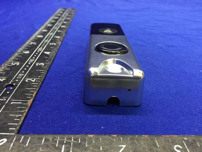
EUT EXTERNAL PHOTOGRAPHS EUT View 1 EUT View 2 EUT View 3 EUT View 4 EUT View 5 EUT View 6 ----------------The end----------------
ID Label/Location Info
Label and label location Trim II 电池防水贴-组合 Jessie Ng V1 1. 符合RoHS标准; 2. 制品中不可含有六价铬、镉、铅、水银、PBB(多溴化联 苯)、PBDE等物质; 3. 制品中氯系和溴系化合物含量900PPM以下,且两者 总和1500PPM以下,红磷100PPM以下。 1. Comply with RoHS standard; 2. Products should not contain hexavalent chromium, cadmium, lead, mercury, PBB (polybro- minated biphenyl), PBDE and other substances; 3. The content of chlorine and bromine compounds in the product is below 900PPM, and the sum of the two is below 1500PPM, and the red phosphorus is below 100PPM. 要 求 Requirementspecification 规 格 1. 尺寸:见上模切图 2. 材料:正面为PC/厚度0.25mm,表面为磨砂面; 背面为3M-467双面胶/厚度0.05; 3. 特殊要求:此贴纸需要有UL969认证证书; 4. 注意:印刷清楚,无脏污等不良。 1. Size: See the die-cut above 2. Material: The front is PC/thickness 0.25mm, the surface is frosted; The back is 3M-467 double-sided tape / thickness 0.05mm; 3. Special requirements: This label need UL969 certification; 4. Note: The printing is clear, no dirt and other defects. NameDRN Revise date CHK APR P/N Unit Ver 20201120
Internal Photos
EUT INTERNAL PHOTOGRAPHS EUT Housing and Board View 1 EUT Housing and Board View 2 EUT Housing and Board View 3 Solder Board-Component View 1 Solder Board-Component View 2 Solder Board-Component View 3 Solder Board-Component View 4 Solder Board-Component View 5 Battery Antenna ----------------The end---------------- Ant 1 Ant 2
RF Exposure Info
FCC ID : 2ADXI-SBHD50 RF EXPOSURE EVALUATION According to FCC 1.1310: The criteria listed in the following table shall be used to evaluate the environment impact of human exposure to radio frequency (RF) Radiation as specified in §1.1307(b) Limits for Maximum Permissible Exposure (MPE) Frequency Range(MHz) Electric Field Strength(V/m) Magnetic Field Strength(A/m) Power Density(mW/cm 2 ) Average Time (A) Limits for Occupational/Control Exposures 300-1500 -- -- F/300 6 1500-100000 -- -- 5 6 (B) Limits for General Population/Uncontrol Exposures 300-1500 -- -- F/1500 6 1500-100000 -- -- 1 30 11.1 Friis transmission formula: Pd= (Pout*G)\ (4*pi*R 2 ) Where Pd= Power density in mW/cm 2 Pout=output power to antenna in mW G= Numeric gain of the antenna relative to isotropic antenna Pi=3.1416 R= distance between observation point and center of the radiator in cm Pd the limit of MPE, 1mW/cm 2 ,If we know the maximum gain of the nd total power input to the antenna, through the calculation, we will know the distance where the MPE limit is reached. RF Exposure Information: The radiated output power of this device meets the limits of FCC/IC radio frequency exposure limits.This device should be operated with a minimum separation distance of 20cm (8 inches) between the equipment and a person's body. 11.2 Measurement Result WIFI2.4G and WIFI5G cannot transmit at the same time Wifi 2.4G Antenna gain: 3.59 dBi modulation Channel Freq. (MHz) Measured power (dBm) Tune-up power (dBm) Max tune-up power (dBm) Antenna Gain Numeric Evaluation result (mW/cm2 ) Power density Limits (mW/cm2 ) 802.11n (HT20) 2412 16.79 15 to 17 17 2.29 0.0228 1 2437 17.08 16 to 18 18 2.29 0.0287 1 2462 16.95 15 to 17 17 2.29 0.0228 1 802.11n (HT40) 2422 14.13 13 to 15 15 2.29 0.0144 1 2437 14.01 13 to 15 15 2.29 0.0144 1 2452 14.24 13 to 15 15 2.29 0.0144 1 Wifi 5G Antenna gain: 3.59 dBi modulation Measured power (dBm) Tune-up power (dBm) Max tune-up power (dBm) Antenna Gain Numeric Evaluation result (mW/cm2 ) Power density Limits (mW/cm2 ) 5150MHz-5250MHz 15.93 14 to16 16 2.29 0.0181 1 5250MHz-5350MHz 17.24 16 to18 18 2.29 0.0287 1 5470MHz-5725MHz 18.85 17 to19 19 2.29 0.0362 1 5725MHz-5875MHz 19.51 18 to20 20 2.29 0.0456 1
Test Report
Report No.ES201209053W01 Page 1 of 58 Ver.1.0 TEST REPORT Product Name : TRIM II PRO Model Number : TRIM2 S,TRIM2 B FCC ID : 2ADXI-SBHD50 Prepared for : SKYBELL TECHNOLOGIES INC Address : 1 JENNER STE 100, IRVINE CA 92618, USA Prepared by : EMTEK (SHENZHEN) CO., LTD. Address : Building 69, Majialong Industry Zone, Nanshan District, Shenzhen, Guangdong, China Tel: (0755) 26954280 Fax: (0755) 26954282 Report Number : ES201209053W01 Date(s) of Tests : December 13,2020 to December 25, 2020 Date of issue : December 28, 2020 $二维码$ Report No.ES201209053W01 Page 2 of 58 Ver.1.0 TABLE OF CONTENTS 1 TEST RESULT CERTIFICATION ...................................................................................................................... 3 2 EUT TECHNICAL DESCRIPTION .................................................................................................................... 4 3 SUMMARY OF TEST RESULT ........................................................................................................................... 5 4 TEST METHODOLOGY ...................................................................................................................................... 6 4.1 GENERAL DESCRIPTION OF APPLIED STANDARDS ............................................................................ 6 4.2 MEASUREMENT EQUIPMENT USED ....................................................................................................... 6 4.3 DESCRIPTION OF TEST MODES ................................................................................................................ 7 5 FACILITIES AND ACCREDITATIONS ............................................................................................................. 8 5.1 FACILITIES.................................................................................................................................................... 8 5.2 LABORATORY ACCREDITATIONS AND LISTINGS ................................................................................ 8 6 TEST SYSTEM UNCERTAINTY ........................................................................................................................ 9 7 SETUP OF EQUIPMENT UNDER TEST ......................................................................................................... 10 7.1 RADIO FREQUENCY TEST SETUP 1 ........................................................................................................ 10 7.2 RADIO FREQUENCY TEST SETUP 2 ........................................................................................................ 10 7.3 CONDUCTED EMISSION TEST SETUP .................................................................................................... 11 7.4 BLOCK DIAGRAM CONFIGURATION OF TEST SYSTEM .................................................................... 12 7.5 SUPPORT EQUIPMENT.............................................................................................................................. 12 8 TEST REQUIREMENTS .................................................................................................................................... 13 8.1 DTS (6DB) BANDWIDTH ........................................................................................................................... 13 8.2 MAXIMUM PEAK CONDUCTED OUTPUT POWER .............................................................................. 20 8.3 MAXIMUM POWER SPECTRAL DENSITY ............................................................................................. 22 8.4 UNWANTED EMISSIONS IN NON-RESTRICTED FREQUENCY BANDS ............................................ 37 8.5 RADIATED SPURIOUS EMISSION ........................................................................................................... 42 8.6 CONDUCTED EMISSIONS TEST .............................................................................................................. 54 8.7 ANTENNA APPLICATION ......................................................................................................................... 57 Report No.ES201209053W01 Page 3 of 58 Ver.1.0 1 TEST RESULT CERTIFICATION Applicant : SKYBELL TECHNOLOGIES INC Address : 1 JENNER STE 100, IRVINE CA 92618, USA Manufacturer : SKYBELL TECHNOLOGIES INC Address : 1 JENNER STE 100, IRVINE CA 92618, USA EUT : TRIM II PRO Model Name : TRIM2 S,TRIM2 B Trademark : SKYBELL Measurement Procedure Used: APPLICABLE STANDARDS STANDARD TEST RESULT FCC 47 CFR Part 2 , Subpart J FCC 47 CFR Part 15 , Subpart C PASS The above equipment was tested by EMTEK (SHENZHEN) CO., LTD. The test data, data evaluation, test procedures, and equipment configurations shown in this report were made in accordance with the procedures given in ANSI C63.10 (2013) and the energy emitted by the sample EUT tested as described in this report is in compliance with the requirements of FCC Rules Part 2 and Part 15.247 The test results of this report relate only to the tested sample identified in this report. Date of Test : December 13,2020 to December 25, 2020 Prepared by : Sewen Guo /Editor Reviewer : Joe Xia/Editor Approve & Authorized Signer : Lisa Wang/Manager Report No.ES201209053W01 Page 4 of 58 Ver.1.0 2 EUT TECHNICAL DESCRIPTION Note: for more details, please refer to the User’s manual of the EUT. Characteristics Description Product TRIM II PRO Model Number TRIM2 S,TRIM2 B (All models covered in this report are the same with each other, except for different model and appearance (for color, silk-screen only) for trading purpose. We choose TRIM2 S as the final test prototype) Sample Number 2# IEEE 802.11 WLAN Mode Supported 802.11b 802.11g 802.11n(20MHz channel bandwidth) 802.11n(40MHz channel bandwidth) Modulation DSSS with DBPSK/DQPSK/CCK for 802.11b; OFDM with BPSK/QPSK/16QAM/64QAM for 802.11g/n; Operating Frequency Range 2412-2462MHz for 802.11b/g/n(HT20); 2422-2452MHz for 802.11n(HT40); Number of Channels 11 channels for 802.11b/g n(…
Text truncated - open the document above for the full version.
Test Setup Photos
TEST SETUP PHOTOGRAPHS 1.1. Photos of Conducted Emission Measurement 1.2. Photos of Radiation Emission Measurement Spurious Emission Test Setup (Below 1GHz) Spurious Emission Test Setup (Above 1GHz) ----------------The end----------------
Contact Information
Applicant
Desiree Mejia(COO)
Test Firm
EMTEK (Shenzhen) Co., Ltd.Lisa Wang
[email protected]86 755 26954280
Technical Specifications
| # | Rule Parts | Frequency Range | Power Output |
|---|---|---|---|
| 1 | 15C | 2.41 GHz - 2.46 GHz | 51.00 mW |
Other Applications from SkyBell Technologies Inc.
2ADXI-SBHD30
Dec 16, 2020SLIM LINE II
Equipment Class
NII - Unlicensed National Information Infrastructure TX
2ADXI-SBHD20
Nov 10, 2020TRIM II PRO
Equipment Class
NII - Unlicensed National Information Infrastructure TX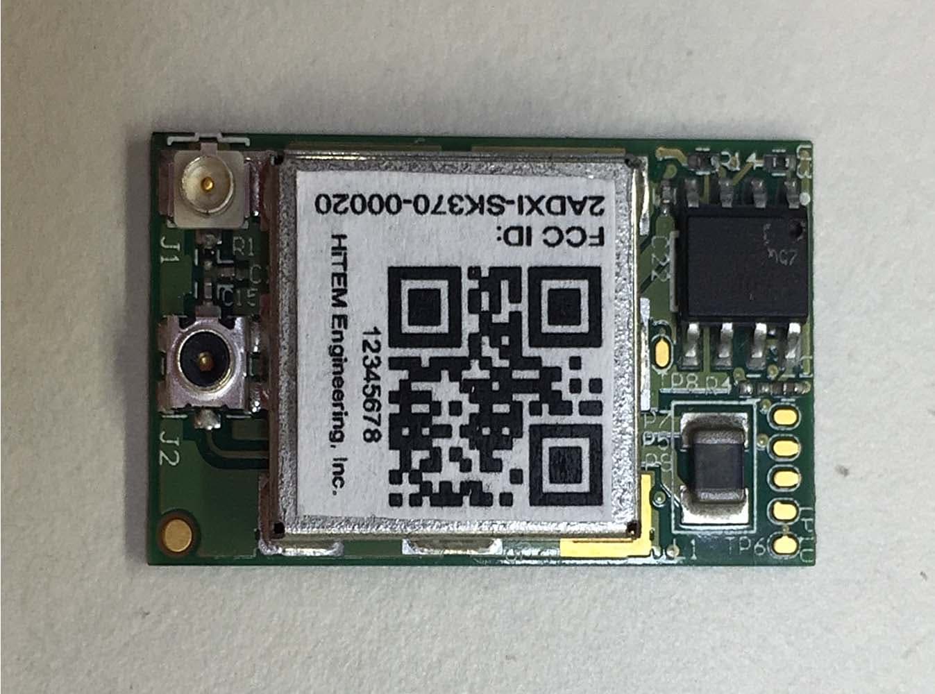
2ADXI-SK370-00020
Mar 05, 20152.4 GHz Wi-Fi Transceiver Module
Equipment Class
DTS - Digital Transmission System