2AEBXET4271Remote Control
EGLO Hong Kong Lighting Ltd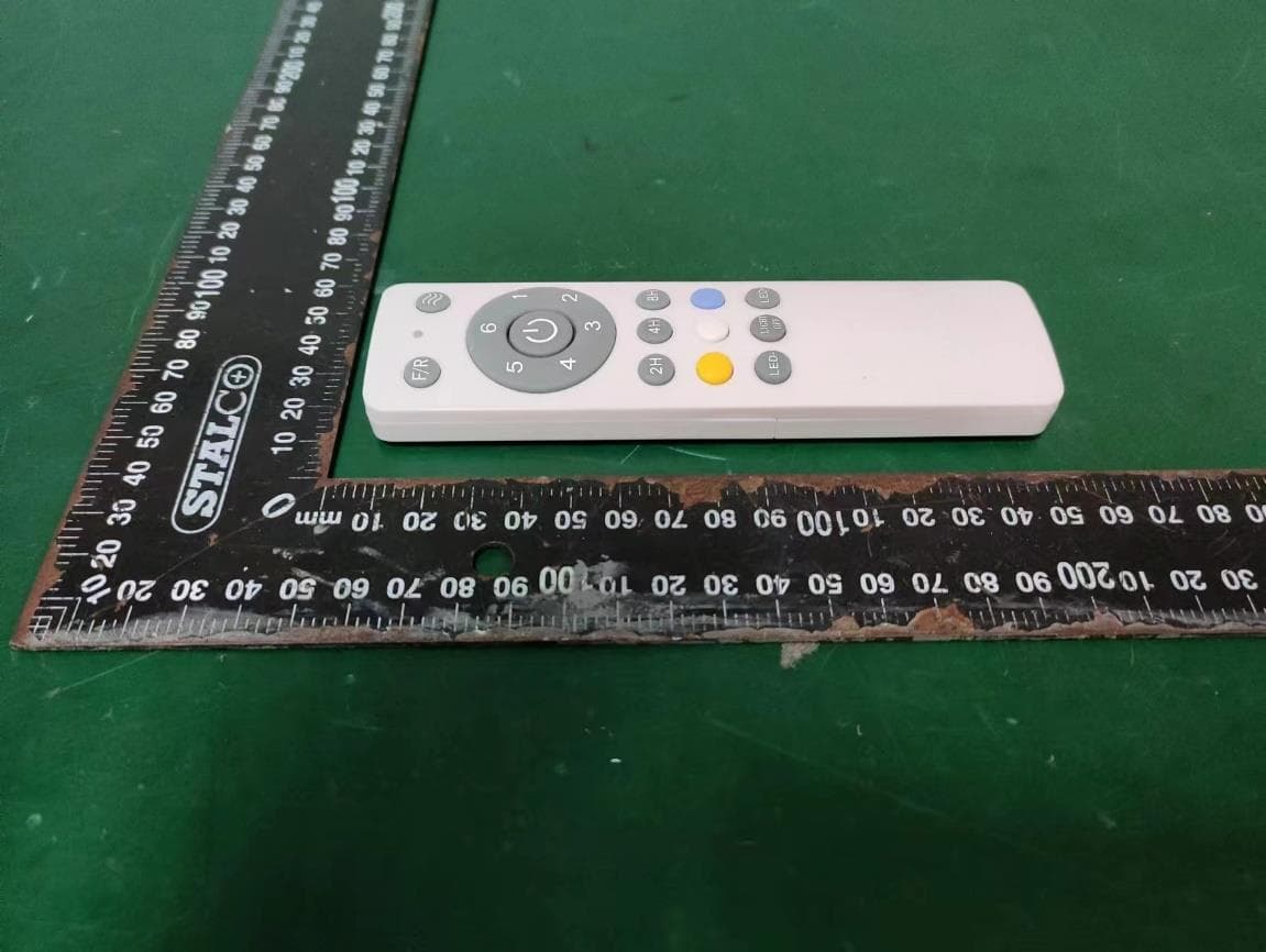
Click to zoom
Application Details
- Equipment Class
- DSC - Part 15 Security/Remote Control Transmitter
- Date of Grant
- Oct 24, 2023
- Application Purpose
- Original Equipment
- Date of Application
- Oct 07, 2023
- Equipment Note
- Remote Control
- Frequency Range
- 433.92000000 - 433.92000000
- Company
- EGLO Hong Kong Lighting Ltd
- Country
- China
Documents & Files
Document Text
Text extracted from the exhibit documents filed with the FCC. Open a document above to read the original.
Users Manual
INSTALLATION INSTRUCTION FOR CEILING FAN REMOTE CONTROLLER MODEL NO. OF RECEIVER: AA-24DC2023-8RFMODEL NO. OF TRANSMITTER: II2019-18T4 IMPORTANT POINTS: 1. Please read this instruction, and save it for further use. 2. Before installation, TURN OFF THE POWER OF YOUR CEILING FAN. 3. Please note that all wiring appliances should be installed by a qualified electrician. 4. This unit is to be used in a 100-130V~ 50/60Hz supply only. (Rating: RECEIVER: Max40W for fan motor, Max 20W for LED. TRANSMITTER: transmitting frequency range:433.92MHz±300kHz, Maximum transmitting power: 8dBm.) 5. Do not install in damp locations or immerse in water. (For indoor use only.)6. Do not pull on or cut leads shorter.7. Do not drop or bump the unit. 8. PLEASE NOTE: The battery will weaken with age and should be replaced before leaking takes place as this will damage the transmitter. 9. The batteries must be removed from the transmitter before it is scrapped. And the batteries shall be disposed of safety. 10. The switch shall be mounted at a height greater than 1.7m.11. The electric shock protection of the RF receiver shall be depended on its installation.12. The RF remote controller shall be used within its rating range, otherwise overheating and dangerous phenomenon may occur. 13. The RF ceiling fan remote controller is made by XIN HUI A.A. ELECTRONICS LTD.14. CAUTON: To reduce the risk of fire or injury, do not use this product in conjunction with any variable (rheostat) wall control. 15. Warning: Changes or modifications to this unit not expressly approved by the party responsible for compliance could void the user’s authority to operate the equipment. 16. This device complies with Part 15 of the FCC Rules. Operation is subject to the following two conditions: (1) this device may not cause harmful interference, and (2) this device must accept any interference received, including interference that may cause undesired operation. 17. NOTE: This equipment has been tested and found to comply with the limits for a Class B digital device, pursuant to Part 15 of the FCC Rules. This limits are designed to provide reasonable protection against harmful interference in a residential installation. This equipment generates uses and can radiate radio frequency energy and, if not installed and used inaccordance with the instructions, may cause harmful interference to radio communications. However, there is no guarantee that interference will not occur in a particular installation. If this equipment does cause harmful interference to radio or television reception, which can be determined by turning the equipment off and on, the user is encouraged to try to correct theinterference by one or more of the following measures: □ Reorient or relocate the receiving antenna.□ Increase the separation between the equipment and receiver.□ Connect the equipment into an outlet on a circuit different from that to which the receiver is connected. □ Consult the dealer or an experienced radio/TV technician for help. CONTROL INSTRUCTIONS: 1. The receiver is only control by transmitter. 2. If you would like to operate receiver by a new transmitter, you must use the transmitter to code the remote controller.3. The way of code is within 10s after the receiver is powered on, you should press and holdon the key of FAN OFF for 3s to code. If code successfully, you will hear a sound “beep”from buzzer. 4. After code successfully, the new transmitter can control the receiver and the old transmitter can not control the receiver. FUNCTIONS OF RECEIVER AND TRANSMITTER: ① ⑨⑩⑥ ① lamp: The lamp will light up when you press any buttons. ② F/R: Switch the Fan direction. ③ NATURAL WIND: Turn on ceiling fan to natural wind mode. Natural Wind mode: The fan circulating switch the speed in the order of 1-2-3-4-5-6-5-4-3-2-1-.... And the speed switch intervalis19s. ④ SPEED 1: Turn on ceiling fan to speed 1.(the slowest speed) ⑤ SPEED 2: Turn on ceiling fan to speed 2. ⑥ SPEED 3: Turn on ceiling fan to speed 3. ⑦ SPEED 4: Turn on ceiling fan to speed 4. ⑧ SPEED 5: Turn on ceiling fan to speed 5. ⑨ SPEED 6: Turn on ceiling fan to speed 6.(the fastest speed) ⑩ FAN OFF: Turn off ceiling fan. ⑪ 2H: The LED and ceiling fan will turn off after two hours. ⑫ 4H: The LED and ceiling fan will turn off after four hours. ⑬ 8H: The LED and ceiling fan will turn off after eight hours. ⑭ YELLOW: Turn on the LED to warm. ⑮ WHITE: Turn on the LED to neutral. ⑯ BLUE: Turn on the LED to cool. ⑰ led-: Press and hold to dim LED to the desired level. ⑱ LIGHT OFF: Turn off the LED. ⑲ led+: Press and hold to brighten LED to the desired level. (Only for the specific LED.) INSTALLATION INSTRUCTIONS: CAUTION: INCORRECT WIRE CONNECTION WOULD DAMAGE THIS RECEIVER. 1. Make the wiring connection must be stuck inside canopy. 2. Once the connection has been made, the receiver inserts into the drop rod hanging bracket. The canopy comes up to cover the receiver and bracket. 3. To change the batteries is to open the battery housing cover by slidingout the cover downward to the arrow shown direction while pressingdown the cover with thumb. Holder for transmitter: if desired, install onto the wall with screws. 4. This device contains licence-exempt transmitter(s)/receiver(s) that comply with Innovation, Science and Economic Development Canada’s licence-exempt RSS(s). Operation is subject to the following two conditions:(1) This device may not cause interference.(2) This device must accept any interference, including interference that may cause undesired operation of the device. L’émetteut/récepteur ecempt de licence contenu dans le présent appareil est conforme aux CNR d’Innovation, Sciences et Dévelopementéconomique Canada applicables aux appareils radio exempts de licence. L’exploitation est autorisée aux deux conditions suivantes: 1) L’appareil ne doit pas produire de brouillage; 2) L’appareil doit accepter tour brouillage radioélectrique subi, même si le brouillage est susceptible d’en compromettre l…
Text truncated - open the document above for the full version.
Attestation Statements
EGLO Hong Kong Lighting Ltd Covered Equipment Certification Attestation Letter DATE Federal Communications Commission Authorization and Evaluation Division 7435 Oakland Mills Road Columbia, MD 21046 USA ATTN.: Reviewing Engineer FCC ID: 2AEBXET4271 EGLO Hong Kong Lighting Ltd (“the applicant”) certifies that, as of the date of the filing of the application, the applicant is not identified on the Covered List as an entity producing “covered” equipment. <Signature> Name: Alex.Gu Title: engineer Company: EGLO Hong Kong Lighting Ltd
Attestation Statements
EGLO Hong Kong Lighting Ltd Covered Equipment Certification Attestation Letter DATE Federal Communications Commission Authorization and Evaluation Division 7435 Oakland Mills Road Columbia, MD 21046 USA ATTN.: Reviewing Engineer FCC ID: 2AEBXET4271 EGLO Hong Kong Lighting Ltd (“the applicant”) certifies that the equipment for which authorization is sought is not “covered” equipment prohibited from receiving an equipment authorization pursuant to section 2.903 of the FCC rules. Note: If the equipment for which the applicant seeks authorization is produced by any of the entities identified on the current Covered List, the applicant should include an explanation on why the equipment is not “covered” equipment. <Signature> Name: Alex.Gu Title: engineer Company: EGLO Hong Kong Lighting Ltd
Cover Letter(s)
DATE : 2023.9.22 Federal Communications Commission Authorization & Evaluation Division 7345 Oakland Mills Road Columbia, Maryland 21046 Authority to Act as Agent On our behalf, I appoint EST Technology Co., Ltd. Address: Chilingxiang, Qishantou, Santun, Houjie, Dongguan, Guangdong, China (Name of Agent company name and address) to act as our agent in the preparation of this application for equipment certification. I certify that submitted documents properly describe the device or system for which equipment certification is sought. I also certify that each unit manufactured, imported or marketed, as defined in the Federal Communications Commission’s regulations will have affixed to it a label identical to that submitted for approval with this application. For instances where our authorized agent signs the application for certification on our behalf, I acknowledge that all responsibility for complying with the terms and conditions for certification, still resides with EGLO Hong Kong Lighting Ltd Address: Rm 1803, 18/F Multifield Centre, 426 Shanghai Street, Mongkok, Kowloon, Hong Kong, China (Applicant Name and address) <Signature> Name: Alex.Gu Title: engineer Company: EGLO Hong Kong Lighting Ltd
Cover Letter(s)
DATE : 2023.9.22 Equipment Autorisation Division Federal Communications Commission 7435 Oakland Mills Road Columbia, MD 21046 FCC ID: 2AEBXET4271 Product Name: Remote Control Request for Confidentiality Pursuant to Sections 0.457 and 0.459 of the commissions rules, we hereby request that the following documents be held confidential: (List here the documents for which you are seeking confidentiality – for example ...) • Schematics • Block diagram • Operation description These materials contain trade secrets and proprietary information and are not customarily released to the public. The public disclosure of this information might be harmful to the company and provide unjustified benefits to our competitors. <Signature> Name: Alex.Gu Title: engineer Company: EGLO Hong Kong Lighting Ltd
External Photos
External Photos M/N: ET4271 External Photos M/N: ET4271 External Photos M/N: ET4271
Internal Photos
Internal Photos M/N: ET4271 Internal Photos M/N: ET4271 Internal Photos M/N: ET4271
RF Exposure Info
FCC ID: 2AEBXET4271 EST Technology Co., Ltd Report No. ESTE-R2309012 Page 1 of 3 FCC RF EXPOSURE REPORT EGLO Hong Kong Lighting Ltd Remote control Model Number: ET4271 FCC ID: 2AEBXET4271 Applicant: EGLO Hong Kong Lighting Ltd Address: Rm 1803, 18/F Multifield Centre, 426 Shanghai Street, Mongkok, Kowloon, Hong Kong, China Prepared By: EST Technology Co., Ltd. Chilingxiang, Qishantou, Santun, Houjie, Dongguan, Guangdong, China Tel: 86-769-83081888-808 Report Number: ESTE-R2309012 Date of Test: Jul. 17~Sep. 05, 2023 Date of Report: Sep. 22, 2023 FCC ID: 2AEBXET4271 EST Technology Co., Ltd Report No. ESTE-R2309012 Page 2 of 3 1. Applicable Standards FCC Part 2(Section 2.1093) FCC KDB 447498 D04 Interim General RF Exposure Guidance v01 2. Exposure Evaluation of Portable or Mobile Devices Human exposure to RF emissions from portable devices (47 CFR §2.1093), as defined by the FCC, must be evaluated with respect to the FCC-adopted limits for SAR. Evaluation of mobile devices, as defined by the FCC, may also be performed with respect to SAR limits, but in such cases it is usually simpler and more cost-effective to evaluate compliance with respect to field strength or power density limits. For certain devices that are designed to be used in both mobile and portable configurations similar to those described in 47 CFR §2.1091(d)(4), such as certain desktop phones and wireless modem modules, compliance for mobile configurations is also satisfied when the same device is evaluated for SAR compliance in portable configurations. The test exclusions are applicable only when the minimum test separation distance is ≤ 50 mm and for transmission frequencies between 300 MHz and 6 GHz. When the minimum test separation distance is < 5 mm, a distance of 5 mm is applied to determine SAR test exclusion. FCC ID: 2AEBXET4271 EST Technology Co., Ltd Report No. ESTE-R2309012 Page 3 of 3 3. Evaluation Results Ant gain=3dBi Ant numeric gain=1.99 Field strength = 83.75dBuV/m@3m Limited=2040*f*(0.5/20)^x, x=-log(60/(2040*f*√f))= 23.17mW EIRP={ [10 (83.75 /20) /10 6 *3] 2 / (30*1 }*1000mW =0.0711mW < 23.17mW Note: 1. We choose f=0.43392GHz to calculate MPE limit as higher frequency will have lower MPE limits. 2. SAR Test Exclusion Thresholds is 23.17mW for separation distance 5mm. Therefore, SAR test is not required. End of Test Report
Test Report
FCC ID: 2AEBXET4271 EST Technology Co., Ltd Report No. ESTE-R2309011 Page 1 of 41 FCC PART 15C TEST REPORT FOR CERTIFICATION On Behalf of EGLO Hong Kong Lighting Ltd Remote control Model Number: ET4271 FCC ID: 2AEBXET4271 Applicant: EGLO Hong Kong Lighting Ltd Address: Rm 1803, 18/F Multifield Centre, 426 Shanghai Street, Mongkok, Kowloon, Hong Kong, China Prepared By: EST Technology Co., Ltd. Chilingxiang, Qishantou, Santun, Houjie, Dongguan, Guangdong, China Tel: 86-769-83081888-808 Report Number: ESTE-R2309011 Date of Test: Jul. 17~Sep. 05, 2023 Date of Report: Sep. 22, 2023 FCC ID: 2AEBXET4271 EST Technology Co., Ltd Report No. ESTE-R2309011 Page 2 of 41 TABLE OF CONTENTS Description Page TEST REPORT VERIFICATION......................................................................................................................... 3 1. GENERAL INFORMATION ................................................................................................................. 5 1.1. Description of Device (EUT) ........................................................................................................... 5 1.2. Antenna Information ........................................................................................................................ 5 1.3. Information of RF Cable .................................................................................................................. 5 2. SUMMARY OF TEST ......................................................................................................................... 6 2.1. Summary of test result ...................................................................................................................... 6 2.2. Test Facilities ................................................................................................................................... 7 2.3. Measurement uncertainty ................................................................................................................. 8 2.4. Assistant equipment used for test ..................................................................................................... 8 2.5. Block Diagram ................................................................................................................................. 8 2.6. Test Mode ......................................................................................................................................... 9 2.7. Channel List ..................................................................................................................................... 9 2.8. Test Equipment List ....................................................................................................................... 10 3. DUTY CYCLE ................................................................................................................................ 12 3.1. Limit ............................................................................................................................................... 12 3.2. Test Setup ....................................................................................................................................... 12 3.3. Spectrum Analyzer Setting ............................................................................................................. 12 3.4. Test Procedure ................................................................................................................................ 12 3.5. Test Conditions ............................................................................................................................... 13 3.6. Test Result ...................................................................................................................................... 13 4. FIELD STRENGTH OF FUNDAMENTAL ............................................................................................ 15 4.1. Limit ............................................................................................................................................... 15 4.2. Test Setup ....................................................................................................................................... 16 4.3. Spectrum Analyzer Setting ............................................................................................................. 16 4.4. Test Procedure ................................................................................................................................ 16 4.5. Test Result ...................................................................................................................................... 17 5. RADIATED SPURIOUS EMISSIONS .................................................................................................. 20 5.1. Limit ............................................................................................................................................... 20 5.2. Test Setup ....................................................................................................................................... 22 5.3. Spectrum Analyzer Setting ............................................................................................................. 23 5.4. Test Procedure ................................................................................................................................ 24 5.5. Test Result ...................................................................................................................................... 25 6. 20DB BANDWIDTH ........................................................................................................................ 30 6.1. Limit ............................................................................................................................................... 30 6.2. Test Setup ...............................................................…
Text truncated - open the document above for the full version.
Test Setup Photos
Radiated Test (Below 1GHz) Radiated Test (Above 1GHz)
Contact Information
Applicant
Alex Gu(Engineer)
Test Firm
EST Technology Co., Ltd.Iceman Hu
[email protected]+86 0769-83081888
Technical Specifications
| # | Rule Parts | Frequency Range | Power Output |
|---|---|---|---|
| 1 | 15.231 | 433.92 MHz - 433.92 MHz | - |
Other Applications from EGLO Hong Kong Lighting Ltd
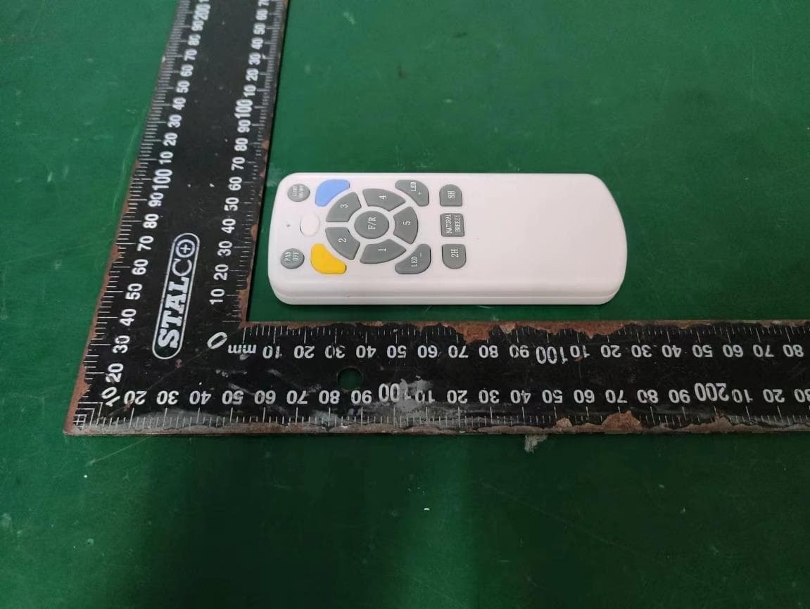
2AEBXET4379
Oct 24, 2023Remote Control
Equipment Class
DSC - Part 15 Security/Remote Control Transmitter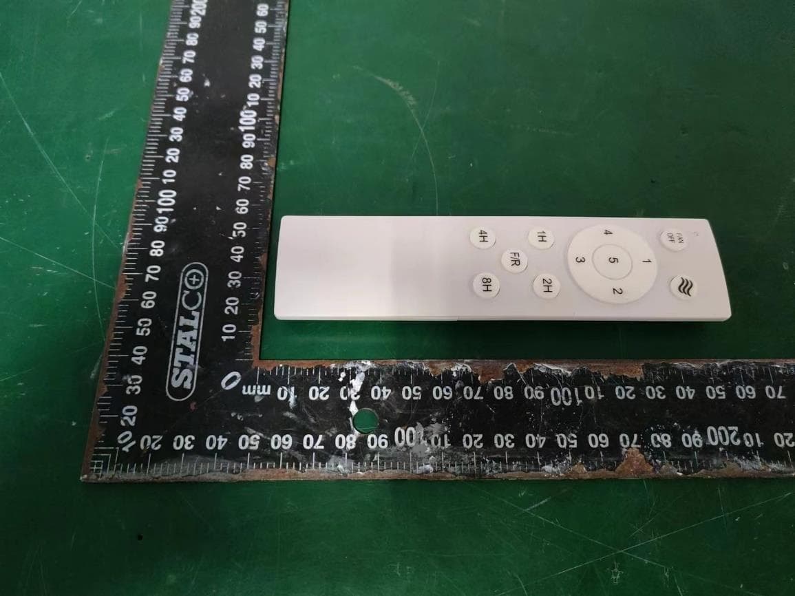
2AEBXET4470
Oct 24, 2023Remote Control
Equipment Class
DSC - Part 15 Security/Remote Control Transmitter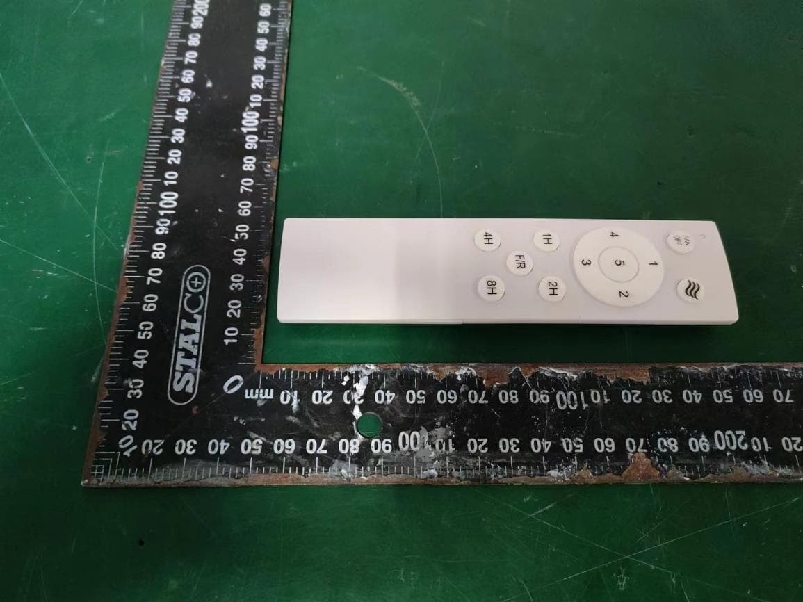
2AEBXET4437
Oct 24, 2023Remote Control
Equipment Class
DSC - Part 15 Security/Remote Control Transmitter
2AEBXRF-21-A
Jun 02, 2015Remote control
Equipment Class
DSC - Part 15 Security/Remote Control Transmitter