2AEBXET4379Remote Control
EGLO Hong Kong Lighting Ltd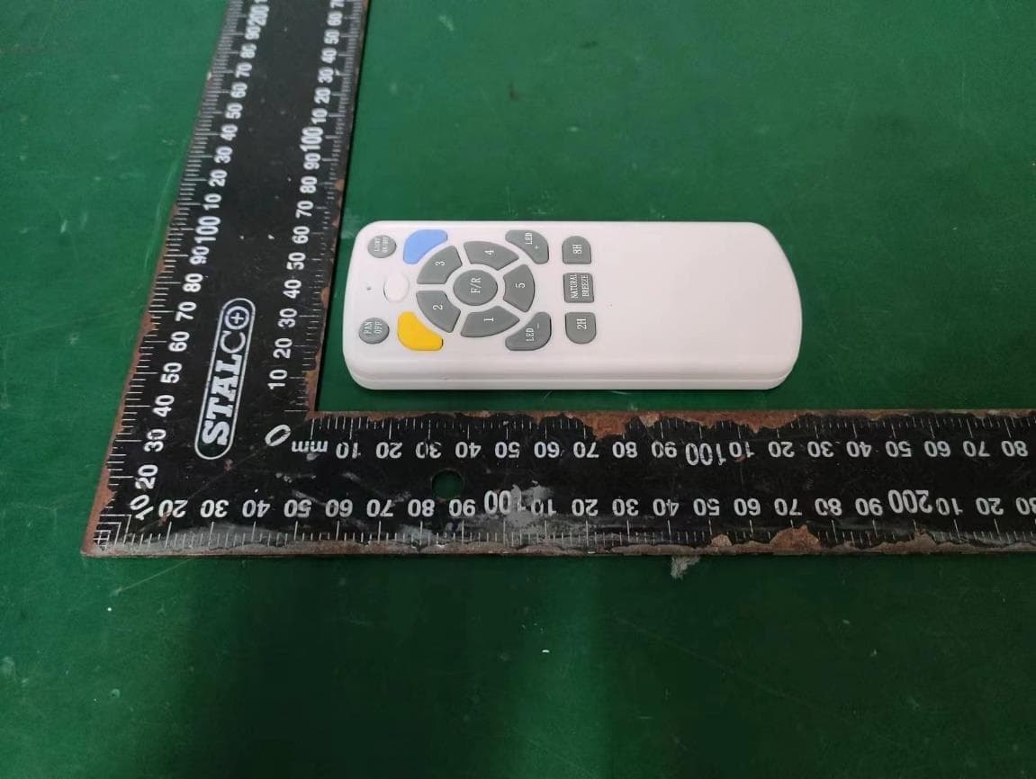
Click to zoom
Application Details
- Equipment Class
- DSC - Part 15 Security/Remote Control Transmitter
- Date of Grant
- Oct 24, 2023
- Application Purpose
- Original Equipment
- Date of Application
- Oct 24, 2023
- Equipment Note
- Remote Control
- Frequency Range
- 433.92000000 - 433.92000000
- Company
- EGLO Hong Kong Lighting Ltd
- Country
- China
Documents & Files
Document Text
Text extracted from the exhibit documents filed with the FCC. Open a document above to read the original.
Users Manual
Ceiling Fan Owner's Manual Read and Save These Instructions MODEL: SURFLINE Tools and Materials Required......................................................................................... Unpacking Your Fan ...................................................................................................... Safety Rules................................................................................................................... Mounting Options........................................................................................................... Hanging the Fan ............................................................................................................ Making Electrical Connections....................................................................................... Finishing the Installation................................................................................................. Attaching the Fan Blades............................................................................................... Operating Your Fan ..................................................................................................... Care of Your Fan........................................................................................................... Troubleshooting............................................................................................................ TABLE OF CONTENTS 1 1 2 3 4-5 6 7 8 9 10 10 Install the Light Kit ......................................................................................................... 8 1 a c d e f g 2. PACKAGE CONTENTS Unpack your fan and check the contents. You should have the following items: a. Blade set b. Hanger bracket c. Canopy and Cover d. Downrod assembly e. Housing f. Fan motor assembly h. Philips screw driver Blade screw driver 11 mm wrench Step ladder Wire cutters 1. TOOLS AND MATERIALS REQUIRED h g. Lamp shade (for with light model) 3) Remote Control (1) 3 10 1. To reduce the risk of electric shock, insure electricity has been turned off at the circuit breaker or fuse box before beginning. 2. All wiring must be in accordance with the National Electrical Code and local electrical codes. Electrical installation should be performed by a qualified licensed electrician. 3. WARNING: To reduce the risk of electrical shock and fire, do not use this fan with any solid-state fan speed control device. 4. WARNING: To reduce the risk of personal injury, use only the two steel screws (and lock washers) provided with the outlet box for mounting to the outlet box. Most outlet boxes commonly used for the support of lighting fixtures are not acceptable for fan support and may need to be replaced, consult a qualified electrician if in doubt. 5. The outlet box and support structure must be securely mounted and capable of reliably supporting a minimum of 50 pounds. Use only UL Listed outlet boxes marked "FOR FAN SUPPORT". 6. The fan must be mounted with a minimum of 7 feet clearance from the trailing edge of the blades to the floor. 7. Do not operate reversing switch while fan blades are in motion. Fan must be turned off and blades stopped before reversing blade direction. 8. Avoid placing objects in the path of the blades. 9. To avoid personal injury or damage to the fan and other items, be cautious when working around or cleaning the fan. 10. Do not use water or detergents when cleaning the fan or fan blades. A dry dust cloth or lightly dampened cloth will be suitable for most cleaning. 11. After marking electrical connections, spliced conductors should be turned upward and pushed carefully up into outlet box. The wires should be spread apart with the grounded conductor and the equipment-grounding conductor on one side of the outlet box. 12. Electrical diagrams are reference only. Light kit that are not packed with the fan must be UL Listed and marked suitable for use with the model fan you are installing. Switches must be UL General Use Switches. Refer to the Instructions packaged with the light kits and switches for proper assembly. 2 3. SAFETY RULES WARNING TO REDUCE THE RISK OF FIRE, ELECTRIC SHOCK OR PERSONAL INJURY, MOUNT FAN TO OUTLET BOX MARKED "ACCEPTABLE FOR FAN SUPPORT". WARNING TO REDUCE THE RISK OF PERSONAL INJURY, DO NOT BEND THE BLADE BRACKETS (ALSO REFERRED TO AS FLANGES) DURING ASSEMBLY OR AFTER INSTALLATION. DO NOT INSERT OBJECTS IN THE PATH OF THE BLADES. 3 4. MOUNTING OPTIONS If there isn't an existing UL listed mounting box, then read the following instructions. Disconnect the power by removing fuses or turning off circuit breakers. Secure the outlet box directly to the building structure. Use appropriate fasteners and building materials. The outlet box and its support must be able to fully support the moving weight of the fan (at least 50 lbs). Do not use plastic outlet boxes. Figures 1,2 and 3 are examples of different ways to mount the outlet box. Note: You may need a longer downrod to maintain proper blade clearance when installing on a steep, sloped ceiling. (Fig. 3) To hang your fan where there is an existing fixture but no ceiling joist, you may need an installation hanger bar as shown in Figure 4. Outlet box Outlet box Figure 1 Figure 3 Figure 4 Outlet box Figure 2 Provide strong support Recessed outlet box Ceiling mounting bracket Angled ceiling maximum 20 º 4 5. HANGING THE FAN REMEMBER to turn off the power. Follow the steps below to hang your fan properly. STANDARD CEILING INSTALLATION Step 1. Pass the 120-volt supply wires through the center hole in the ceiling hanger bracket as shown in Fig. 5. Step 2. Secure the hanger bracket to the ceiling outlet box with the screws and washers included with mounting hardware (Fig.5). Step 3. Remove the hanger pin, lock pin and set screws from the top of the motor assembly. Step 4. Route wires exiting from the top of the fan motor through the canopy, coupling cover and then through the ball/downrod. (Fig. 6) Step 5. Align the holes at the…
Text truncated - open the document above for the full version.
Users Manual
Ceiling Fan Owner's Manual Read and Save These Instructions MODEL: TIROL Tools and Materials Required......................................................................................... Unpacking Your Fan ...................................................................................................... Safety Rules................................................................................................................... Mounting Options........................................................................................................... Hanging the Fan ............................................................................................................ Making Electrical Connections....................................................................................... Finishing the Installation................................................................................................. Attaching the Fan Blades............................................................................................... Operating Your Fan ..................................................................................................... Care of Your Fan........................................................................................................... Troubleshooting............................................................................................................ TABLE OF CONTENTS 1 1 2 3 4-5 6 7 8 9 10 10 Install the Light Kit ......................................................................................................... 8 1 a c d e f g 2. PACKAGE CONTENTS Unpack your fan and check the contents. You should have the following items: a. Blade set b. Hanger bracket c. Canopy and Cover d. Downrod assembly e. Coupling cover f. Fan motor assembly h. Philips screw driver Blade screw driver 11 mm wrench Step ladder Wire cutters 1. TOOLS AND MATERIALS REQUIRED h g. Lamp shade (for with light model) Down cover (for no light model) 3) Remote Control (1) 3 10 1. To reduce the risk of electric shock, insure electricity has been turned off at the circuit breaker or fuse box before beginning. 2. All wiring must be in accordance with the National Electrical Code and local electrical codes. Electrical installation should be performed by a qualified licensed electrician. 3. WARNING: To reduce the risk of electrical shock and fire, do not use this fan with any solid-state fan speed control device. 4. WARNING: To reduce the risk of personal injury, use only the two steel screws (and lock washers) provided with the outlet box for mounting to the outlet box. Most outlet boxes commonly used for the support of lighting fixtures are not acceptable for fan support and may need to be replaced, consult a qualified electrician if in doubt. 5. The outlet box and support structure must be securely mounted and capable of reliably supporting a minimum of 50 pounds. Use only UL Listed outlet boxes marked "FOR FAN SUPPORT". 6. The fan must be mounted with a minimum of 7 feet clearance from the trailing edge of the blades to the floor. 7. Do not operate reversing switch while fan blades are in motion. Fan must be turned off and blades stopped before reversing blade direction. 8. Avoid placing objects in the path of the blades. 9. To avoid personal injury or damage to the fan and other items, be cautious when working around or cleaning the fan. 10. Do not use water or detergents when cleaning the fan or fan blades. A dry dust cloth or lightly dampened cloth will be suitable for most cleaning. 11. After marking electrical connections, spliced conductors should be turned upward and pushed carefully up into outlet box. The wires should be spread apart with the grounded conductor and the equipment-grounding conductor on one side of the outlet box. 12. Electrical diagrams are reference only. Light kit that are not packed with the fan must be UL Listed and marked suitable for use with the model fan you are installing. Switches must be UL General Use Switches. Refer to the Instructions packaged with the light kits and switches for proper assembly. 2 3. SAFETY RULES WARNING TO REDUCE THE RISK OF FIRE, ELECTRIC SHOCK OR PERSONAL INJURY, MOUNT FAN TO OUTLET BOX MARKED "ACCEPTABLE FOR FAN SUPPORT". WARNING TO REDUCE THE RISK OF PERSONAL INJURY, DO NOT BEND THE BLADE BRACKETS (ALSO REFERRED TO AS FLANGES) DURING ASSEMBLY OR AFTER INSTALLATION. DO NOT INSERT OBJECTS IN THE PATH OF THE BLADES. 3 4. MOUNTING OPTIONS If there isn't an existing UL listed mounting box, then read the following instructions. Disconnect the power by removing fuses or turning off circuit breakers. Secure the outlet box directly to the building structure. Use appropriate fasteners and building materials. The outlet box and its support must be able to fully support the moving weight of the fan (at least 50 lbs). Do not use plastic outlet boxes. Figures 1,2 and 3 are examples of different ways to mount the outlet box. Note: You may need a longer downrod to maintain proper blade clearance when installing on a steep, sloped ceiling. (Fig. 3) To hang your fan where there is an existing fixture but no ceiling joist, you may need an installation hanger bar as shown in Figure 4. Outlet box Outlet box Figure 1 Figure 3 Figure 4 Outlet box Figure 2 Provide strong support Recessed outlet box Ceiling mounting bracket Angled ceiling maximum 20 º 4 5. HANGING THE FAN REMEMBER to turn off the power. Follo w the steps below to hang your fan properly. STANDARD CEILING INSTALLATION Step 1. Pass the 120-volt supply wires through the center hole in the ceiling hanger bracket as shown in Fig. 5. Step 2. Secure the hanger bracket to the ceiling outlet box with the screws and washers included with mounting hardware (Fig.5). Step 3. Remove the hanger pin, lock pin and set screws from the top of the motor assembly. Step 4. Route wires exiting from the top of the fan motor through the canopy, coupling cover and then through the ball/downrod. (F…
Text truncated - open the document above for the full version.
Attestation Statements
EGLO Hong Kong Lighting Ltd Covered Equipment Certification Attestation Letter DATE Federal Communications Commission Authorization and Evaluation Division 7435 Oakland Mills Road Columbia, MD 21046 USA ATTN.: Reviewing Engineer FCC ID: 2AEBXET4379 EGLO Hong Kong Lighting Ltd (“the applicant”) certifies that the equipment for which authorization is sought is not “covered” equipment prohibited from receiving an equipment authorization pursuant to section 2.903 of the FCC rules. Note: If the equipment for which the applicant seeks authorization is produced by any of the entities identified on the current Covered List, the applicant should include an explanation on why the equipment is not “covered” equipment. <Signature> Name: Alex.Gu Title: engineer Company: EGLO Hong Kong Lighting Ltd
Attestation Statements
EGLO Hong Kong Lighting Ltd Covered Equipment Certification Attestation Letter DATE Federal Communications Commission Authorization and Evaluation Division 7435 Oakland Mills Road Columbia, MD 21046 USA ATTN.: Reviewing Engineer FCC ID: 2AEBXET4379 EGLO Hong Kong Lighting Ltd (“the applicant”) certifies that, as of the date of the filing of the application, the applicant is not identified on the Covered List as an entity producing “covered” equipment. <Signature> Name: Alex.Gu Title: engineer Company: EGLO Hong Kong Lighting Ltd
Cover Letter(s)
DATE : 2023.9.22 Federal Communications Commission Authorization & Evaluation Division 7345 Oakland Mills Road Columbia, Maryland 21046 Authority to Act as Agent On our behalf, I appoint EST Technology Co., Ltd. Address: Chilingxiang, Qishantou, Santun, Houjie, Dongguan, Guangdong, China (Name of Agent company name and address) to act as our agent in the preparation of this application for equipment certification. I certify that submitted documents properly describe the device or system for which equipment certification is sought. I also certify that each unit manufactured, imported or marketed, as defined in the Federal Communications Commission’s regulations will have affixed to it a label identical to that submitted for approval with this application. For instances where our authorized agent signs the application for certification on our behalf, I acknowledge that all responsibility for complying with the terms and conditions for certification, still resides with EGLO Hong Kong Lighting Ltd Address: Rm 1803, 18/F Multifield Centre, 426 Shanghai Street, Mongkok, Kowloon, Hong Kong, China (Applicant Name and address) <Signature> Name: Alex.Gu Title: engineer Company: EGLO Hong Kong Lighting Ltd
Cover Letter(s)
DATE : 2023.9.22 Equipment Autorisation Division Federal Communications Commission 7435 Oakland Mills Road Columbia, MD 21046 FCC ID: 2AEBXET4379 Product Name: Remote Control Request for Confidentiality Pursuant to Sections 0.457 and 0.459 of the commissions rules, we hereby request that the following documents be held confidential: (List here the documents for which you are seeking confidentiality – for example ...) •Schematics & Bom •Block diagram •Operation description These materials contain trade secrets and proprietary information and are not customarily released to the public. The public disclosure of this information might be harmful to the company and provide unjustified benefits to our competitors. <Signature> Name: Alex.Gu Title: engineer Company: EGLO Hong Kong Lighting Ltd
External Photos
External Photos M/N: ET4379 External Photos M/N: ET4379 External Photos M/N: ET4379
Internal Photos
Internal Photos M/N: ET4379 Internal Photos M/N: ET4379 Internal Photos M/N: ET4379
RF Exposure Info
FCC ID: 2AEBXET4379 EST Technology Co., Ltd Report No. ESTE-R2309014 Page 1 of 3 FCC RF EXPOSURE REPORT EGLO Hong Kong Lighting Ltd Remote control Model Number: ET4379 FCC ID: 2AEBXET4379 Applicant: EGLO Hong Kong Lighting Ltd Address: Rm 1803, 18/F Multifield Centre, 426 Shanghai Street, Mongkok, Kowloon, Hong Kong, China Prepared By: EST Technology Co., Ltd. Chilingxiang, Qishantou, Santun, Houjie, Dongguan, Guangdong, China Tel: 86-769-83081888-808 Report Number: ESTE-R2309014 Date of Test: Jul. 17~Sep. 05, 2023 Date of Report: Sep. 05, 2023 FCC ID: 2AEBXET4379 EST Technology Co., Ltd Report No. ESTE-R2309014 Page 2 of 3 1. Applicable Standards FCC Part 2(Section 2.1093) FCC KDB 447498 D04 Interim General RF Exposure Guidance v01 2. Exposure Evaluation of Portable or Mobile Devices Human exposure to RF emissions from portable devices (47 CFR §2.1093), as defined by the FCC, must be evaluated with respect to the FCC-adopted limits for SAR. Evaluation of mobile devices, as defined by the FCC, may also be performed with respect to SAR limits, but in such cases it is usually simpler and more cost-effective to evaluate compliance with respect to field strength or power density limits. For certain devices that are designed to be used in both mobile and portable configurations similar to those described in 47 CFR §2.1091(d)(4), such as certain desktop phones and wireless modem modules, compliance for mobile configurations is also satisfied when the same device is evaluated for SAR compliance in portable configurations. The test exclusions are applicable only when the minimum test separation distance is ≤ 50 mm and for transmission frequencies between 300 MHz and 6 GHz. When the minimum test separation distance is < 5 mm, a distance of 5 mm is applied to determine SAR test exclusion. FCC ID: 2AEBXET4379 EST Technology Co., Ltd Report No. ESTE-R2309014 Page 3 of 3 3. Evaluation Results Ant gain=3dBi Ant numeric gain=1.99 Field strength = 84.02dBuV/m@3m Limited=2040*f*(0.5/20)^x, x=-log(60/(2040*f*√f))= 23.17mW EIRP={ [10 (84.02 /20) /10 6 *3] 2 / (30*1 }*1000mW =0.0757mW < 23.17mW Note: 1. We choose f=0.43392GHz to calculate MPE limit as higher frequency will have lower MPE limits. 2. SAR Test Exclusion Thresholds is 23.17mW for separation distance 5mm. Therefore, SAR test is not required. End of Test Report
Test Report
FCC ID: 2AEBXET4379 EST Technology Co., Ltd Report No. ESTE-R2309013 Page 1 of 41 FCC PART 15C TEST REPORT FOR CERTIFICATION On Behalf of EGLO Hong Kong Lighting Ltd Remote control Model Number: ET4379 FCC ID: 2AEBXET4379 Applicant: EGLO Hong Kong Lighting Ltd Address: Rm 1803, 18/F Multifield Centre, 426 Shanghai Street, Mongkok, Kowloon, Hong Kong, China Prepared By: EST Technology Co., Ltd. Chilingxiang, Qishantou, Santun, Houjie, Dongguan, Guangdong, China Tel: 86-769-83081888-808 Report Number: ESTE-R2309013 Date of Test: Jul. 17~Sep. 05, 2023 Date of Report: Sep. 22, 2023 FCC ID: 2AEBXET4379 EST Technology Co., Ltd Report No. ESTE-R2309013 Page 2 of 41 TABLE OF CONTENTS Description Page TEST REPORT VERIFICATION......................................................................................................................... 3 1. GENERAL INFORMATION ................................................................................................................. 5 1.1. Description of Device (EUT) ........................................................................................................... 5 1.2. Antenna Information ........................................................................................................................ 5 1.3. Information of RF Cable .................................................................................................................. 5 2. SUMMARY OF TEST ......................................................................................................................... 6 2.1. Summary of test result ...................................................................................................................... 6 2.2. Test Facilities ................................................................................................................................... 7 2.3. Measurement uncertainty ................................................................................................................. 8 2.4. Assistant equipment used for test ..................................................................................................... 8 2.5. Block Diagram ................................................................................................................................. 8 2.6. Test Mode ......................................................................................................................................... 9 2.7. Channel List ..................................................................................................................................... 9 2.8. Test Equipment List ....................................................................................................................... 10 3. DUTY CYCLE ................................................................................................................................ 12 3.1. Limit ............................................................................................................................................... 12 3.2. Test Setup ....................................................................................................................................... 12 3.3. Spectrum Analyzer Setting ............................................................................................................. 12 3.4. Test Procedure ................................................................................................................................ 12 3.5. Test Conditions ............................................................................................................................... 13 3.6. Test Result ...................................................................................................................................... 13 4. FIELD STRENGTH OF FUNDAMENTAL ............................................................................................ 15 4.1. Limit ............................................................................................................................................... 15 4.2. Test Setup ....................................................................................................................................... 16 4.3. Spectrum Analyzer Setting ............................................................................................................. 16 4.4. Test Procedure ................................................................................................................................ 16 4.5. Test Result ...................................................................................................................................... 17 5. RADIATED SPURIOUS EMISSIONS .................................................................................................. 20 5.1. Limit ............................................................................................................................................... 20 5.2. Test Setup ....................................................................................................................................... 22 5.3. Spectrum Analyzer Setting ............................................................................................................. 23 5.4. Test Procedure ................................................................................................................................ 24 5.5. Test Result ...................................................................................................................................... 25 6. 20DB BANDWIDTH ........................................................................................................................ 30 6.1. Limit ............................................................................................................................................... 30 6.2. Test Setup ...............................................................…
Text truncated - open the document above for the full version.
Test Report
Free: 433.92MHz Ant gain: 3dBi Modu lation: ASK KEY number: 19 standby current: 3V Antenna manufacturer: The antenna is laid out on the PCB board. PCB manufacturer information: 1. JIANG MEN CHANG MING PCB Factory BEI TOU ZUI INDUSTRIAL ZONE LI LE TOWN, LI YI RD.JIANG HAI JIANGMEN, Guangdong Sheng 529060 China model: CM-2 2. ZHUHAI JIE SUN PRICION PCB CO LTD NO 210 ANJI EAST RD CHAOTANWAN SANZAO TOWN JINWAN DISTRICT ZHUHAI, Guangdong Sheng 519040 China model:JS
Test Setup Photos
Radiated Test (Below 1GHz) Radiated Test (Above 1GHz)
Contact Information
Applicant
Alex Gu(Engineer)
Test Firm
EST Technology Co., Ltd.Iceman Hu
[email protected]+86 0769-83081888
Technical Specifications
| # | Rule Parts | Frequency Range | Power Output |
|---|---|---|---|
| 1 | 15.231 | 433.92 MHz - 433.92 MHz | - |
Other Applications from EGLO Hong Kong Lighting Ltd
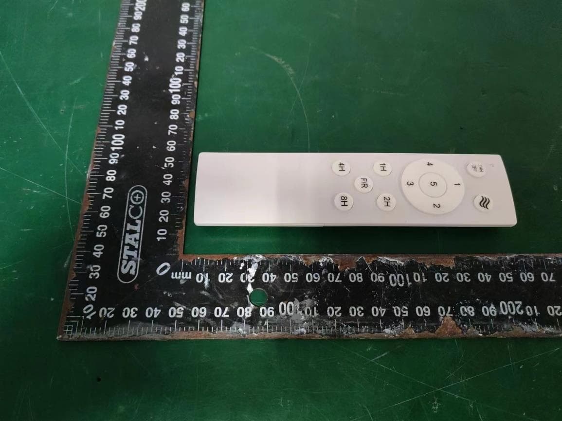
2AEBXET4470
Oct 24, 2023Remote Control
Equipment Class
DSC - Part 15 Security/Remote Control Transmitter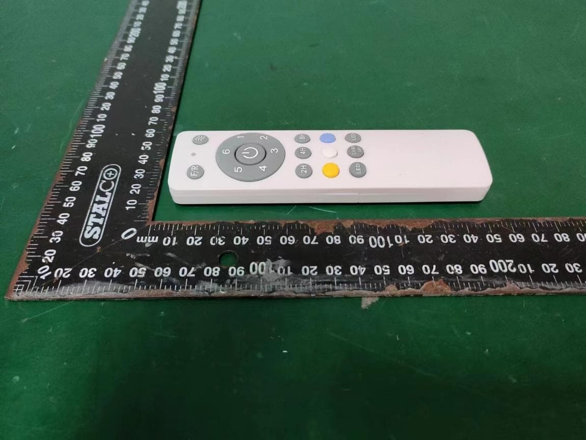
2AEBXET4271
Oct 24, 2023Remote Control
Equipment Class
DSC - Part 15 Security/Remote Control Transmitter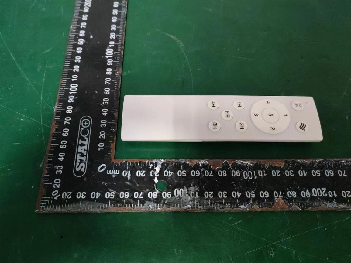
2AEBXET4437
Oct 24, 2023Remote Control
Equipment Class
DSC - Part 15 Security/Remote Control Transmitter
2AEBXRF-21-A
Jun 02, 2015Remote control
Equipment Class
DSC - Part 15 Security/Remote Control Transmitter