2AEEDUS-SC201Smart Surveillance Camera
Xiamen Tongren IOT Technology Co.,Ltd.Application Details
- Equipment Class
- DTS - Digital Transmission System
- Date of Grant
- May 11, 2015
- Application Purpose
- Original Equipment
- Date of Application
- May 11, 2015
- Equipment Note
- Smart Surveillance Camera
- Frequency Range
- 2412.00000000 - 2462.00000000
- Country
- China
Documents & Files
Document Text
Text extracted from the exhibit documents filed with the FCC. Open a document above to read the original.
Users Manual
Smart Surveillance Camera – Manual Product Name: SmartHome – Wireless Smart Surveillance Camera Product Description: This product is a key part in the USUNG SmartHome Safeguarding & Surveillance System, and it may transmit local live video to USUNG SmartHome Controlling Client Software through LAN or Internet, as allows the user to view live surveillance scene through their mobile phone at any time. Moreover, this product also comes up with wireless data link module, which allows you install these cameras in your home wherever power supply is available without consideration of network cabling. Installation: Before the hardware installation, please refer to and follow the method introduced in the“Software Usage & Settings”section of the “Home Safeguarding & Surveillance Suite Initial Setup & Usage Guide” to add the surveillance camera to your home wireless network, and thereafter, to proceed with the fixing and installation. 1)Ceiling Installation • Drill two holes for screws at proper positions on the bottom plate; • Insert the larger screws through the bottom plate and use them to fix the bottom plate to the ceiling; • Align the two holes in the camera bottom to the holes on the bottom plate, lock and tighten them up. 2)Wall Installation • Fix the iron plate to the bottom plate by fastening two smaller screws into the smaller screw holes on the bottom plate. • Drill two holes at proper positions in the wall with a 6mm drill bit, and insert the screw sleeves, and fasten both larger screws through the two side holes on the iron plate. • Align the two holes in the camera bottom to the holes on the bottom plate, lock and tighten them up. Connect to Network Wired Connection: Connect one of the RJ45 jacks of a Twisted Pair Cable (Network Cable) to the Ethernet interface on the rear of the camera, and another to a router or a switch(note that twisted pair cable usually cannot exceed 100 meters, otherwise may lead to unstable communication or connection failure. For distance exceeding 100 meters, a switch is recommended as relay; Wireless connection: using home WIFI network to establish data connections( for wireless configuration for the Surveillance Camera, please refer to “USUNG Home Safeguarding & Surveillance Suite Initial Setup and Usage Guide” for details. Power‐on Connect the power cable jack to the camera and the power adapter to a power source outlet. Do please use the original in‐package power adapter, otherwise may possibly cause hardware damage. Check the Network Indicator After power on, the camera starts to work, under normal case, the green light on the back of the Surveillance Camera will be steadily on, and the yellow light will be flashing. Interface Description: Adjustable Lens: Slightly rotate the lens clockwisely or counterclockwisely, until you get the clearest view. Rotate the camera: through the mobile client software, you may control to rotate the camera, for details please refer to “Home Safeguarding & Surveillance Suite Initial Setup & Usage Guide” Monitor through a smartphone: this device support apple iPhone and smartphone with Android system. As soon as the user installs the USUNG Home Safeguarding & Surveillance Client Software, and configures the Surveillance Camera properly by followingthe “Home Safeguarding & Surveillance Suite Initial Setup & Usage Guide” that is included in the product package, he/ she may monitor live surveillance scenes through the cameras from his/her smartphone. Precautions: 1. Please do not disassemble or try to repair the product in your own will; 2. Please do not put the product under extreme conditions like high temperature or high pressure , etc.; 3. Please keep the product away from baby or child; 4. Please keep the product dry and away from humidity; Xiamen Tongren IOT Technology Co.,Ltd. 24Hr hotline service:4008888022 Website:http://home.iusung.com Usung Home Safeguarder Manual Firstly, please download and install appropriate version of our client software from:http://home.iusung.com/en Secondly, you need to connect the camera to your LAN with a cable. Open the client software, please sign-up for a USUNG account, and log in. You may set a Sync Code during the sign-up process so that other family members may take advantage of the existing configuration. Please Add the Camera after login. You may add camera(s): 1.by inputting device ID 2.by scanning the camera barcode from your mobile (Device ID and barcode are printed on label at the bottom of the camera) 3.by searching – automatically search and add cameras in the LAN. 4.by adding from shared accounts. (Enter the Sync Code set in the sign-up process for a USUNG Account, once signed-in you may acquire shared camera information under this account.) Lastly, input the password for the camera itself (default no password), click on the “Done ” button to finish adding. The camera will be shown in the main interface, click to view the monitor screen, and click the Gear Button in the right side to configure the camera. You may click on the Edit Button at the top right corner to modify camera information such as name, access code etc., or delete camera. Operations that you can perform in the monitor view interface: Horizontal/vertical mirror view, cradle head auto-rotation, live sound, rotation lock, photographs, video, watch mode settings and exit. In the Camera Settings interface You can set the camera to connect to your home LAN through WIFI; You can set an independent password for the camera; Alarm & push message settings and TF card settings for video storage. By touching navigation icons at the bottom, you may view alarm history, snapshots, and video information at any time; In Settings you may configure your USUNG Account; In Settings interface, you may set to share your cameras, and only those shared cameras can be synchronized to other mobile with a Sync Code. You may insert a TF card at the back of the camera, then the camera may start recording videos automatically. You may vie…
Text truncated - open the document above for the full version.
Cover Letter(s)
Xiamen Tongren IOT Technology Co.,Ltd 4F-A, Block A, Huaxun Buliding, Software Park, Torch Hi-tech Zone, Xiamen, China FCC Agent Authorisation Template 22-01-2015 TUV SUD BABT TCB Octagon House, Segensworth Road, Fareham, Hampshire, PO15 5RL Dear Sir or Madam, We, (Xiamen Tongren IOT Technology Co.,Ltd.; 4F-A, Block A, Huaxun Buliding, Software Park, Torch Hi-tech Zone, Xiamen, China), hereby authorize (Shenzhen Microtest Technology Co.,Ltd;Lisa Li) to act as our agent in all matters relating to applications for equipment authorization, including the signing of all documents relating to these matters. This authorization expires on (Jan. 22, 2016). Sincerely, Company Officer: Telephone Number: 0592-3929702 Email: [email protected] FCC Agent Authorisation
Cover Letter(s)
Xiamen Tongren IOT Technology Co.,Ltd 4F-A, Block A, Huaxun Buliding, Software Park, Torch Hi-tech Zone, Xiamen, China FCC Confidentiality Template 22-01-2015 TUV SUD BABT TCB Octagon House, Segensworth Road, Fareham, Hampshire, PO15 5RL Confidentiality Request FCC ID: 2AD3CUS-SC201 Pursuant to Sections 0.457(d)(1)(ii) and 0.459 of the Commission’s Rules, (Xiamen Tongren IOT Technology Co.,Ltd.) hereby requests permanent confidential treatment of information accompanying this application as outlined below: - Block Diagram - Schematics - Operational Description (Xiamen Tongren IOT Technology Co.,Ltd) also hereby requests short-term confidential treatment of information accompanying this application as outlined below for a period of (up to 180) days: -Internal Photos -External Photos -User Manual -Test Set-up Photographs The above materials contain trade secrets and proprietary information not customarily released to the public. The public disclosure of these matters might be harmful to the Applicant and provide unjustified benefits to its competitors. The Applicant understands that pursuant to Rule 0.457(d)(1)(ii), disclosure of this Application and all accompanying materials will not be made before the date of the Grant for this Application. Yours sincerely, Company Officer: Telephone Number: 0592-3929702 Email: [email protected] FCC Confidentiality FCC ID: 2AE E DUS-SC201
External Photos
APPENDIX-PHOTOGRAPHS OF EUT CONSTRUCTIONAL DETAILS Photo 1 Photo 2 Photo 3 Photo 4 Photo 5 Photo 6 Photo 7 Photo 8 Photo 9 Photo 10
ID Label/Location Info
4.5*2.0cm Xiamen Tongren IOT Technology Co.,Ltd. Model: US‐SC201 FCC ID: 2AD3CUS‐SC201
Internal Photos
Photo 11 Photo 12 Photo 13 Photo 14 Photo 15 Photo 16 Photo 17 Photo 18 Photo 19 Photo 20
RF Exposure Info
RF EXPOSURE TEST FCC ID: 2AD3CUS-SC201 Applied procedures / limit These devices are not exempted from compliance does not exceed the Commission’s RF exposure guidelines.Unless a device operates at substantially low power levels,with a low gain antenna(s),supporting information is generally needed to establish the various potential operating configurations and exposure conditions of a transmitter and its antenna(s) in order to determine compliance with the RF exposure guidelines. In order to demonstrate compliance with MPE requirement(see Section 2.1091),the following information is typically needed: Calculation that estimates the minimum separation distance(20 cm or more)between an antenna and persons required to satisfy power density limits defined for free space. Antenna installation and device operating instructions for installers(professional/unskilled users),and the parties responsible for ensuring compliance with the RF exposure requirement Any caution statements and/or warming labels that are necessary in order to comply with the exposure limits Any other RF exposure related issues that may affect MPE compliance. FCC 1.1310: The criteria listed in the following table shall be used to evaluate the environmental impact of human exposure to radio-frequency(RF) radiation as specified in 1.1307(b). (A) Limits for Occupational / Controlled Exposure Frequency Range (MHz) Electric Field Strength (E) (V/m) Magnetic Field Strength (H) (A/m) Power Density (S) (mW/ cm 2 ) Averaging Time |E| 2 ,|H| 2 or S (minutes) 0.3-3.0 614 1.63 (100)* 6 3.0-30 1842 / f 4.89 / f (900 / f)* 6 30-300 61.4 0.163 1.0 6 300-1500 F/300 6 1500-100,000 5 6 (B) Limits for General Population / Uncontrolled Exposure Frequency Range (MHz) Electric Field Strength (E) (V/m) Magnetic Field Strength (H) (A/m) Power Density (S) (mW/ cm 2 ) Averaging Time |E| 2 ,|H| 2 or S (minutes) 0.3-1.34 614 1.63 (100)* 30 1.34-30 824/f 2.19/f (180/f)* 30 30-300 27.5 0.073 0.2 30 300-1500 F/1500 30 1500-100,000 1.0 30 Note: f = frequency in MHz ; *Plane-wave equivalent power density MPE CALCULATION METHOD Calculation Method of RF Safety Distance: P :power input to the antenna in Mw EIRP :Equivalent(effective) isotropic radiated power. S :power density mW/ cm 2 G ;numeric gain of antenna relative to isotropic radiator R :distance to centre of radiation in cm FCC radio frequency exposure limits may be exceeded at distances closer than r cm from the antenna of this device EIRP=10 ( Antenna Gain+Peak Output Power/10) Note: 1. s=1.0 mW /cm 2 for limits for General Population/Uncontrolled Exposures. 2. The time averaged power over 30 minutes will be equaled Output Power. 3. The Power Density at a distance of 20cm calculated from the formula is far below the limit of 1MW/ cm 2 TEST RESULTS NOTE: (For mobile or fixed location transmitters, the maximum power density is 1.0mW/cm 2 even if the calculation indicates that the power density would be larger) PK output power (MAX) (dBm) Output power to antenna (mW) Antenna Gain (numeric) Power Density (S) (mW/ cm 2 ) Limit of Power Density (S) (mW/ cm 2 ) Result 17.87 61.23 1.995(3dbi) 0.024 1 Pass
Test Report
FCC Part 15C Measurement And Test Report For Xiamen To n g r e n IOT Technology Co.,Ltd. 4F-A, Block A, Huaxun Buliding, Software Park, Torch Hi-tech Zone, Xiamen, China. FCC ID: 2AD3CUS-SC201 Jan. 17, 2015 This Report Concerns: Original Report Equipment Type: Smart Surveillance Camera Report Number: MTI141204005RF Test Engineer: Bill Chen Reviewed By: Jason Zheng Approved & Authorized By: Hebe Lee Test Date: Jan. 05 - Jan. 17, 2015 Prepared By: Shenzhen Microtest Technology Co.,Ltd 6F, Zhongbao Building, Gushu, Bao' an District, Shenzhen, P.R.China Tel: +86-755-8885 0135 Fax: +86-755-8885 0136 Note: This test report is limited to the above client company and the product model only. It may not be duplicated without prior written consent of Shenzhen Microtest Technology Co.,Ltd. Report No.:MTI141204005RF Page 2 of 48 TEST RESULT CERTIFICATION Applicant’s name ................. : Xiamen Tongren IOT Technology Co.,Ltd. Address .................................. : 4F-A, Block A, Huaxun Buliding, Software Park, Torch Hi-tech Zone, Xiamen, China. Manufacture's Name ............ : Xiamen Tongren IOT Technology Co.,Ltd. Address .................................. : 4F-A, Block A, Huaxun Buliding, Software Park, Torch Hi-tech Zone, Xiamen, China. Product description Product name ............................: Smart Surveillance Camera Model and/or type reference : US-SC201 Serial Model ...............................: N/A Standards .............................. : FCC Part15.247 Test procedure .............................ANSI C63.4-2003 Report No.:MTI141204005RF Page 3 of 48 Table of Contents Page 1 . SUMMARY OF TEST RESULTS 5 1.1 TEST FACILITY 6 1.2 MEASUREMENT UNCERTAINTY 6 2 . GENERAL INFORMATION 7 2.1 GENERAL DESCRIPTION OF EUT 7 2.2 DESCRIPTION OF TEST MODES 9 2.3 BLOCK DIGRAM SHOWING THE CONFIGURATION OF SYSTEM TESTED 10 2.4 DESCRIPTION OF SUPPORT UNITS(CONDUCTED MODE) 11 2.5 EQUIPMENTS LIST FOR ALL TEST ITEMS 12 3 . EMC EMISSION TEST 13 3.1 CONDUCTED EMISSION MEASUREMENT 13 3.1.1 POWER LINE CONDUCTED EMISSION LIMITS 13 3.1.2 TEST PROCEDURE 14 3.1.3 DEVIATION FROM TEST STANDARD 14 3.1.4 TEST SETUP 14 3.1.5 EUT OPERATING CONDITIONS 14 3.1.6 TEST RESULTS 15 3.2 RADIATED EMISSION MEASUREMENT 17 3.2.1 RADIATED EMISSION LIMITS 17 3.2.2 TEST PROCEDURE 17 3.2.3 DEVIATION FROM TEST STANDARD 18 3.2.4 TEST SETUP 19 3.2.5 EUT OPERATING CONDITIONS 20 3.2.6 TEST RESULTS (BETWEEN 9KHZ – 30 MHZ) 21 3.2.7 TEST RESULTS (BETWEEN 30MHZ – 1GHZ) 22 3.2.8 TEST RESULTS (ABOVE 1000 MHZ) 23 4 . POWER SPECTRAL DENSITY TEST 32 4.1 APPLIED PROCEDURES / LIMIT 32 4.1.1 TEST PROCEDURE 32 4.1.2 DEVIATION FROM STANDARD 32 4.1.3 TEST SETUP 32 4.1.4 EUT OPERATION CONDITIONS 32 4.1.5 TEST RESULTS 33 5 . BANDWIDTH TEST 37 5.1 APPLIED PROCEDURES / LIMIT 37 5.1.1 TEST PROCEDURE 37 5.1.2 DEVIATION FROM STANDARD 37 Report No.:MTI141204005RF Page 4 of 48 Table of Contents Page 5.1.3 TEST SETUP 37 5.1.4 EUT OPERATION CONDITIONS 37 5.1.5 TEST RESULTS 38 6 . PEAK OUTPUT POWER TEST 42 6.1 APPLIED PROCEDURES / LIMIT 42 6.1.1 TEST PROCEDURE 42 6.1.2 DEVIATION FROM STANDARD 42 6.1.3 TEST SETUP 42 6.1.4 EUT OPERATION CONDITIONS 42 6.1.5 TEST RESULTS 43 7 . 100 KHZ BANDWIDTH OF FREQUENCY BAND EDGE 44 7.1 DEVIATION FROM STANDARD 44 7.2 TEST SETUP 44 7.3 EUT OPERATION CONDITIONS 44 7.4 TEST RESULTS 45 8 . ANTENNA REQUIREMENT 48 8.1 STANDARD REQUIREMENT 48 8.2 EUT ANTENNA 48 Report No.:MTI141204005RF Page 5 of 48 1. SUMMARY OF TEST RESULTS Test procedures according to the technical standards: FCC Part15 (15.247) , Subpart C Standard Section Test Item Judgment Remark 15.207 Conducted Emission PASS 15.247 (a)(2) 6dB Bandwidth PASS 15.247 (b) Peak Output Power PASS 15.247 (c) Radiated Spurious Emission PASS 15.247 (d) Power Spectral Density PASS 15.205 Band Edge Emission PASS 15.203 Antenna Requirement PASS NOTE: (1)” N/A” denotes test is not applicable in this Test Report Report No.:MTI141204005RF Page 6 of 48 1.1 TEST FACILITY Shenzhen Toby Technology Co., Ltd. Add.: 10/F.,A Block,Jiada R&D Bldg.,No.5 Songpingshan, Road, Science&Technology Park, Shenzhen, 518057 FCC Registration No.:811562 1.2 MEASUREMENT UNCERTAINTY The reported uncertainty of measurement y ± U,where expended uncertainty U is based on a standard uncertainty multiplied by a coverage factor of k=2,providing a level of confidence of approximately 95 %。 No. Item Uncertainty 1 Conducted Emission Test ±1.38dB 2 RF power,conducted ±0.16dB 3 Spurious emissions,conducted ±0.21dB 4 All emissions,radiated(<1G) ±4.68dB 5 All emissions,radiated(>1G) ±4.89dB 6 Temperature ±0.5°C 7 Humidity ±2% Report No.:MTI141204005RF Page 7 of 48 2. GENERAL INFORMATION 2.1 GENERAL DESCRIPTION OF EUT Equipment Smart Surveillance Camera Trade Name USUNG Model Name US-SC201 Serial Model N/A Model Difference N/A Product Description The EUT is a Smart Surveillance Camera Operation Frequency: 802.11b/g:2412~2462 MHz Modulation Type: 11g: BPSK, QPSK, 16QAM, 64QAM, OFDM 11b: DQPSK, DBPSK, DSSS, CCK Bit Rate of Transmitter 802.11b:11/5.5/2/1 Mbps 802.11g:54/48/36/24/18/12/9/6Mbps Number Of Channel 802.11b/g:11CH Antenna Designation: Please see Note 3. Output Power(Conducted): 802.11b: 17.87 dBm (Max.) 802.11g: 15.78 dBm (Max.) Antenna Gain (dBi) 2.1dbi Based on the application, features, or specification exhibited in User's Manual, the EUT is considered as an ITE/Computing Device. More details of EUT technical specification, please refer to the User's Manual. Channel List Please refer to the Note 2. Adapter Model:YJT-0520 AC Power Input: 100-240VAC, 0.3A, 50/60Hz Output: 5.0V 2000mA Battery N/A Connecting I/O Port(s) Please refer to the User's Manual Note: 1. For a more detailed features description, please refer to the manufacturer’s specifications or the User's Manual. 2. Channel List for 802.11b/g Channel Frequency (MHz) Channel Frequency (MHz) Channel Frequency (MHz) Channel Frequency (MHz) 01 2412 04 2427 07 2442 10 2457 02 2417 05 2432 08 2447 11 2462 03 2422 06 2437 09 2452 Report No.:MTI141204005RF Page 8 o…
Text truncated - open the document above for the full version.
Test Setup Photos
Report No.:MTI141204005RF Page 49 of 50 9. EUT TEST PHOTO Radiated Measurement Photos Report No.:MTI141204005RF Page 50 of 50 CONDUCTED EMISSION Photos
Contact Information
Applicant
Minghui Wang(Manager)
Test Firm
Shenzhen Microtest Technology Co.,Ltd.TOM XUE
Technical Specifications
| # | Rule Parts | Frequency Range | Power Output |
|---|---|---|---|
| 1 | 15C | 2.41 GHz - 2.46 GHz | 61.20 mW |
Other Applications from Xiamen Tongren IOT Technology Co.,Ltd.
2AEEDUS-G101
May 11, 2015Smart Gateway
Equipment Class
DTS - Digital Transmission System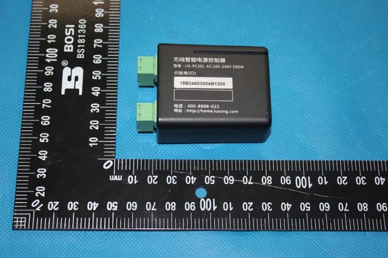
2AEEDUS-PC201
Apr 19, 2015Smart Power Controller
Equipment Class
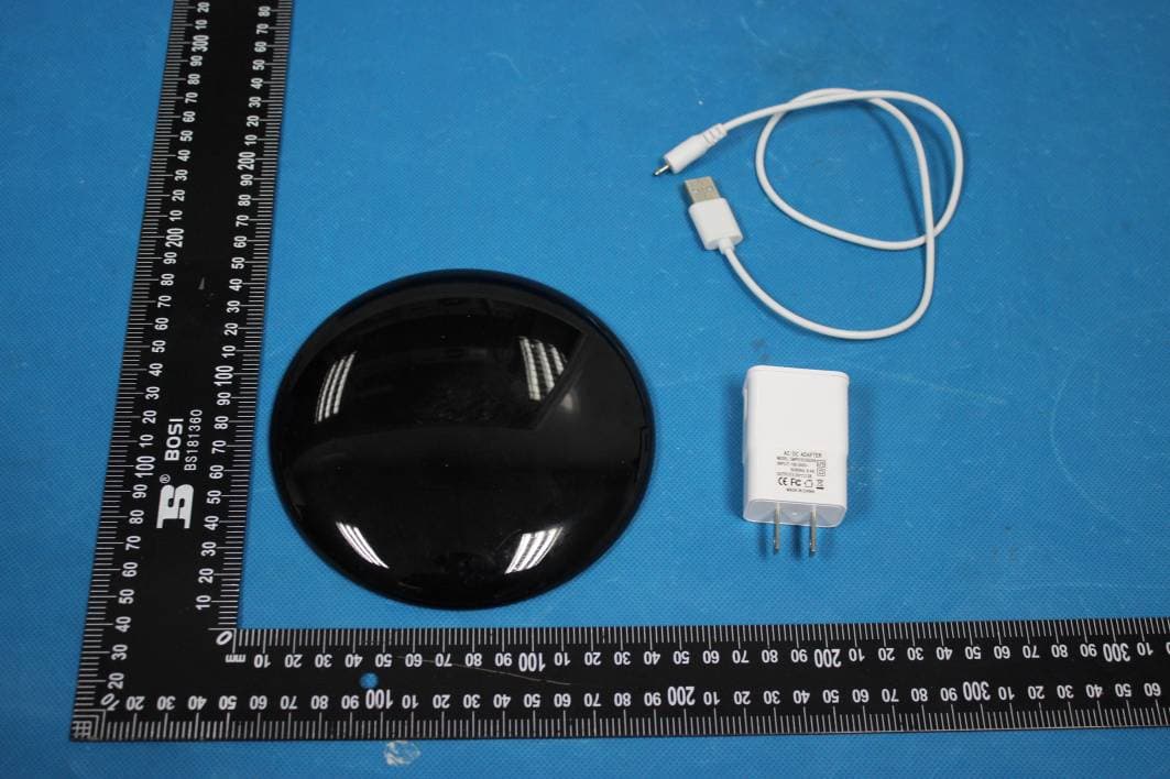
DXX - Part 15 Low Power Communication Device Transmitter2AEEDUS-IC101
Apr 19, 2015Smart IR Controller
Equipment Class
DXX - Part 15 Low Power Communication Device Transmitter2AEEDUS-SP101
Apr 19, 2015Smart Switch Panel
Equipment Class
DXX - Part 15 Low Power Communication Device Transmitter