2AEKF-LTS21LTS21 Multifunction Sports Headphones
LIVALL Tech Co., Ltd.
Click to zoom
Application Details
- Equipment Class
- DSS - Part 15 Spread Spectrum Transmitter
- Date of Grant
- Jun 07, 2022
- Application Purpose
- Original Equipment
- Date of Application
- Jun 07, 2022
- Equipment Note
- LTS21 Multifunction Sports Headphones
- Frequency Range
- 2402.00000000 - 2480.00000000
- Company
- LIVALL Tech Co., Ltd.
- Country
- China
Documents & Files
Document Text
Text extracted from the exhibit documents filed with the FCC. Open a document above to read the original.
Users Manual
www.livall.com LTS21 Multi-Functional Sports Headphones 1 1. Introduction Charging indicatorAir holeTouch button Charging contacts Mortise-tenon structure Microphone 2Microphone 1 Speaker hole 2. Packing list LIVALL TWS multifunctional sports headphones *1 Charging box *1 Head hanging bracket *1 Helmet bracket *1 Type-C charging cable *1 Traveling bag *1 Manual *1 Spare 3M glue *4 When opening the package to use it for the first time, please tear off the insulation film on the charging contacts, then plug in the charging cable, and charge it for 10 minutes to activate the Headphones. (The Headphones are in transport mode after leaving the factory. In this mode, they can standby for 12 months, and need to be charged for activation before use) 3. Instructions for use Begin to use Welcome to use LIVALL TWS multifunctional sports headphone, this manual will guide you how to use this product better. With the continuous improvement of the company's products, this manual will be updated from time to time. Also you can get the latest version and learn more information about headphones on LIVALL's official website (www.livall.com). Photo-shooting Direction-up Direction-Left Direction-down Intercom Direction-Right Confirm 2 FunctionLeft HeadphonesRight HeadphonesBling remote controller (when equipped) Power onLong press for 3 secondsPress any key Play / PauseTap twiceClick the "Confirm” key Previous songLong press for 2 secondsLong press the "up” arrow key Next songLong press for 2 secondsLong press the "down” arrow key Answer/hang upTap twiceClick the "Confirm” key (incoming call) RefuseLong press for 2 seconds/ Voice assistantTap three timesPress the "Intercom” key 1. Headphones off: Due to the large contact area of the Headphones keys, in order to avoid accidental contact, the Headphones body does not have the power off function. If you need to power off the Headphones, please remove the Headphones and put it in the charging box. 2.Electric quantity display: The Headphones is placed in the charging box, the charging box power is less than 20%, the read is always one for 2S, when the charging box power is more than 20%, the white is always on for 2S. 3.Clear headphone pairing records: With the charging box is open and the Headphones is in the warehouse, press the button on the back of the charging box for 15 seconds, then the red and white will alternate for 3 to 15 seconds, and the red light will blink for 5 seconds after 15 seconds. Charging box function Headhang mode: According to the figure, place the logo outward, align the connector of the R/L logo on the headhang bracket with the connector of the R/L logo on the Headphones, push it in, and fasten it tightly. Wear the headhang Headphones on the ear, adjust the comfortable position, and then use it. Assemble/wear headphones 3 Helmet mode: 1. With the logo facing outward, align the connector of the R/L logo of the Helmet bracket with the R/L logo of the Headphones, push it in, and fasten it tightly.2. Wear the helmet that requires Headphones; 3. Tear off the Spare 3M glue of the helmet bracket, put the Headphones in the comfortable position of the ear as shown in the picture, attach the helmet bracket, press and stand for 24 hours;Due to the different ear position of each person, the installation position of helmet bracket is different. If the helmet user is changed, the position of Helmet bracket needs to be adjusted again. 1.Opening the charging case, take out the Headphones and touch the Headphones LOGO until the indicator blinks quickly to enter the pairing mode. 2. Open the Bluetooth list of the mobile phone and find "LIVALL LTS21" to connect. 3. Press any key to activate and pair the Headphones with the flash control. After successful pairing, you can confirm whether the connection is successful by checking the volume adjustment function 4. Clear Headphones pairing record: With the charging box open and the Headphoness in the compartment, press the button on the back of the charging box for 15 seconds, then the red and white will alternate for 3 to 15 seconds, and then the red light will blink for 5 seconds after 15 seconds. Bluetooth connection 4.Technical parameters Battery capacity: 85mAh Speaker: Φ 16.2 mm - 20 Ω Battery life for music only: 12H Call life: 12H Waterproof and dustproof grade: IP64 Bluetooth version: Bluetooth 5.2 Charging time: 1H Call encoding format: CVSD 8K mSBC 16K Noise reduction: Call noise reduction (ENC) Microphone: 2 MIC (main MIC+ Noise reduction MIC) Headphones status indicator LED: 1* White LED Battery capacity: 800mAh/2.96Wh Charging time: 3H Charging port: Type-C CMIIT ID: 2022DP0590 F CC ID:2AEKF-LTS21 Operating temperature: -10°C ~ 50°C Headphones Charging case 4 Battery warning This product contains a built-in Li-ion battery, please do not expose this product to strong sunlight, fire or throw it into the fire to avoid explosion. Please dispose of the battery in accordance with local regulations and do not treat it as household waste. Unless otherwise specified in the user’s manual or quick start guide, you must not remove or replace the battery by yourself. Such operations may damage your product. Safety rules 1. Do not remove or modify the Headphones for any reason, otherwise it may lead to Headphones failure and burnout, which are not covered by the warranty. 2.Do not get the device wet with liquid, otherwise it will cause serious damage to the device, the manufacturer will not provide warranty service for the damage caused by water ingress. 3. Do not place the device for a long time in an environment where the temperature is too high or too low (above 75 °C or below -40 °C ). 4. Please avoid using the indicator near the eyes of children or animals. 5. Do not use the device in thunderstorms, which can cause abnormal operation of the device and increase the risk of electric shock. After-sales service and support If the product you purchased has non-human caused problems, please send it back to our …
Text truncated - open the document above for the full version.
Cover Letter(s)
LIVALL Tech Co., Ltd. Agent Authorization Company: LIVALL Tech Co., Ltd. Address: Room 607, 6F, R&D Building, Tsinghua Hi-Tech Park, Nanshan District, Shenzhen, China Product Name: LTS21 Multifunction Sports Headphones Model Number(s): LTS21 Product Description: LTS21 Multifunction Sports Headphones We authorize MiCOM Labs Inc., 575 Boulder Court, Pleasanton, California 94566, USA, to act on our behalf on all matters concerning the certification of above named equipment. We declare that MiCOM Labs Inc. is allowed to forward all information related to the approval and certification of equipment to the regulatory agencies as required and to discuss any issues concerning the approval application. Any and all acts carried out by MiCOM Labs on our behalf shall have the same effect as acts of our own. Signature: Date: 2022-06-06 Name: YongZheng Ye Company: LIVALL Tech Co., Ltd.
External Photos
Report No.: AGC01993220501AP04 Page 1 of 4 EXTERNAL PHOTOS ALL VIEW OF EUT TOP VIEW OF EUT Report No.: AGC01993220501AP04 Page 2 of 4 BOTTOM VIEW OF EUT FRONT VIEW OF EUT Report No.: AGC01993220501AP04 Page 3 of 4 BACK VIEW OF EUT LEFT VIEW OF EUT Report No.: AGC01993220501AP04 Page 4 of 4 RIGHT VIEW OF EUT ****************************************End of Report****************************************
ID Label/Location Info
FCC ID Label Location 5mm&15mm FCC ID: 2AEKF-LTS21
Internal Photos
Report No.: AGC01993220501AP04 Page 1 of 6 INTERNAL PHOTOS OPEN VIEW OF EUT (Right) ANTENNA CLOSE-UP PHOTO-1 BT Antenna Report No.: AGC01993220501AP04 Page 2 of 6 BATTERY VIEW OF EUT INTERNAL VIEW OF EUT (FIGURE 1) Report No.: AGC01993220501AP04 Page 3 of 6 INTERNAL VIEW OF EUT (FIGURE 2) INTERNAL VIEW OF EUT (FIGURE 3) Report No.: AGC01993220501AP04 Page 4 of 6 OPEN VIEW OF EUT (Left) ANTENNA CLOSE-UP PHOTO-1 BT Antenna Report No.: AGC01993220501AP04 Page 5 of 6 BATTERY VIEW OF EUT INTERNAL VIEW OF EUT (FIGURE 1) Report No.: AGC01993220501AP04 Page 6 of 6 INTERNAL VIEW OF EUT (FIGURE 2) INTERNAL VIEW OF EUT (FIGURE 3) ****************************************End of Report****************************************
RF Exposure Info
RF EXPOSURE EVALUATION 1. PRODUCT INFORMATION Product Description LTS21 Multifunction Sports Headphones Model Name LTS21 FCC ID 2AEKF-LTS21 2. EVALUATION METHOD According to 447498 D01 General RF Exposure Guidance v06 The 1-g and 10-g SAR test exclusion thresholds for 100 MHz to 6 GHz at test separation distances ≤ 50 mm are determined by: [(max. power of channel, including tune-up tolerance, mW)/(min. test separation distance, mm)] ·[√f(GHz)] ≤ 3.0 for 1-g SAR and ≤ 7.5 for 10-g extremity SAR. Where f(GHz) is the RF channel transmit frequency in GHz Power and distance are rounded to the nearest mW and mm before calculation 3. CALCULATION P t =7.657dBm=5.83mW The value of the Maximum output power P t is referred to the test report of the CFR47 §15.247. The result for RF exposure evaluation SAR= (5.83mW / 5mm). [√2.480GHz)]=1.83<3.0 for 1-g SAR and ≤ 7.5 for 10-g extremity SAR. 4. CONCLUSION The SAR evaluation is not required.
Test Report
Page 1 of 72 FCC Test Report Report No.: AGC01993220501FE03 FCC ID : 2AEKF-LTS21 APPLICATION PURPOSE : Original Equipment PRODUCT DESIGNATION : LTS21 Multifunction Sports Headphones BRAND NAME : LIVALL MODEL NAME : LTS21 APPLICANT : LIVALL Tech Co., Ltd. DATE OF ISSUE : May 20, 2022 STANDARD(S) : FCC Part 15.247 REPORT VERSION : V1.0 Attestation of Global Compliance (Shenzhen) Co., Ltd Report No.: AGC01993220501FE03 Page 2 of 72 REPORT REVISE RECORD Report Version Revise Time Issued Date Valid Version Notes V1.0 / May 20, 2022 Valid Initial Release Report No.: AGC01993220501FE03 Page 3 of 72 TABLE OF CONTENTS 1. VERIFICATION OF CONFORMITY .................................................................................................................. 5 2. GENERAL INFORMATION .............................................................................................................................. 6 2.1. PRODUCT DESCRIPTION ........................................................................................................................ 6 2.2. TABLE OF CARRIER FREQUENCYS ....................................................................................................... 6 2.3. RECEIVER INPUT BANDWIDTH .............................................................................................................. 7 2.4. EXAMPLE OF A HOPPING SEQUENCY IN DATA MODE ......................................................................... 7 2.5. EQUALLY AVERAGE USE OF FREQUENCIES AND BEHAVIOUR ......................................................... 7 2.6. RELATED SUBMITTAL(S) / GRANT (S) .................................................................................................... 8 2.7. TEST METHODOLOGY ............................................................................................................................. 8 2.8. SPECIAL ACCESSORIES ......................................................................................................................... 8 2.9. EQUIPMENT MODIFICATIONS ................................................................................................................. 8 2.10. ANTENNA REQUIREMENT..................................................................................................................... 8 3. MEASUREMENT UNCERTAINTY ................................................................................................................... 9 4. DESCRIPTION OF TEST MODES ................................................................................................................. 10 5. SYSTEM TEST CONFIGURATION ................................................................................................................ 11 5.1. CONFIGURATION OF EUT SYSTEM ...................................................................................................... 11 5.2. EQUIPMENT USED IN TESTED SYSTEM .............................................................................................. 11 5.3. SUMMARY OF TEST RESULTS .............................................................................................................. 11 6. TEST FACILITY .............................................................................................................................................. 12 7. PEAK OUTPUT POWER ................................................................................................................................ 13 7.1. MEASUREMENT PROCEDURE ............................................................................................................. 13 7.2. TEST SET-UP (BLOCK DIAGRAM OF CONFIGURATION) .................................................................... 13 7.3. LIMITS AND MEASUREMENT RESULT .................................................................................................. 14 8. 20DB BANDWIDTH ........................................................................................................................................ 24 8.1. MEASUREMENT PROCEDURE ............................................................................................................. 24 8.2. TEST SET-UP (BLOCK DIAGRAM OF CONFIGURATION) .................................................................... 24 8.3. LIMITS AND MEASUREMENT RESULTS ............................................................................................... 25 9. CONDUCTED SPURIOUS EMISSION........................................................................................................... 30 9.1. MEASUREMENT PROCEDURE ............................................................................................................. 30 Report No.: AGC01993220501FE03 Page 4 of 72 9.2. TEST SET-UP (BLOCK DIAGRAM OF CONFIGURATION) .................................................................... 30 9.3. MEASUREMENT EQUIPMENT USED .................................................................................................... 30 9.4. LIMITS AND MEASUREMENT RESULT .................................................................................................. 30 10. RADIATED EMISSION ................................................................................................................................. 51 10.1. MEASUREMENT PROCEDURE ........................................................................................................... 51 10.2. TEST SETUP ......................................................................................................................................... 53 10.3. LIMITS AND MEASUREMENT RESULT ............................................................................................... 54 10.4. TEST RESULT........................................................................................................................................ 54 11. NUMBER OF HOPPING FREQUENCY ...................................................................…
Text truncated - open the document above for the full version.
Test Setup Photos
Report No.: AGC01993220501AP03 Page 1 of 2 TEST SETUP PHOTOS RADIATED EMISSION TEST SETUP BELOW 1GHz RADIATED EMISSION TEST SETUP ABOVE 1GHz Report No.: AGC01993220501AP03 Page 2 of 2 RF CONDUCTED TEST SETUP ****************************************End of Report*************************************
Contact Information
Applicant
YongZheng Ye
Technical Contact
Test Firm
Attestation of Global Compliance (Shenzhen) Co., LDoris Li
[email protected]+86-755-25234088
Technical Specifications
| # | Rule Parts | Frequency Range | Power Output |
|---|---|---|---|
| 1 | 15C | 2.40 GHz - 2.48 GHz | 5.80 mW |
Other Applications from LIVALL Tech Co., Ltd.
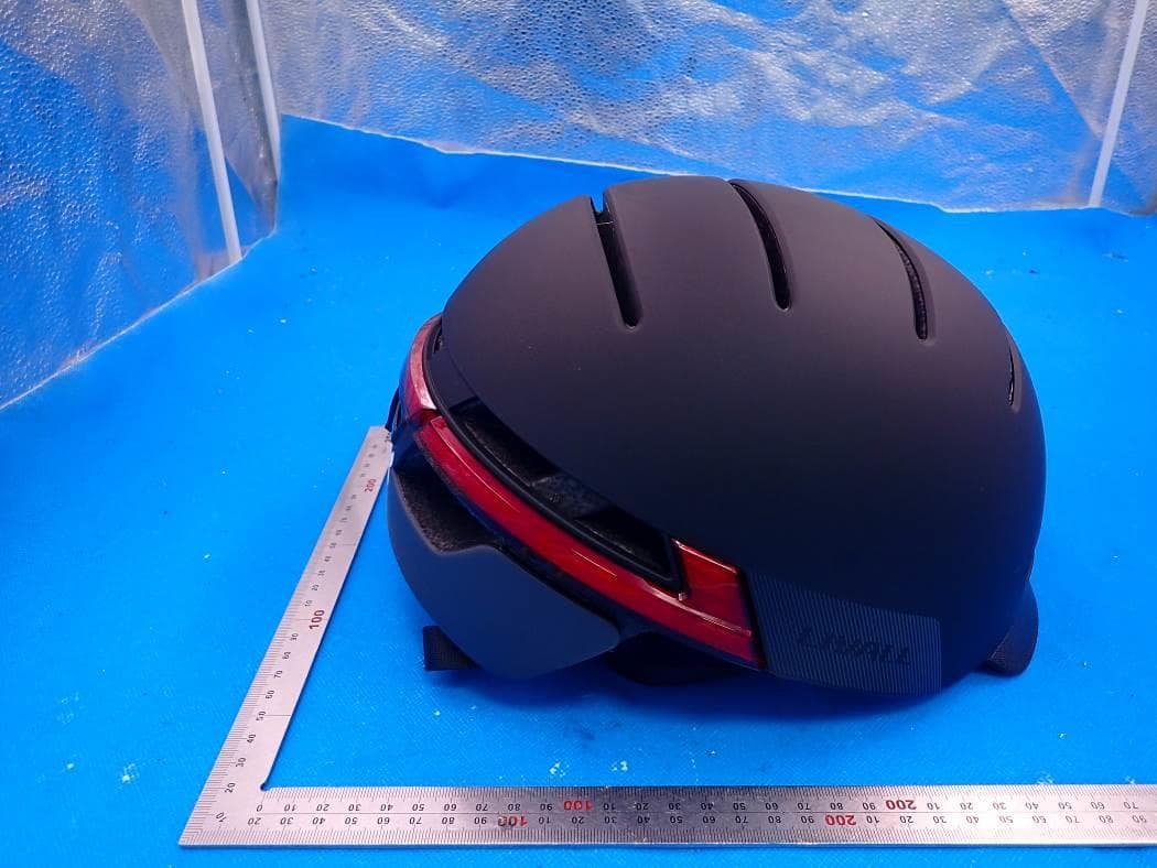
2AEKFBH51XX
Jul 15, 2021Bling Helmet
Equipment Class
DSS - Part 15 Spread Spectrum Transmitter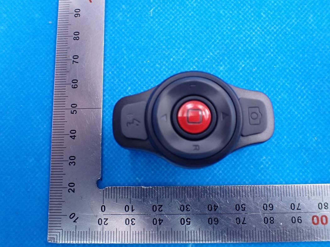
2AEKF-BR80
Jun 29, 2021Bling Remote Controller
Equipment Class
DTS - Digital Transmission System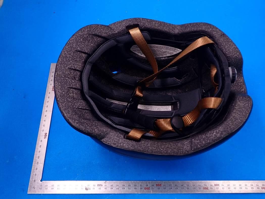
2AEKF-C20
May 20, 2021Smart Commuter Helmet C20
Equipment Class
DTS - Digital Transmission System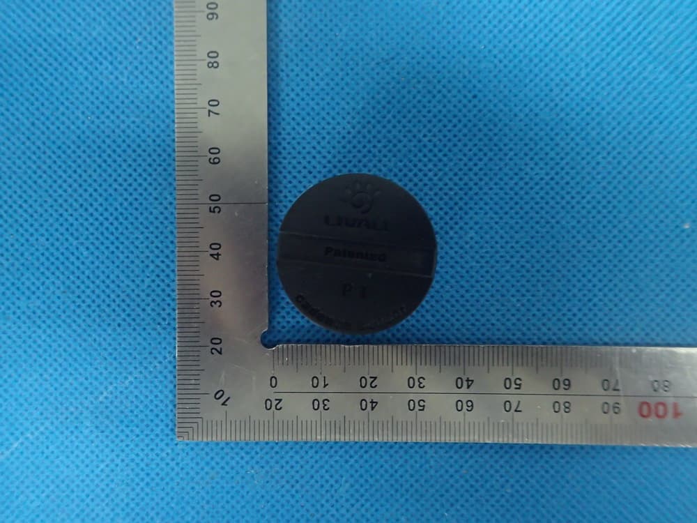
2AEKFP1
Nov 19, 2015Nano Cadence
Equipment Class
DXX - Part 15 Low Power Communication Device Transmitter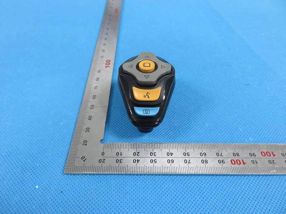
2AEKFBJ100
Nov 18, 2015Bling Jet
Equipment Class
DXX - Part 15 Low Power Communication Device Transmitter