2AEKFBH51XXBling Helmet
LIVALL Tech Co., Ltd.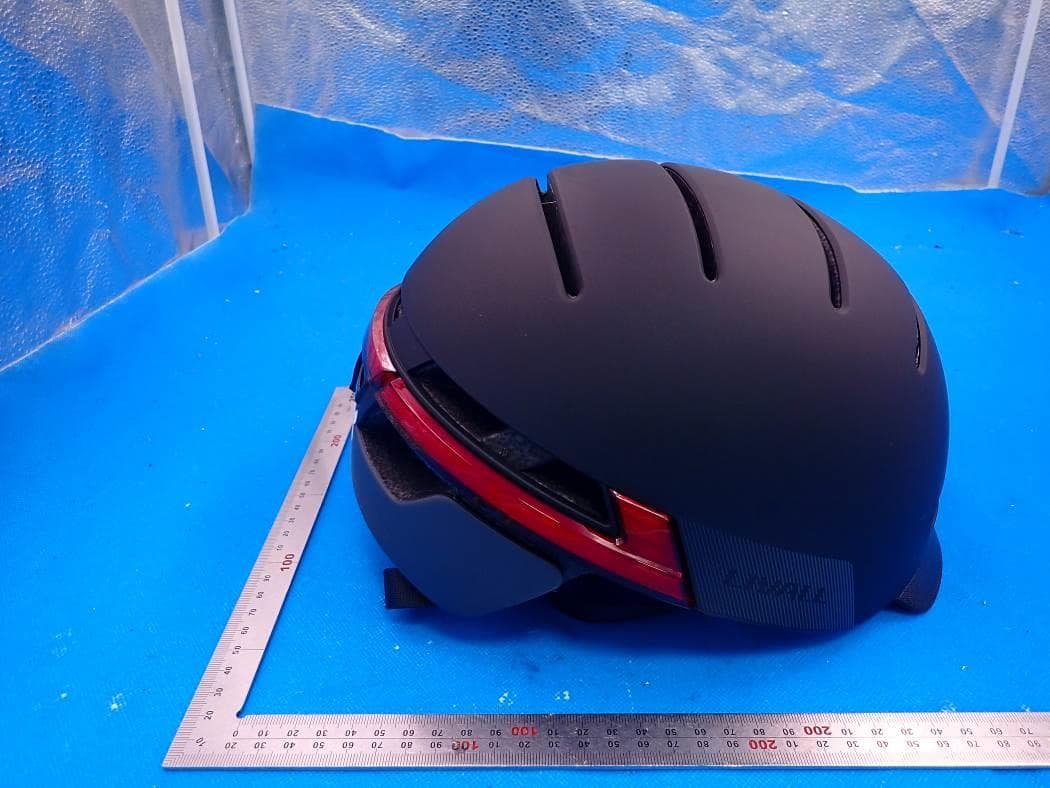
Click to zoom
Application Details
- Equipment Class
- DSS - Part 15 Spread Spectrum Transmitter
- Date of Grant
- Jul 15, 2021
- Application Purpose
- Original Equipment
- Date of Application
- Jul 15, 2021
- Equipment Note
- Bling Helmet
- Frequency Range
- 2402.00000000 - 2480.00000000
- Company
- LIVALL Tech Co., Ltd.
- Country
- China
Documents & Files
Document Text
Text extracted from the exhibit documents filed with the FCC. Open a document above to read the original.
Users Manual
www.livall.com Important Information and Warranty Card -1- I. Introduction and Declaration Before using a LIVALL helmet, please read all operating instructions and safety information in this Manual to ensure safe and proper use. LIVALL adheres to a strategy of sustainable development. This Manual (i.e., the Important Information and Warranty Card) will be updated from time to time, therefore, LIVALL reserves the right to make changes and improvements to any of the products described herein. The content of the Instructions shall be provided subject to the status of the products being manufactured. Unless otherwise specified in the applicable law, no explicit or tacit guarantee shall be made to the accuracy, reliability and content of this document. LIVALL reserves all rights. Without the prior written permission from LIVALL, it is prohibited to reproduce, deliver, distribute and store the contents of this document in any form. In case any problems are encountered while using this product, please contact our after-sales service for assistance. Product availability and related software and accessories may vary by region. For details, please consult our local distributors. The product may contain components and technical software that are controlled by export laws and regulations of China as well as other countries and regions. Any transfer in violation of the law is prohibited. LIVALL Important Information and Warranty Card Please read the Manual before using the product and keep it for future reference. -2- Please read the following simple guidelines. Failure to comply with these guidelines may be dangerous or break the law. 1. Keep the product out of reach of children and pets: Keep the product and all components out of reach of children and pets. Children and pets may swallow small parts, which may cause choking or other dangers. 2. Turn on only when safe: When use of electronic products is restricted or their use will cause interference or danger, please do not turn on the product. 3. Road safety: Please observe all related local traffic laws and regulations. Road safety should be considered a priority when using the product. 4. Interference: All wireless devices may be susceptible to interference, which could affect performance. 5. Turn off the helmet near medical equipment: Hospitals and healthcare facilities may use devices that are sensitive to wireless frequencies. Please follow all regulations. 6. Helmet should be switched off on aircraft: Please comply with all related restrictions as wireless devices may interfere with aircraft systems. 7. Helmet should be switched off in gas stations: Please do not use this product in gas stations or in areas near fuels, chemicals, etc. 8. Helmet should be switched off in areas near where blasting is being carried out: II.Safety Precautions -3- 1. Do not dispose of used batteries in general waste. For areas where there are regulations on recycling and disposal of used batteries, please comply with the related local regulations and help protect the environment. 2. Do not short circuit the batteries. When a metallic object (such as keys, jewelry, wires, coins or other conductive materials) inadvertently connects the positive and negative terminals of the batteries, a short circuit will occur. A short circuit may damage the battery or the connector, and may result in property damage or personal injury. Please put charged batteries in an appropriate place, paying particular attention to those in your pocket, wallet or other place where there might be metal objects. 3. Do not throw batteries into a fire or place them in a high temperature environment so as to avoid battery leakage, overheating, explosion or fire. 4. Do not disassemble, solder or modify the batteries; do not put the battery in locations subject to strong mechanical impact or hit the battery with a hard object, which will cause battery leakage, overheating, explosion or fire. III.Safety Precautions for Battery Use Comply with all related regulations and do not use this product in areas where blasting is in progress. 9. Accessories and batteries: Use only our approved accessories and batteries as other accessories and batteries may damage the product and be dangerous. 10. Connecting to other devices: When connecting the product to other devices, read the instructions of the other device for detailed safety instructions. Do not connect incompatible products. -4- 5. It is strictly prohibited to disassemble, crush, heat or burn built-in batteries; sharp objects, screwdrivers, etc. are forbidden from piercing or prying open the batteries. These actions may cause the battery to ignite or burn. 6. If a battery's electrolyte gets into your eyes, there is a risk of blindness. If the electrolyte is accidentally splashed into your eyes, do not rub your eyes. Immediately flush thoroughly with clean water and contact a hospital for treatment; in case a weak battery's electrolyte comes into contact with skin or clothes, wash immediately with soap and clean water, and consult a doctor immediately if necessary. 7. Do not use the battery for other purposes. Never use a damaged charger or battery. In case of overheating, discoloration, deformation, bulging, leakage and other anomalies that occur when batteries are in use, being charged or in storage, please stop using and replace so as to avoid safety issues. 8. Batteries are not waterproof. Do not use or charge a battery in the kitchen, bathroom or other hot and humid location. 9. When a battery is being charged, its temperature will rise. Please do not put the battery and combustibles (e.g.: bedding, clothing, books, etc.) together in case of fire. IV.Warning and Important Tips (For Helmets) 1. This helmet is designed especially for use with bicycles. Do not use it with motorcycles, motor- mounted bicycles or other sports equipment or during other sporting activities. 2. No safety helmet can completely avoid all unforseen impacts. Yet to achieve the …
Text truncated - open the document above for the full version.
Cover Letter(s)
LIVALL Tech Co., Ltd. Agent Authorization Company: LIVALL Tech Co., Ltd. Address: Room 904, 9F, R&D Building, Tsinghua Hi-Tech Park, Nanshan District, Shenzhen, China Product Name: Bling Helmet Model Number(s): BH51M Neo, BH51T Neo, BH51M, BH51T Product Description: Bling Helmet We authorize MiCOM Labs Inc., 575 Boulder Court, Pleasanton, California 94566, USA, to act on our behalf on all matters concerning the certification of above named equipment. We declare that MiCOM Labs Inc. is allowed to forward all information related to the approval and certification of equipment to the regulatory agencies as required and to discuss any issues concerning the approval application. Any and all acts carried out by MiCOM Labs on our behalf shall have the same effect as acts of our own. Signature: Date: 2021-07-12 Name: YongZheng Ye Company: LIVALL Tech Co., Ltd.
External Photos
External Photos ALL VIEW OF EUT EXTERNAL VIEW-1 OF EUT EXTERNAL VIEW-2 OF EUT EXTERNAL VIEW-3 OF EUT EXTERNAL VIEW-4 OF EUT EXTERNAL VIEW-5 OF EUT EXTERNAL VIEW-6 OF EUT EXTERNAL VIEW-7 OF EUT
ID Label/Location Info
FCC ID Label Location 3MM&15MM FCC ID: 2AEKFBH51XX
Internal Photos
Internal Photos OPEN VIEW OF EUT-1 VIEW OF BATTERY INTERNAL VIEW OF EUT-1 INTERNAL VIEW OF EUT-2 BLE Antenna BR/EDR Antenna INTERNAL VIEW OF EUT-3 INTERNAL VIEW OF EUT-4 INTERNAL VIEW OF EUT-5 INTERNAL VIEW OF EUT-6
RF Exposure Info
RF EXPOSURE EVALUATION 1. PRODUCT INFORMATION Product Description Bling Helmet Model Name BH51M Neo, BH51T Neo, BH51M, BH51T FCC ID 2AEKFBH51XX 2. EVALUATION METHOD According to 447498 D01 General RF Exposure Guidance v06 The 1-g and 10-g SAR test exclusion thresholds for 100 MHz to 6 GHz at test separation distances ≤ 50 mm are determined by: [(max. power of channel, including tune-up tolerance, mW)/(min. test separation distance, mm)] ·[√f(GHz)] ≤ 3.0 for 1-g SAR and ≤ 7.5 for 10-g extremity SAR. Where f(GHz) is the RF channel transmit frequency in GHz Power and distance are rounded to the nearest mW and mm before calculation 3. CALCULATION BT(BLE) P t =0.450dBm=1.11mW The value of the Maximum output power P t is referred to the test report of the CFR47 §15.247. The result for RF exposure evaluation SAR=(1.11mW /5mm) .[√2.402(GHz)]= 0.34<3.0 for 1-g SAR and ≤ 7.5 for 10-g extremity SAR. BT(BR&EDR) P t =7.418dBm=5.52mW The value of the Maximum output power P t is referred to the test report of the CFR47 §15.247. The result for RF exposure evaluation SAR=(5.52mW /5mm) .[√2.402(GHz)]= 1.71<3.0 for 1-g SAR and ≤ 7.5 for 10-g extremity SAR. Note: The BLE and BR&EDR can not transmit simultaneously. 4. CONCLUSION The SAR evaluation is not required.
Test Report
Page 1 of 78 FCC Test Report Report No.: AGC01993210403FE03 FCC ID : 2AEKFBH51XX APPLICATION PURPOSE : Original Equipment PRODUCT DESIGNATION : Bling Helmet BRAND NAME : LIVALL MODEL NAME : BH51M Neo, BH51T Neo, BH51M, BH51T APPLICANT : LIVALL Tech Co., Ltd. DATE OF ISSUE : Jun. 22, 2021 STANDARD(S) : FCC Part 15.247 REPORT VERSION : V1.0 Attestation of Global Compliance (Shenzhen) Co., Ltd Report No.: AGC01993210403FE03 Page 2 of 78 REPORT REVISE RECORD Report Version Revise Time Issued Date Valid Version Notes V1.0 / Jun. 22, 2021 Valid Initial Release Report No.: AGC01993210403FE03 Page 3 of 78 TABLE OF CONTENTS 1. VERIFICATION OF CONFORMITY .................................................................................................................. 5 2. GENERAL INFORMATION .............................................................................................................................. 6 2.1. PRODUCT DESCRIPTION ........................................................................................................................ 6 2.2. TABLE OF CARRIER FREQUENCYS ....................................................................................................... 6 2.3. RECEIVER INPUT BANDWIDTH .............................................................................................................. 7 2.4. EXAMPLE OF A HOPPING SEQUENCY IN DATA MODE ......................................................................... 7 2.5. EQUALLY AVERAGE USE OF FREQUENCIES AND BEHAVIOUR ......................................................... 7 2.6. RELATED SUBMITTAL(S) / GRANT (S) .................................................................................................... 8 2.7. TEST METHODOLOGY ............................................................................................................................. 8 2.8. SPECIAL ACCESSORIES ......................................................................................................................... 8 2.9. EQUIPMENT MODIFICATIONS ................................................................................................................. 8 2.10. ANTENNA REQUIREMENT..................................................................................................................... 8 3. MEASUREMENT UNCERTAINTY ................................................................................................................... 9 4. DESCRIPTION OF TEST MODES ................................................................................................................. 10 5. SYSTEM TEST CONFIGURATION ................................................................................................................ 11 5.1. CONFIGURATION OF EUT SYSTEM ...................................................................................................... 11 5.2. EQUIPMENT USED IN TESTED SYSTEM .............................................................................................. 11 5.3. SUMMARY OF TEST RESULTS .............................................................................................................. 11 6. TEST FACILITY .............................................................................................................................................. 12 7. PEAK OUTPUT POWER ................................................................................................................................ 13 7.1. MEASUREMENT PROCEDURE ............................................................................................................. 13 7.2. TEST SET-UP (BLOCK DIAGRAM OF CONFIGURATION) .................................................................... 13 7.3. LIMITS AND MEASUREMENT RESULT .................................................................................................. 14 8. 20DB BANDWIDTH ........................................................................................................................................ 19 8.1. MEASUREMENT PROCEDURE ............................................................................................................. 19 8.2. TEST SET-UP (BLOCK DIAGRAM OF CONFIGURATION) .................................................................... 19 8.3. LIMITS AND MEASUREMENT RESULTS ............................................................................................... 20 9. CONDUCTED SPURIOUS EMISSION........................................................................................................... 25 9.1. MEASUREMENT PROCEDURE ............................................................................................................. 25 Report No.: AGC01993210403FE03 Page 4 of 78 9.2. TEST SET-UP (BLOCK DIAGRAM OF CONFIGURATION) .................................................................... 25 9.3. MEASUREMENT EQUIPMENT USED .................................................................................................... 25 9.4. LIMITS AND MEASUREMENT RESULT .................................................................................................. 25 10. RADIATED EMISSION ................................................................................................................................. 46 10.1. MEASUREMENT PROCEDURE ........................................................................................................... 46 10.2. TEST SETUP ......................................................................................................................................... 48 10.3. LIMITS AND MEASUREMENT RESULT ............................................................................................... 49 10.4. TEST RESULT........................................................................................................................................ 49 11. NUMBER OF HOPPING FREQUENCY .............................................................…
Text truncated - open the document above for the full version.
Test Report
Report No.: AGC01993210403FE03 Page 55 of 78 Test result for band edge emission at restricted bands EUT Bling Helmet Model Name BH51M Neo Temperature 25°C Relative Humidity 55.4% Pressure 960hPa Test Voltage Normal Voltage Test Mode Mode 1 Antenna Horizontal Test Graph for Peak Measurement Test Graph for Average Measurement RESULT: PASS Report No.: AGC01993210403FE03 Page 56 of 78 EUT Bling Helmet Model Name BH51M Neo Temperature 25°C Relative Humidity 55.4% Pressure 960hPa Test Voltage Normal Voltage Test Mode Mode 1 Antenna Vertical Test Graph for Peak Measurement Test Graph for Average Measurement RESULT: PASS Report No.: AGC01993210403FE03 Page 57 of 78 EUT Bling Helmet Model Name BH51M Neo Temperature 25°C Relative Humidity 55.4% Pressure 960hPa Test Voltage Normal Voltage Test Mode Mode 3 Antenna Horizontal Test Graph for Peak Measurement Test Graph for Average Measurement RESULT: PASS Report No.: AGC01993210403FE03 Page 58 of 78 EUT Bling Helmet Model Name BH51M Neo Temperature 25°C Relative Humidity 55.4% Pressure 960hPa Test Voltage Normal Voltage Test Mode Mode 3 Antenna Vertical Test Graph for Peak Measurement Test Graph for Average Measurement RESULT: PASS Note: The factor had been edited in the “Input Correction” of the Spectrum Analyzer. The GFSK modulation is the worst case and recorded in the report. Report No.: AGC01993210403FE03 Page 59 of 78 11. NUMBER OF HOPPING FREQUENCY 11.1. MEASUREMENT PROCEDURE The EUT shall have its hopping function enabled. Use the following spectrum analyzer settings: 1. Span: The frequency band of operation. Depending on the number of channels the device supports, it may be necessary to divide the frequency range of operation across multiple spans, to allow the individual channels to be clearly seen. 2. RBW: To identify clearly the individual channels, set the RBW to less than 30% of the channel spacing or the 20 dB bandwidth, whichever is smaller. 3. VBW ≥ RBW. Sweep: Auto. Detector function: Peak. Trace: Max hold. 4. Allow the trace to stabilize. 11.2. TEST SETUP (BLOCK DIAGRAM OF CONFIGURATION) Same as described in section 8.2 11.3. MEASUREMENT EQUIPMENT USED The same as described in section 6 11.4. LIMITS AND MEASUREMENT RESULT Test Data of Number of Hopping Frequency Test Mode Number of Hopping Frequency Limits Pass or Fail GFSK Hopping 79 >=15 Pass Test Graphs of Number of Hopping Frequency Test_Graph_BR_HOP_ANT1_NA_1Mbps_Number of Hopping Note: The GFSK modulation is the worst case and recorded in the report. Report No.: AGC01993210403FE03 Page 60 of 78 12. TIME OF OCCUPANCY (DWELL TIME) 12.1. MEASUREMENT PROCEDURE The EUT shall have its hopping function enabled. Use the following spectrum analyzer settings: 1. Span: Zero span, centered on a hopping channel. 2. RBW shall be≤channel spacing and where possible RBW should be set >> 1 / T, where T is the expected dwell time per channel. 3. Sweep: As necessary to capture the entire dwell time per hopping channel; where possible use a video trigger and trigger delay so that the transmitted signal starts a little to the right of the start of the plot. The trigger level might need slight adjustment to prevent triggering when the system hops on an adjacent channel; a second plot might be needed with a longer sweep time to show two successive hops on a channel. 4. Detector function: Peak. Trace: Max hold. 5. Use the marker-delta function to determine the transmit time per hop. 6. Repeat the measurement using a longer sweep time to determine the number of hops over the period specified in the requirements. The sweep time shall be equal to, or less than, the period specified in the requirements. Determine the number of hops over the sweep time and calculate the total number of hops in the period specified in the requirements, using the following equation: (Number of hops in the period specified in the requirements) = (number of hops on spectrum analyzer) × (period specified in the requirements / analyzer sweep time) 7. The average time of occupancy is calculated from the transmit time per hop multiplied by the number of hops in the period specified in the requirements. 12.2. TEST SETUP (BLOCK DIAGRAM OF CONFIGURATION) Same as described in section 8.2 12.3. MEASUREMENT EQUIPMENT USED The same as described in section 6 12.4. LIMITS AND MEASUREMENT RESULT Test Data of Dwell Time Channel Time of Pulse for DH5 (ms) Number of hops in the period specified in the requirements Sweep Time (ms) Limit (ms) Pass or Fail 2402 2.878 27.0*4 310.824 400 Pass 2441 2.878 26.0*4 299.312 400 Pass 2480 2.878 27.0*4 310.824 400 Pass Note: The GFSK modulation is the worst case and recorded in the report. Report No.: AGC01993210403FE03 Page 61 of 78 Test Graphs of Dwell Time Test_Graph_BR_HOP_ANT1_NA_1Mbps_2402_Number of Burst Test_Graph_BR_HOP_ANT1_NA_1Mbps_2402_Time per Burst Report No.: AGC01993210403FE03 Page 62 of 78 Test_Graph_BR_HOP_ANT1_NA_1Mbps_2441_Number of Burst Test_Graph_BR_HOP_ANT1_NA_1Mbps_2441_Time per Burst Report No.: AGC01993210403FE03 Page 63 of 78 Test_Graph_BR_HOP_ANT1_NA_1Mbps_2480_Number of Burst Test_Graph_BR_HOP_ANT1_NA_1Mbps_2480_Time per Burst Report No.: AGC01993210403FE03 Page 64 of 78 13. FREQUENCY SEPARATION 13.1. MEASUREMENT PROCEDURE The EUT shall have its hopping function enabled. Use the following spectrum analyzer settings: 1. Span: Wide enough to capture the peaks of two adjacent channels. 2. RBW: Start with the RBW set to approximately 30% of the channel spacing; adjust as necessary to best identify the center of each individual channel. 3. Video (or average) bandwidth (VBW) ≥ RBW. 4. Sweep: Auto. e) Detector function: Peak. f) Trace: Max hold. g) Allow the trace to stabilize. Use the marker-delta function to determine the separation between the peaks of the adjacent channels. 13.2. TEST SETUP (BLOCK DIAGRAM OF CONFIGURATION) Same as described in section 6.2 13.3. MEASUREMENT EQUIPMENT USED The same as described in section 6.3 13.4. LIMITS AND MEASUREMENT RESULT Test Data of Frequen…
Text truncated - open the document above for the full version.
Test Setup Photos
Test Setup Photos RADIATED EMISSION TEST SETUP BELOW 1GHZ RADIATED EMISSION TEST SETUP ABOVE 1GHZ CONDUCTED EMISSION TEST SETUP CONDUCTED TEST SETUP
Contact Information
Applicant
YongZheng Ye
Technical Contact
Test Firm
Attestation of Global Compliance (Shenzhen) Co., LDoris Li
[email protected]+86-755-25234088
Technical Specifications
| # | Rule Parts | Frequency Range | Power Output |
|---|---|---|---|
| 1 | 15C | 2.40 GHz - 2.48 GHz | 5.50 mW |
Other Applications from LIVALL Tech Co., Ltd.

2AEKF-LTS21
Jun 07, 2022LTS21 Multifunction Sports Headphones
Equipment Class
DSS - Part 15 Spread Spectrum Transmitter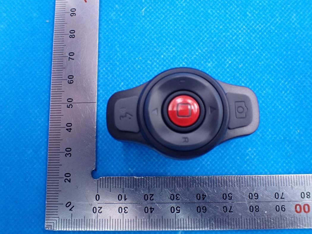
2AEKF-BR80
Jun 29, 2021Bling Remote Controller
Equipment Class
DTS - Digital Transmission System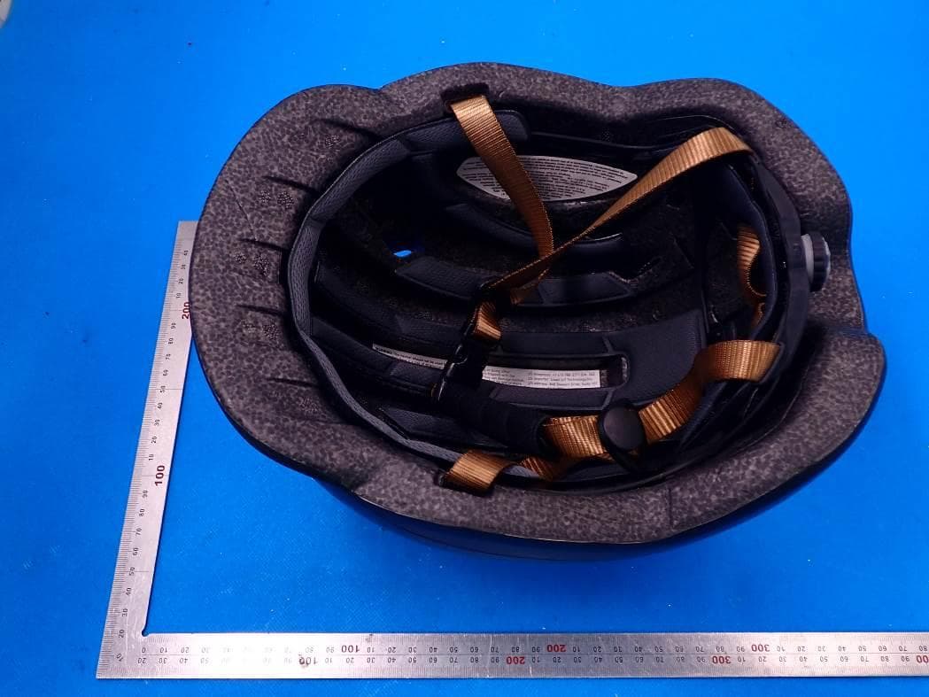
2AEKF-C20
May 20, 2021Smart Commuter Helmet C20
Equipment Class
DTS - Digital Transmission System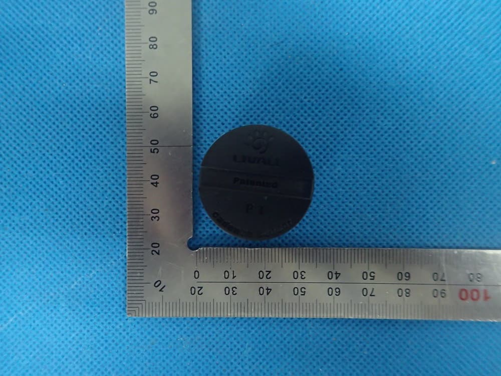
2AEKFP1
Nov 19, 2015Nano Cadence
Equipment Class
DXX - Part 15 Low Power Communication Device Transmitter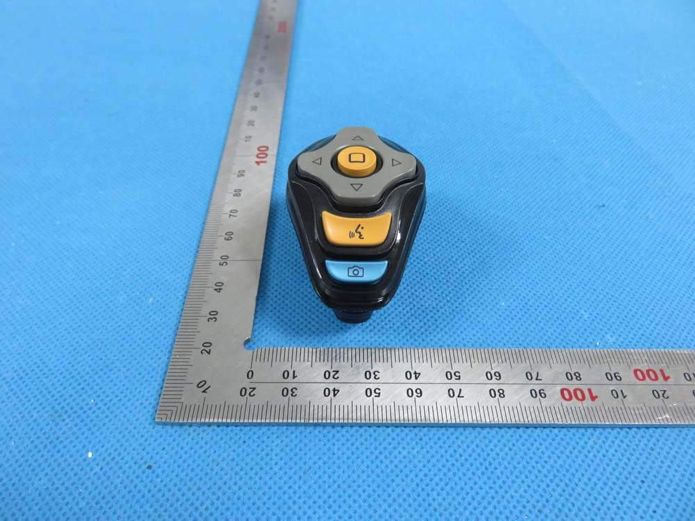
2AEKFBJ100
Nov 18, 2015Bling Jet
Equipment Class
DXX - Part 15 Low Power Communication Device Transmitter