2AEOCUT569Mobile 4W AM/FM/12W AM SSB CBRS Transceiver
President Electronics USA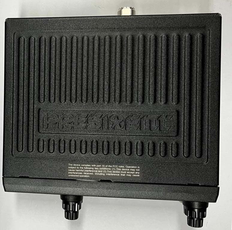
Click to zoom
Application Details
- Equipment Class
- CXX - Communications Rcvr for use w/ licensed Tx and CBs
- Date of Grant
- Jan 12, 2023
- Application Purpose
- Original Equipment
- Date of Application
- Jan 12, 2023
- Equipment Note
- Mobile 4W AM/FM/12W AM SSB CBRS Transceiver
- Frequency Range
- 162.40000000 - 162.55000000
- Company
- President Electronics USA
- Country
- United States
Documents & Files
Document Text
Text extracted from the exhibit documents filed with the FCC. Open a document above to read the original.
Users Manual
Owner’s manual / Manual del usuario Manuel d’utilisation / Manual do usuário 12/24 V Votre PRESIDENT MC KINLEY II FCC en un coup d’œilUma olhada no seu PRESIDENT MC KINLEY II FCC Un vistazo a vuestro PRESIDENT MC KINLEY II FCC Your PRESIDENT MC KINLEY II FCC at a glance 3 SUMÁRIO INSTALAÇÃO 54 UTILIZAÇÃO 56 FUNÇÕES COM A ALAVANCA PTT 61 MENUS 61 CARACTERÍSTICAS TÉCNICAS 65 GUIA DE PROBLEMAS 65 COMO TRANSMITIR OU RECEBER UMA MENSAGEM 66 GLOSSÁRIO 66 CONDIÇÕES GERAIS DE GARANTIA 69 T ABELAS DE FREQUÊNCIAS 70 SUMMAR Y INSTALLATION 5 HOW TO USE YOUR CB 7 FUNCTIONS WITH THE PTT SWITCH 11 MENU 12 TECHNICAL CHARACTERISTICS 15 TROUBLE SHOOTING 16 HOW TO TRANSMIT OR RECEIVE A MESSAGE 16 GLOSSAR Y 17 GENERAL WARRANTY CONDITIONS 19 FREQUENCY T ABLES 70 English SOMMAIRE INSTALLATION 37 UTILISATION 39 FONCTIONS AVEC LA PÉDALE D’ÉMISSION PTT 44 MENUS 44 CARACTÉRISTIQUES TECHNIQUES 48 GUIDE DE DÉP ANNAGE 49 COMMENT ÉMETTRE OU RECEVOIR UN MESSAGE 49 GLOSSAIRE 49 CONDITIONS GÉNÉRALE DE GARANTIE 52 T ABLEAUX DES FRÉQUENCES 70 Français Português SUMARIO INSTALACIÓN 21 UTILIZACIÓN 23 FUNCIONES CON LA PALANCA DE EMISIÓN PTT 28 MENÚS 28 CARACTERÍSTICAS TÉCNICAS 32 GUÍA DE PROBLEMAS 32 COMO EMITIR O RECIBIR UN MENSAJE 33 LÉXICO 33 GARANTÍA 35 TABLAS DE FRECUENCIAS 70 Español 4 WARNING ! • Very high output power. High temperature, install the transceiver in a very well ventilated place. • Before using, be careful never to transmit without first having connected the antenna (connection “B” situated on the back panel of the equipment) or without having set the SWR (Standing Wave Ratio)! Failure to do so may result in destruction of the power amplifier, which is not covered by the warranty. The warranty of this transceiver is valid only in the country of purchase. English WARNING: This product can expose you to chemicals including Lead, which is known to the State of California to cause cancer and birth defects or other repro- ductive harm. For more information go to www.P65Warnings.ca.gov. AVERTISSEMENT : Ce produit peut vous exposer à des agents chimiques, y compris le plomb, identifiés par l’État de Californie comme pouvant causer le cancer et des malformations congénitales ou autres effets nocifs sur la reproduction. Pour de plus amples informations, prière de consulter le site www.P65Warnings.ca.gov. 5 English Welcome to the world of the new generation of CB radios. The new PRESIDENT range gives you access to top performance CB equip- ment. With the use of up-to-date technology, which guarantees unprecedented quality, your PRESIDENT MC KINLEY II FCC is a new step in personal communication and is the surest choice for the most demanding of professional CB radio users. To ensure that you make the most of all its capacities, we advise you to read carefully this manual before installing and using your PRESIDENT MC KINLEY II FCC. A) INSTALLATION 1) WHERE AND HOW TO MOUNT YOUR MOBILE CB RADIO a) You should choose the most appropriate setting from a simple and practical point of view. b) Y our CB radio should not interfere with the driver or the passengers. c) Remember to provide for the passing and protection of different wires (e.g. power, antenna, accessory cabling) so that they do not interfere in any way with the driving of the vehicle. d) T o install your equipment, use the cradle (1) and the self-tapping screws (2) provided (drilling diameter 3.2 mm). Take care not to damage the vehicle’s electrical system while drilling the dash board. e) Do not forget to insert the rubber joints (3) between the CB and its support as these have a shock-absorbing effect which permits gentle orientation and tightening of the set. f) Choose where to place the microphone support and remember that the microphone cord must stretch to the driver without in- terfering with the controls of the vehicle. - N.B. : As the transceiver has a frontal microphone socket, it can be set into the dash board. In this case, you will need to add an external loud speaker to improve the sound quality of commu- nications (connector EXT.SP. situated on the back panel: C). Ask your dealer for advice on mounting your CB radio. 2) ANTENNA INSTALLATION a) Choosing your antenna - For CB radios, the longer the antenna, the better its r esults. Your dealer will be able to help you with your choice of antenna. b) Mobile antenna - Must be fixed to the vehicle where there is a maximum of metallic surface (ground plane), away from windscreen mountings. - If you already have a radio-telephone antenna installed, the CB antenna should be higher than this. MOUNTING DIAGRAM 6 - There are two types of antenna: pre-regulated which should be used on a good ground plane (e.g. car roof or lid of the boot), and adjustable which offer a much larger range and can be used on a smaller ground plane (see the § ADJUSTMENT OF SWR on page 6). - For an antenna which must be fixed by drilling, you will need a good contact between the antenna and the ground plane. To obtain this, you should lightly scratch the surface where the screw and tightening star are to be placed. - Be car eful not to pinch or flatten the coaxial cable (as this runs the risk of break down and/or short-circuiting). - Connect the antenna (B). a) Check that the battery is of 12 or 24 volts. b) Locate the positive and negative terminals of the battery (+ is red and - is black). Should it be necessary to lengthen the power cable, you should use the same or a superior type of cable. c) It is necessary to connect your CB to a permanent (+) and (-). We advise you to connect the power cable directly to the battery (as the connection of the CB cable to the wiring of the car-radio or other parts of the electrical circuit may, in some cases, increase the likelihood of interference). d) Connect the red wire (+) to the positive terminal of the battery and the black (-) wire to the negative termi- nal of the battery. e) Connect the power cable to your CB radio. W ARNING: Never re- place the original fuse with a fuse of a diff…
Text truncated - open the document above for the full version.
Cover Letter(s)
2AEOCUT569
Cover Letter(s)
© Celltech Labs Inc – 2022 ______________________________________________________________________________________ 21-364 Lougheed Road, Kelowna, British Columbia, Canada V1X 7R8 Tel: 1-250-765-7650 Fax: 1-250-765-7645 Date: 23 December 2022 To: Federal Communications Commission Authorization and Evaluation Division 7435 Oakland Mills Rd. Columbia, MD 21046 RE: New Certification Request, FCC ID: 2AEOCUT569 Dear FCC Representative This is a new certification request of FCC ID: 2AEOCUT569, Model: MC KINLEY II FCC. The MC KINLEY II FCC is a Mobile 4W, AM / FM / 12W AM SSB CBRS transceiver. The MC KINLEY II FCC is capable of transmitting Double-SideBand AM at 4W, Single-SideBand Suppressed Carrier AM at 12W PEP on both the lower and upper side bands and FM at 4W. In accordance with FCC 47 CFR Part 2, Subpart J, this Equipment is subject to certification to FCC 47 CFR Part 95, Subpart D. In addition, this Equipment receives weather channels in the 162.400 to 162.550MHz band. In accordance with FCC 47 CFR §15.101(a)(b), both the CBRS and weather receivers are subject to certification, Equipment Class CXX.. As per FCC 47 CFR §2.1091, an RF Exposure evaluation (MPE) is required for this Equipment. This Equipment is capable of Voice Activated Transmission (VOX), a 75% transmit duty factor applies. The results of the RF Exposure evaluation are based on the highest output power (12W) and appear in a separate report accompanied with this application. Should there be any questions or concerns please feel free to contact me. Thank you for your consideration. Sincerely, Art Voss, P.Eng.
External Photos
Applicant: President Electronics USA FCC ID: 2AEOCUT569 Test Report S/N: 45461787-R1.0 ISED ID 20240-UT569 ©2021 Celltech Labs Inc. This document is not to be reproduced in whole or in part without the expressed written permission of Celltech Labs Inc. Page 10 of 36 EXHIBIT 21 – PHOTOS – DUT EXTERNAL Figure E21.1 – External, General Applicant: President Electronics USA FCC ID: 2AEOCUT569 Test Report S/N: 45461787-R1.0 ISED ID 20240-UT569 ©2021 Celltech Labs Inc. This document is not to be reproduced in whole or in part without the expressed written permission of Celltech Labs Inc. Page 11 of 36 Figure E21.2 – External, Front Figure E21.3 – External, Back Applicant: President Electronics USA FCC ID: 2AEOCUT569 Test Report S/N: 45461787-R1.0 ISED ID 20240-UT569 ©2021 Celltech Labs Inc. This document is not to be reproduced in whole or in part without the expressed written permission of Celltech Labs Inc. Page 12 of 36 Figure E21.4 – External, Left Figure E21.5 – External, Right Applicant: President Electronics USA FCC ID: 2AEOCUT569 Test Report S/N: 45461787-R1.0 ISED ID 20240-UT569 ©2021 Celltech Labs Inc. This document is not to be reproduced in whole or in part without the expressed written permission of Celltech Labs Inc. Page 13 of 36 Figure E21.6 – External, Top Applicant: President Electronics USA FCC ID: 2AEOCUT569 Test Report S/N: 45461787-R1.0 ISED ID 20240-UT569 ©2021 Celltech Labs Inc. This document is not to be reproduced in whole or in part without the expressed written permission of Celltech Labs Inc. Page 14 of 36 Figure E21.7 – External, Bottom
ID Label/Location Info
Applicant: President Electronics USA FCC ID: 2AEOCUT569 Test Report S/N: 45461787-R1.0 ISED ID 20240-UT569 ©2021 Celltech Labs Inc. This document is not to be reproduced in whole or in part without the expressed written permission of Celltech Labs Inc. Page 8 of 36 EXHIBIT 14 – LABEL LOCATION Figure E14.1 – Label Location
ID Label/Location Info
Applicant: President Electronics USA FCC ID: 2AEOCUT569 Test Report S/N: 45461787-R1.0 ISED ID 20240-UT569 ©2021 Celltech Labs Inc. This document is not to be reproduced in whole or in part without the expressed written permission of Celltech Labs Inc. Page 7 of 36 EXHIBIT 13 – LABEL SAMPLE Figure E13.1 – Label Sample
Internal Photos
Applicant: President Electronics USA FCC ID: 2AEOCUT569 Test Report S/N: 45461787-R1.0 ISED ID 20240-UT569 ©2021 Celltech Labs Inc. This document is not to be reproduced in whole or in part without the expressed written permission of Celltech Labs Inc. Page 18 of 36 EXHIBIT 22 – PHOTOS – DUT INTERNAL Figure E22.1 – Internal, Top Removed Applicant: President Electronics USA FCC ID: 2AEOCUT569 Test Report S/N: 45461787-R1.0 ISED ID 20240-UT569 ©2021 Celltech Labs Inc. This document is not to be reproduced in whole or in part without the expressed written permission of Celltech Labs Inc. Page 19 of 36 Figure E22.2 – Internal, WX Applicant: President Electronics USA FCC ID: 2AEOCUT569 Test Report S/N: 45461787-R1.0 ISED ID 20240-UT569 ©2021 Celltech Labs Inc. This document is not to be reproduced in whole or in part without the expressed written permission of Celltech Labs Inc. Page 20 of 36 Figure E22.3 – Internal, Main PCB, Top Applicant: President Electronics USA FCC ID: 2AEOCUT569 Test Report S/N: 45461787-R1.0 ISED ID 20240-UT569 ©2021 Celltech Labs Inc. This document is not to be reproduced in whole or in part without the expressed written permission of Celltech Labs Inc. Page 21 of 36 Figure E22.4 – Internal, Main PCB, Bottom Applicant: President Electronics USA FCC ID: 2AEOCUT569 Test Report S/N: 45461787-R1.0 ISED ID 20240-UT569 ©2021 Celltech Labs Inc. This document is not to be reproduced in whole or in part without the expressed written permission of Celltech Labs Inc. Page 22 of 36 Figure E22.5 – Internal, Main PCB, WX Removed Applicant: President Electronics USA FCC ID: 2AEOCUT569 Test Report S/N: 45461787-R1.0 ISED ID 20240-UT569 ©2021 Celltech Labs Inc. This document is not to be reproduced in whole or in part without the expressed written permission of Celltech Labs Inc. Page 23 of 36 Figure E22.6 – Internal, Main PCB, Front Assembly Applicant: President Electronics USA FCC ID: 2AEOCUT569 Test Report S/N: 45461787-R1.0 ISED ID 20240-UT569 ©2021 Celltech Labs Inc. This document is not to be reproduced in whole or in part without the expressed written permission of Celltech Labs Inc. Page 24 of 36 Figure E22.7 – Internal, Main PCB, Front Assembly Component
Test Report
President Electronics USA Test Report Serial Number: Test Report Date: EMC Test Report - New Filing 45461788 R1.0 Project Number: 10 January 2023 © 2022 Celltech Labs Inc, This report shall not be reproduced in any form without the expressed written consent of Celltech Labs Inc. Information Technology Equipment (Including Digital Apparatus) FCC 47 CFR Part 15 Subpart B Unitentional Radiator (CXX) FCC Registration: CA3874 Ben Hewson, President Celltech Labs Inc. IC Registration 3874A 21-364 Lougheed Rd. Kelowna, BC, V1X 7R8 Canada Test Lab Certificate: 2470.01 — Limits and Methods of Measurement In Accordance With: 1606 Approved By: FCC ID:IC Registration Number Applicant: RSS-GEN, ICES-003 1007 Collier Center Way Naples, FL, 34110 USA Product Model Number / HVINProduct Name / PMN MC KINLEY II FCCMC KINLEY II FCC 2AEOCUT56920240-UT569 Table of Contents 1.0 REVISION HISTORY ........................................................................................................................................................ 3 2.0 CLIENT AND DUT INFORMATION .................................................................................................................................. 4 3.0 SCOPE .............................................................................................................................................................................. 5 4.0 TEST RESULT SUMMARY .............................................................................................................................................. 6 5.0 NORMATIVE REFERENCES ........................................................................................................................................... 7 6.0 FACILITIES AND ACCREDITATIONS ............................................................................................................................. 8 7.0 RADIATED RX EMISSIONS ............................................................................................................................................. 9 APPENDIX A – TEST SETUP DRAWINGS AND EQUIPMENT .......................................................................................... 15 APPENDIX B – EQUIPMENT LIST AND CALIBRATION ..................................................................................................... 17 APPENDIX C – MEASUREMENT INSTRUMENT UNCERTAINTY ..................................................................................... 18 END OF REPORT ................................................................................................................................................................. 18 Table of Figures Figure A.1 – Test Setup Radiated Emissions Measurements Below 30MHz ....................................................................... 15 Figure A.2 – Test Setup Radiated Emissions Measurements 30-1000MHz ........................................................................ 16 Figure A.3 – Test Setup Radiated Emissions Measurements 30-1000MHz ........................................................................ 16 Table of Plots Plot 7.1 – Radiated Rx Emissions OATS, 9kHz - 30MHz, Front .......................................................................................... 10 Plot 7.2 – Radiated Rx Emissions OATS, 9kHz - 30MHz, Side ............................................................................................ 11 Plot 7.3– Radiated Spurious Emissions OATS, 30 - 1000MHz, Horizontal .......................................................................... 12 Plot 7.4– Radiated Spurious Emissions OATS, 30 - 1000MHz, Vertical .............................................................................. 13 Table of Tables Table 7.1 – Summary of Radiated Rx Emissions ................................................................................................................. 14 Table A.1 – Setup - Radiated Emissions Equipment ............................................................................................................ 15 1.0 REVISION HISTORY ReportRevised RevisionSection 1.0All Revision History Samples Tested By: Report Prepared By: Art Voss, P.Eng. Art Voss, P.Eng. Report Reviewed By: Date(s) of Evaluation: 2 -3 November 2022 Initial ReleaseArt Voss10 January 2023 Art Voss Description of Revision Revised By Revision Date 2.0 CLIENT AND DUT INFORMATION Applicant Name (FCC) 2AEOCUT569 20240-UT569 Device Type: Device Model(s) / HVIN: Device Marketing Name / PMN: Firmware Version ID Number / FVIN: Host Marketing Name / HMN: Test Sample Serial No.: Equipment Class (FCC): Transmit Frequency Range: Test Channels: Antenna Make and Model: Antenna Type and Gain: Modulation: Mode: Weather Receiver (WX): DUT Power Source: DUT Dimensions [WxLxH] Deviation(s) from standard/procedure: Modification of DUT: Applicant Address (FCC) None None AM / FM / AM Upper-SideBand / AM Lower-SideBand Simplex 12 - 24VDC 172mm x 148mm x 52mm 0dBi (Typical), 3dBi (Max) Licensed Non-Broadcast Station Transmitter (TNB) AM Double-SideBand, FM: 8kHz FCC ID: IC ID: n/a 162.4 - 162.55MHz AM Single-SideBand: 12W (40.8dBm) AM Single-SideBand: 4kHz Mobile 4W AM / FM / 12W AM SSB CBRS Transceiver Manuf. Max. Rated Output Power: Manuf. Max. Rated BW: #2 MC KINLEY II FCC - - Client Information 26.965MHz - 27.405MHz 40 Channels AM Double-SideBand, FM: 4W (36dBm) President Electronics USA 1007 Collier Center Way Device Identifier(s): Naples, FL, 34110 DUT Information MC KINLEY II FCC USA 3.0 SCOPE Preface: President Electronics US A Application: RF Exposure: As per FCC 47 CFR §2.1091 and Canada Health Safety Code 6, an RF Exposure (MPE) evaluation is required for this Equipment and the results of the RF Exposure (MPE) evaluation appear in a separate report. Since this equipment is capable of multiple transmission modes, only the highest power mode is considered. This Certification Report was prepared on behalf of: ,(the ' Applicant''), in accordance with the ap…
Text truncated - open the document above for the full version.
Test Setup Photos
Applicant: President Electronics USA FCC ID: 2AEOCUT569 Test Report S/N: 45461787-R1.0 ISED ID 20240-UT569 ©2021 Celltech Labs Inc. This document is not to be reproduced in whole or in part without the expressed written permission of Celltech Labs Inc. Page 26 of 39 EXHIBIT 23 – PHOTOS – EMC AND SAR SETUP Figure E23.1 – Setup, Below 30MHz, without Accessories Applicant: President Electronics USA FCC ID: 2AEOCUT569 Test Report S/N: 45461787-R1.0 ISED ID 20240-UT569 ©2021 Celltech Labs Inc. This document is not to be reproduced in whole or in part without the expressed written permission of Celltech Labs Inc. Page 27 of 39 Figure E23.2 – Setup, Below 30MHz, with Accessories Applicant: President Electronics USA FCC ID: 2AEOCUT569 Test Report S/N: 45461787-R1.0 ISED ID 20240-UT569 ©2021 Celltech Labs Inc. This document is not to be reproduced in whole or in part without the expressed written permission of Celltech Labs Inc. Page 28 of 39 Figure E23.3 – Setup, Above 30MHz, without Accessories Applicant: President Electronics USA FCC ID: 2AEOCUT569 Test Report S/N: 45461787-R1.0 ISED ID 20240-UT569 ©2021 Celltech Labs Inc. This document is not to be reproduced in whole or in part without the expressed written permission of Celltech Labs Inc. Page 29 of 39 Figure E23.4 – Setup, Above 30MHz, with Accessories Applicant: President Electronics USA FCC ID: 2AEOCUT569 Test Report S/N: 45461787-R1.0 ISED ID 20240-UT569 ©2021 Celltech Labs Inc. This document is not to be reproduced in whole or in part without the expressed written permission of Celltech Labs Inc. Page 30 of 39 Figure E23.5 – Setup, DUT with Accessories Applicant: President Electronics USA FCC ID: 2AEOCUT569 Test Report S/N: 45461787-R1.0 ISED ID 20240-UT569 ©2021 Celltech Labs Inc. This document is not to be reproduced in whole or in part without the expressed written permission of Celltech Labs Inc. Page 31 of 39 Figure E23.6 – Setup, DUT with Accessories Applicant: President Electronics USA FCC ID: 2AEOCUT569 Test Report S/N: 45461787-R1.0 ISED ID 20240-UT569 ©2021 Celltech Labs Inc. This document is not to be reproduced in whole or in part without the expressed written permission of Celltech Labs Inc. Page 32 of 39 Figure E23.7 – Setup, Conducted and Modulation Response Applicant: President Electronics USA FCC ID: 2AEOCUT569 Test Report S/N: 45461787-R1.0 ISED ID 20240-UT569 ©2021 Celltech Labs Inc. This document is not to be reproduced in whole or in part without the expressed written permission of Celltech Labs Inc. Page 33 of 39 Figure E23.8 – Setup, Conducted and Modulation Response Applicant: President Electronics USA FCC ID: 2AEOCUT569 Test Report S/N: 45461787-R1.0 ISED ID 20240-UT569 ©2021 Celltech Labs Inc. This document is not to be reproduced in whole or in part without the expressed written permission of Celltech Labs Inc. Page 34 of 39 Figure E23.9 – Setup, Frequency Stability Applicant: President Electronics USA FCC ID: 2AEOCUT569 Test Report S/N: 45461787-R1.0 ISED ID 20240-UT569 ©2021 Celltech Labs Inc. This document is not to be reproduced in whole or in part without the expressed written permission of Celltech Labs Inc. Page 35 of 39 Figure E23.10 – Setup, Frequency Stability Applicant: President Electronics USA FCC ID: 2AEOCUT569 Test Report S/N: 45461787-R1.0 ISED ID 20240-UT569 ©2021 Celltech Labs Inc. This document is not to be reproduced in whole or in part without the expressed written permission of Celltech Labs Inc. Page 36 of 39 Figure E23.11 – Setup, RE Rx (DXX) Below 30MHz, with Accessories Applicant: President Electronics USA FCC ID: 2AEOCUT569 Test Report S/N: 45461787-R1.0 ISED ID 20240-UT569 ©2021 Celltech Labs Inc. This document is not to be reproduced in whole or in part without the expressed written permission of Celltech Labs Inc. Page 37 of 39 Figure E23.12 – Setup, RE Rx (DXX) Above 30MHz, with Accessories
Contact Information
Applicant
Kavi Sharma(General Manager)
Test Firm
CELLTECH LABS INC.Ben Hewson
Technical Specifications
| # | Rule Parts | Frequency Range | Power Output |
|---|---|---|---|
| 2 | 15B | 162.4 MHz - 162.55 MHz | - |
Other Applications from President Electronics USA
2AEOCPC214
Feb 20, 2024BT MIKE
Equipment Class
DTS - Digital Transmission System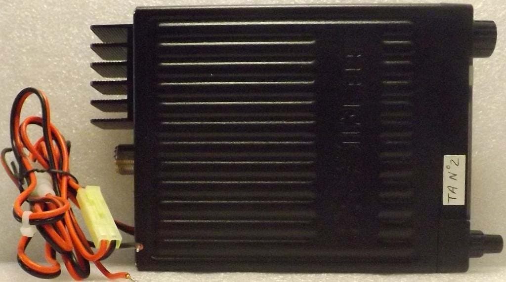
2AEOCPC212
Dec 18, 2022Mobile 4W AM/FM CBRS Transceiver
Equipment Class
TNB - Licensed Non-Broadcast Station Transmitter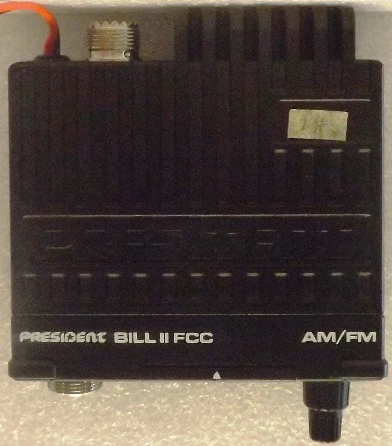
2AEOCPC210
Apr 13, 2022Mobile 4W AM/FM CBRS Transceiver
Equipment Class
CXX - Communications Rcvr for use w/ licensed Tx and CBs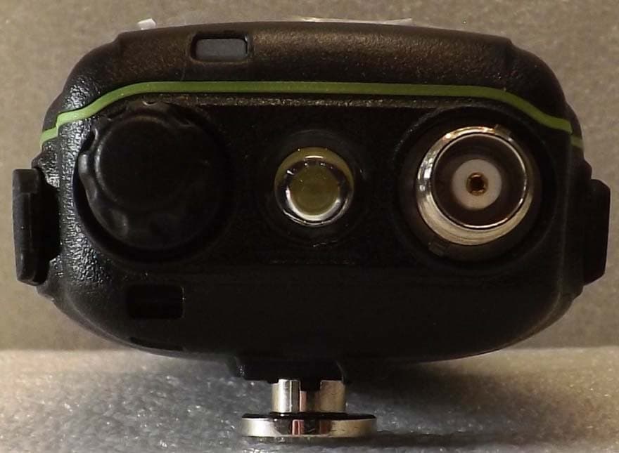
2AEOCPC207
Feb 04, 2021Portable Handheld 4W AM CBRS Transceiver
Equipment Class
TNB - Licensed Non-Broadcast Station Transmitter