2AEPIELEMENT5PLUSSMARTPHONE
COLOMBIANA DE COMERCIO S.A.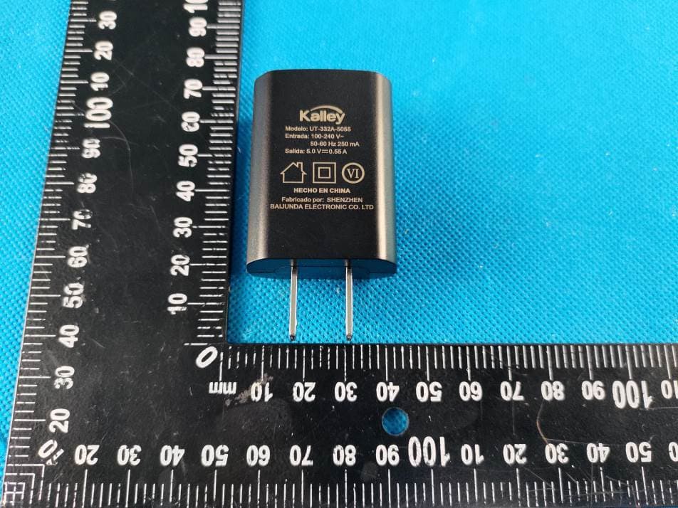
Click to zoom
Application Details
- Equipment Class
- DTS - Digital Transmission System
- Date of Grant
- Oct 20, 2022
- Application Purpose
- Original Equipment
- Date of Application
- Oct 20, 2022
- Equipment Note
- SMARTPHONE
- Frequency Range
- 2412.00000000 - 2462.00000000
- Company
- COLOMBIANA DE COMERCIO S.A.
- Country
- Colombia
Documents & Files
Document Text
Text extracted from the exhibit documents filed with the FCC. Open a document above to read the original.
Users Manual
1 Know your phone 2 Table of Contents Know your phone ...................... 错误!未定义书签。 1. SIM/SD Card Installatioan ........ 6 Install SIM card ....................................................... 6 Install T-flash card ................................................... 7 2. Menu functions ......................... 8 Contacts .................................................................. 8 Message ................................................................. 8 Phone ..................................................................... 8 Gmail ...................................................................... 8 Camera ................................................................... 8 Gallery .................................................................... 9 FM Radio ................................................................ 9 YT Music ................................................................. 9 Files ........................................................................ 9 Bluetooth ................................................................. 9 SIM Toolkit ............................................................ 10 Calendar ............................................................... 10 Clock ..................................................................... 10 Calculator .............................................................. 10 3. Accessories ............................ 11 4. FCC Regulations ..................... 12 5. SAR .......................................... 14 6. Technical Specifications ........ 15 3 Foreword Honorific mobile phones user, thank you for choosing our mobile phone! Our cellular phones is according with the communication industry standards of PRC, and also according with the standards of European, and are approved for GSM networks. Your phone may be used internationally with various networks depending on your roaming arrangements with your service provider. To use this phone you must subscribe to a GSM service from a provider. We have included many features in this device but their function depends on the features available with your subscribed wireless network. Please contact your service provider for more information. We strongly recommend you carefully read and understand this manual before using your phone in order to keep it under best conditions for your effective usage and utmost satisfaction. Safety Never attempt to disassemble your phone. You alone are responsible for how you use your phone and any consequences of its use. As a general rule, always switch off your phone wherever the use of a phone is prohibited. Use of your phone is subject to safety measures designed to protect users and their environment. Do not use your phone in damp areas (bathroom, swimming pool...). Protect it from liquids and other moisture. Do not expose your phone to extreme temperatures lower than - 10°C and higher than + 55°C. Please note that the ambient temperature range for normal charging of mobile phones is 0 °C ~ 45 °C. Do not charge at an ambient temperature below 0 ° C or above 45 ° C, as this will result in reduced battery performance and reduced life. Charging for too long at too high or too low ambient 4 temperatures can damage unfilled or swelled batteries, and there is a risk of battery explosion The physicochemical processes created by chargers impose temperature limits when charging the battery. Your phone automatically protects the batteries in extreme temperatures. Do not leave your phone within the reach of small children (certain removable parts may be accidentally ingested). Electrical safety Only use the chargers listed in the manufacturer’s catalogue. Using any other charger may be dangerous; it would also invalidate your warranty. Line voltage must be exactly the one indicated on the charger’s serial plate. Aircraft safety When traveling by plane, you will need to switch your phone off when so instructed by the cabin crew or the warning signs. Using a mobile phone may be dangerous to the operation of the aircraft and may disrupt the phone network. Its use is illegal and you could be prosecuted or banned from using cellular networks in the future if you do not abide by these regulations. Explosive materials Please comply with warning signs at petrol station when personnel asking you to switch your phone off. You will need to comply with radio equipment usage restrictions in places such as chemical plants, fuel depots and at any location where blasting operations are under way. Electronic equipment To avoid the risk of demagnetization, do not let electronic devices close to your phone for a long time. Electronic medical equipment Your phone is a radio transmitter which may interfere with electronic medical equipment or implants, such as hearing aids, pacemakers, insulin pumps, etc. It is recommended that a minimum separation of 5mm be maintained between the phone and an implant. Your doctor or the manufacturers of such equipment will be able to give you any advice you may need in 5 this area. Hospitals Always make sure that your phone is switched off in hospitals when so instructed by warning signs or by medical staff. Road safety Do not use your phone when driving. In order to give your full attention to driving, stop and park safely before making a call. You must comply with any current legislation. Distance of operation This phone model has been tested and meets radiofrequency exposure guidelines when used As follows: ·Against the ear: place or receive a phone call and hold the phone as you would a wire line telephone. ·Body worn: when transmitting, place the phone in a carry accessory that contains no metal and positions the phone a minimum of 5mm form your body. Use of other accessories may not ensure compliance with radiofrequency exposure guidelines. If you do not use a body worn accessory and are not holding the phone at the ear, position the phone a minimum of 5mm from your body, ·Data oper…
Text truncated - open the document above for the full version.
Attestation Statements
COLOMBIANA DE COMERCIO S.A. Date: 2022-10-19 Federal Communications Commission Authorization and Evaluation Division 7435 Oakland Mills Road Columbia, MD 21046 FCC ID: 2AEPIELEMENT5PLUS To Whom It May Concern: This letter is to statement that ELEMENT 5 PLUS / SMARTPHONE. has been tested according to FCC Part 15B by Waltek Testing Group Co., Ltd. (Test Report No.: WTD22D09182233E). And the SDOC file, meetting the requirements of the FCC regulations, would been provided when the device is sold by the responsible party in US. The service will not be sold until the SDOC is provided. If the sale does not have an SDOC, all responsibility is the responsibility of the applicant. Sincerely, Signature [Julian Orozco] [Manager] [COLOMBIANA DE COMERCIO S.A.]
Cover Letter(s)
COLOMBIANA DE COMERCIO S.A. Date: Oct. 19, 2022 Federal Communications Commission Authorization and Evaluation Division Confidentiality Request regarding application for certification of FCC ID: 2AEPIELEMENT5PLUS Pursuant to Sections 0.457 and 0.459 of the Commission’s Rules, we hereby request confidential treatment of information accompanying this application as outlined below: Exhibit Type File Name Schematics Block Diagram Operational Description Schematics.pdf Block Diagram.pdf Operational Description.pdf Part List PCB Layout Schematics Tune-up Procedure Part List.pdf PCB Layout Schematics.pdf Tune-up Procedure.pdf The above materials contain trade secrets and proprietary information not customarily released to the public. The public disclosure of these materials may be harmful to the applicant and provide unjustified benefits to its competitors. The applicant understands that pursuant to Section 0.457 of the Rules, disclosure of this application and all accompanying documentation will not be made before the date of the Grant for this application. Sincerely, COLOMBIANA DE COMERCIO S.A. Signature Julian Orozco / Manager Typed name and Title
Cover Letter(s)
COLOMBIANA DE COMERCIO S.A. Date: 10/19/2022 To: Federal Communications Commission 7435 Oakland Mills Road Columbia, MD To Whom It May Concern: We, COLOMBIANA DE COMERCIO S.A., state that our device, FCC ID: 2AEPIELEMENT5PLUS, has a battery, but the battery will not be placed in the battery compartment when deliver y, the label is v isible to the users as they purchase the products and install the battery. Sincerely, Signature [Julian Orozco (Name)] [Manager (Title)] [COLOMBIANA DE COMERCIO S.A. (Company name)]
Cover Letter(s)
COLOMBIANA DE COMERCIO S.A. FCC ID: 2AEPIELEMENT5PLUS POWER OF ATTORNEY Date: Oct. 19, 2022 Federal Communications Commission Authorization and Evaluation Division 7435 Oakland Mills Road Columbia, MD 21046 To Whom It May Concern: We, the undersigned, hereby authorize Waltek Testing Group Co., Ltd. (Philo Zhong) on our behalf, to apply to the Federal Communications Commission on our equipment. Any and all acts carried out by Waltek Testing Group Co., Ltd. (Philo Zhong) on our behalf shall have the same effect as acts of our own. This authorization expires on Oct. 18, 2023. This is to advise that we are in full compliance with the Anti-Drug Abuse Act. We, COLOMBIANA DE COMERCIO S.A. are not subject to a denial of federal benefits pursuant to Section 5301 of the Anti-Drug Act of 1988, 21 USC853a, and no party to the application is subject to a denial of federal benefits pursuant to that section. Sincerely, COLOMBIANA DE COMERCIO S.A. Signature Julian Orozco / Manager Typed name and Title
External Photos
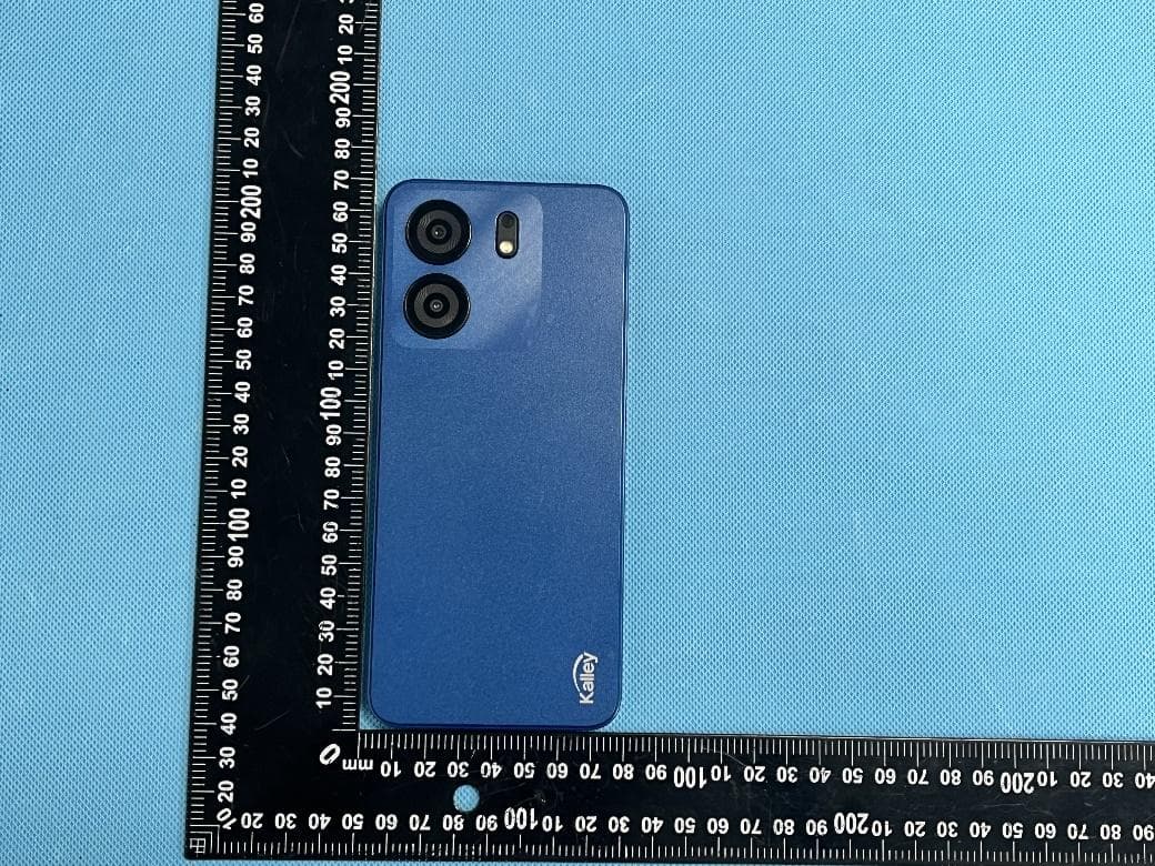
Appendix-ELEMENT 5 PLUS-Photos Page 4 of 16 EUT – External View Model ELEMENT 5 PLUS FCC ID: 2AEPIELEMENT5PLUS Appendix-ELEMENT 5 PLUS-Photos Page 5 of 16 Appendix-ELEMENT 5 PLUS-Photos Page 6 of 16 Appendix-ELEMENT 5 PLUS-Photos Page 7 of 16 Appendix-ELEMENT 5 PLUS-Photos Page 8 of 16 Appendix-ELEMENT 5 PLUS-Photos Page 9 of 16
ID Label/Location Info
ELEMENT 5 PLUS Label Sample and Location
Internal Photos
Appendix-ELEMENT 5 PLUS-Photos Page 10 of 16 EUT – Internal View Model ELEMENT 5 PLUS FCC ID: 2AEPIELEMENT5PLUS GSM/WCDMA/LTE ANT. BT/WIFI/BLE ANT. Appendix-ELEMENT 5 PLUS-Photos Page 11 of 16 Appendix-ELEMENT 5 PLUS-Photos Page 12 of 16 Appendix-ELEMENT 5 PLUS-Photos Page 13 of 16
Internal Photos
Appendix-ELEMENT 5 PLUS-Photos Page 14 of 16 Appendix-ELEMENT 5 PLUS-Photos Page 15 of 16 Appendix-ELEMENT 5 PLUS-Photos Page 16 of 16 =====End======
RF Exposure Info
Waltek Testing Group (Shenzhen) Co., Ltd. Http://www.waltek.com.cn Page 1 of 143 TEST REPORT Reference No. .................... : WTD22X09182242W001 FCC ID ................................ : 2AEPIELEMENT5PLUS Applicant ........................... : COLOMBIANA DE COMERCIO S.A. Address ............................. : Car. 43E No 8-71, Medellin, Colombia Manufacturer ..................... MOBIWIRE MOBILES (NINGBO) CO.,LTD Address ............................. Ningbo Fenghua No.999,Dacheng East Road,Fenghua,Zhejiang,China Product Name ................... : SMARTPHONE Model No.. .......................... : ELEMENT 5 PLUS Standards .......................... : FCC Part 2.1093 IEEE Std C95.1: 2019 IEEE Std C95.3: 2002 + Rev. 2008 IEEE 1528: 2013 Date of Receipt sample .... : 2022-05-16 Date of Test........................ : 2022-05-16 to 2022-06-22; 2022-09-07 to 2022-09-22 Date of Issue ..................... : 2022-09-22 Test Report Form No. ....... : WTX_IEEE_1528_2013W Test Result ......................... : Pass Remarks: The results shown in this test report refer only to the sample(s) tested, this test report cannot be reproduced, except in full, without prior written permission of the company. The report would be invalid without specific stamp of test institute and the signatures of approver. Prepared By: Waltek Testing Group (Shenzhen) Co., Ltd. Address: 1/F., Room 101, Building 1, Hongwei Industrial Park, Liuxian 2nd Road, Block 70 Bao'an District, Shenzhen, Guangdong, China Tel.: +86-755-33663308 Fax.: +86-755-33663309 Email: [email protected] Tested by: Approved by: Jack Sun Silin Chen Reference No.: WTD22X05095859W001 Page 2 of 143 Waltek Testing Group (Shenzhen) Co., Ltd. Http://www.waltek.com.cn TABLE OF CONTENTS 1. General Information ................................................................................................................................................... 4 1.1 Product Description for Equipment Under Test (EUT) ......................................................................................... 4 1.2 Test Standards .................................................................................................................................................... 7 1.3 Test Methodology ................................................................................................................................................ 7 1.4 Test Facility ......................................................................................................................................................... 7 2. Summary of Test Results .......................................................................................................................................... 8 3. Specific Absorption Rate (SAR) ................................................................................................................................ 9 3.1 Introduction .......................................................................................................................................................... 9 3.2 SAR Definition ..................................................................................................................................................... 9 4. SAR Measurement System ...................................................................................................................................... 10 4.1 The Measurement System ................................................................................................................................ 10 4.2 Probe ................................................................................................................................................................. 10 4.3 Probe Calibration Process ................................................................................................................................. 12 4.4 Phantom ............................................................................................................................................................ 13 4.5 Device Holder .................................................................................................................................................... 13 4.6 Test Equipment List ........................................................................................................................................... 14 5. Tissue Simulating Liquids ....................................................................................................................................... 15 5.1 Composition of Tissue Simulating Liquid ........................................................................................................... 15 5.2 Tissue Dielectric Parameters for Head and Body Phantoms ............................................................................. 16 5.3 Tissue Calibration Result ................................................................................................................................... 17 6. SAR Measurement Evaluation ................................................................................................................................ 18 6.1 Purpose of System Performance Check ............................................................................................................ 18 6.2 System Setup .................................................................................................................................................... 18 6.3 Validation Results .............................................................................................................................................. 19 7. EUT Testing Position ............................................................................................................................................... 21 7.1 Define Two Imaginary Lines on The Handset ........................................................................…
Text truncated - open the document above for the full version.
RF Exposure Info
Page: 1/10 Ref : ACR.197.12.21.BES.B Cancel and replace the report ACR.197.12.21.BES.A WALTEK TESTING GROUP (SHENZHEN) CO., LTD 1/F., ROOM 101, BUILDING 1, HONGWEI INDUSTRIAL PARK, LIUXIAN 2ND ROAD, BLOCK 70 BAO’AN DISTRICT, SHENZHEN, GUANGDONG , CHINA MVG COMOSAR DOSIMETRIC E-FIELD PROBE SERIAL NO.: SN 18/21 EPGO356 Calibrated at MVG Z.I. de la pointe du diable Technopôle Brest Iroise – 295 avenue Alexis de Rochon 29280 PLOUZANE - FRANCE Calibration date: 07/16/2021 Accreditations #2-6789 Scope available on www.cofrac.fr Summary: This document presents the method and results from an accredited COMOSAR E-Field Probe calibration performed at MVG, using the CALIPROBE test bench, for use with a MVG COMOSAR system only. The test results covered by accreditation are traceable to the International System of Units (SI). COMOSAR E-Field Probe Calibration Report COMOSAR E-FIELD PROBE CALIBRATION REPORT Ref: ACR.197.12.21.BES.B Page: 2/10 Template_ACR.DDD.N.YY.MVGB.ISSUE_COMOSAR Probe vI This document shall not be reproduced, except in full or in part, without the written approval of MVG. The information contained herein is to be used only for the purpose for which it is submitted and is not to be released in whole or part without written approval of MVG. Name Function Date Signature Prepared by : Jérôme Le Gall Measurement Responsible 7/16/2021 Checked by : Jérôme Luc Technical Manager 7/16/2021 Approved by : Yann Toutain Laboratory Director 8/23/2021 Customer Name Distribution : Waltek Testing Group (Shenzhen) Co., Ltd Issue Name Date Modifications A Jérôme Luc 7/16/2021 Initial release B Jérôme Luc 8/16/2021 Change customer name/address COMOSAR E-FIELD PROBE CALIBRATION REPORT Ref: ACR.197.12.21.BES.B Page: 3/10 Template_ACR.DDD.N.YY.MVGB.ISSUE_COMOSAR Probe vI This document shall not be reproduced, except in full or in part, without the written approval of MVG. The information contained herein is to be used only for the purpose for which it is submitted and is not to be released in whole or part without written approval of MVG. TABLE OF CONTENTS 1 Device Under Test ..................................................................................................... 4 2 Product Description ................................................................................................... 4 2.1 General Information _______________________________________________________ 4 3 Measurement Method ................................................................................................ 4 3.1 Linearity ________________________________________________________________ 4 3.2 Sensitivity _______________________________________________________________ 5 3.3 Lower Detection Limit _____________________________________________________ 5 3.4 Isotropy _________________________________________________________________ 5 3.1 Boundary Effect __________________________________________________________ 5 4 Measurement Uncertainty .......................................................................................... 6 5 Calibration Measurement Results .............................................................................. 6 5.1 Sensitivity in air __________________________________________________________ 6 5.2 Linearity ________________________________________________________________ 7 5.3 Sensitivity in liquid ________________________________________________________ 8 5.4 Isotropy _________________________________________________________________ 9 6 List of Equipment .................................................................................................... 10 COMOSAR E-FIELD PROBE CALIBRATION REPORT Ref: ACR.197.12.21.BES.B Page: 4/10 Template_ACR.DDD.N.YY.MVGB.ISSUE_COMOSAR Probe vI This document shall not be reproduced, except in full or in part, without the written approval of MVG. The information contained herein is to be used only for the purpose for which it is submitted and is not to be released in whole or part without written approval of MVG. 1 DEVICE UNDER TEST Device Under Test Device Type COMOSAR DOSIMETRIC E FIELD PROBE Manufacturer MVG Model SSE2 Serial Number SN 18/21 EPGO356 Product Condition (new / used) New Frequency Range of Probe 0.15 GHz-6GHz Resistance of Three Dipoles at Connector Dipole 1: R1=0.221 M Dipole 2: R2=0.197 M Dipole 3: R3=0.195 M 2 PRODUCT DESCRIPTION 2.1 GENERAL INFORMATION MVG’s COMOSAR E field Probes are built in accordance to the IEEE 1528, FCC KDB865664 D01, CENELEC EN62209 and CEI/IEC 62209 standards. Figure 1 – MVG COMOSAR Dosimetric E field Dipole Probe Length 330 mm Length of Individual Dipoles 2 mm Maximum external diameter 8 mm Probe Tip External Diameter 2.5 mm Distance between dipoles / probe extremity 1 mm 3 MEASUREMENT METHOD The IEEE 1528, FCC KDB865664 D01, CENELEC EN62209 and CEI/IEC 62209 standards provide recommended practices for the probe calibrations, including the performance characteristics of interest and methods by which to assess their affect. All calibrations / measurements performed meet the fore mentioned standards. 3.1 LINEARITY The evaluation of the linearity was done in free space using the waveguide, performing a power sweep to cover the SAR range 0.01W/kg to 100W/kg. COMOSAR E-FIELD PROBE CALIBRATION REPORT Ref: ACR.197.12.21.BES.B Page: 5/10 Template_ACR.DDD.N.YY.MVGB.ISSUE_COMOSAR Probe vI This document shall not be reproduced, except in full or in part, without the written approval of MVG. The information contained herein is to be used only for the purpose for which it is submitted and is not to be released in whole or part without written approval of MVG. 3.2 SENSITIVITY The sensitivity factors of the three dipoles were determined using a two step calibration method (air and tissue simulating liquid) using waveguides as outlined in the standards. 3.3 LOWER DETECTION LIMIT The lower detection limit was assessed using the same measurement set up as used for the linearity measurement. The required lower detection lim…
Text truncated - open the document above for the full version.
Test Report
Waltek Testing Group Co., Ltd. http://www.waltek.com.cn Page 1 of 99 TEST REPORT Referen ce No. .................... : WTD22D09182203W002 FCC ID ................................ : 2AEPIELEMENT5PLUS Applicant ............................ : COLOMBIANA DE COMERCIO S.A. Address .............................. : Car. 43E No 8-71, Medellin, Colombia Manufacturer .................... : MOBIWIRE MOBILES (NINGBO) CO., LTD Address .............................. : Ningbo Fenghua No.999, Dacheng East Road, Fenghua, Zhejiang, China Product ............................... : SMARTPHONE Model(s). ............................ : ELEMENT 5 PLUS Brand Name ....................... : Kalley Standards........................... : FCC CFR47 Part 15.247 Date of Receipt sample .... : 2022-09-08 Date of Test ....................... : 2022-09-08 to 2022-09-19 Date of Issue ...................... : 2022-09-19 Test Result ......................... : Pass Remarks: The re sults shown in this test report refer only to the sample(s) tested, this test report cannot be reproduced, except in full, without prior written permission of the company. The report would be invalid without specific stamp of test institute and the signatures of compiler and approver. Prepared By: Waltek Testing Group Co., Ltd. Address: No. 77, Houjie Section, Guantai Road, Houjie Town, Dongguan City, Guangdong, China Tel: +86-769-2267 6998 Fax: +86-769-2267 6828 Compiled by: Approved by: Ford Wang / Project Engineer Deval Qin / Designated Reviewer Reference No.: WTD22D09182203W002 Page 2 of 99 Waltek Testing Group Co., Ltd. http://www.waltek.com.cn 2 Contents Page 1 COVER PAGE ........................................................................................................................................... 1 2 CONTENTS ............................................................................................................................................................ 2 3 REVISION HISTORY ............................................................................................................................................ 3 4 GENERAL INFORMATION .................................................................................................................................. 4 4.1 GENERAL DESCRIPTION OF E.U.T. ................................................................................................................ 4 4.2 DETAILS OF E.U.T. ......................................................................................................................................... 4 4.3 CHANNEL LIST ................................................................................................................................................. 5 4.4 TEST MODE ..................................................................................................................................................... 6 4.5 TEST FACILITY ................................................................................................................................................. 7 5 TEST SUMMARY .................................................................................................................................................. 8 6 EQUIPMENT USED DURING TEST .................................................................................................................. 9 6.1 EQUIPMENTS LIST ........................................................................................................................................... 9 6.2 DESCRIPTION OF SUPPORT UNITS ................................................................................................................. 9 6.3 MEASUREMENT UNCERTAINTY ..................................................................................................................... 10 7 CONDUCTED EMISSION .................................................................................................................................. 11 7.1 E.U.T. OPERATION ....................................................................................................................................... 11 7.2 EUT SETUP ................................................................................................................................................... 11 7.3 MEASUREMENT DESCRIPTION ...................................................................................................................... 11 7.4 CONDUCTED EMISSION TEST RESULT ......................................................................................................... 12 8 RADIATED EMISSIONS..................................................................................................................................... 16 8.1 EUT OPERATION ........................................................................................................................................... 16 8.2 TEST SETUP .................................................................................................................................................. 17 8.3 SPECTRUM ANALYZER SETUP ...................................................................................................................... 18 8.4 TEST PROCEDURE ........................................................................................................................................ 19 8.5 CORRECTED AMPLITUDE & MARGIN CALCULATION ..................................................................................... 19 8.6 SUMMARY OF TEST RESULTS ....................................................................................................................... 20 9 DUTY CYCLE ....................................................................................................................................................... 36 10 CONDUCTED SPURIOUS EMISSIONS .....................................................................................................…
Text truncated - open the document above for the full version.
Test Report
Name : WAG-B1.01.L.0806 History List 版本 REV. 修訂者 EDITOR 修訂頁次 PAGE 修訂內容 ITEMS OF CHANGE 申請日期 DATE 生效日期 VALID DATE ECN 编号 ECN NO A0 Jiang Daiyong ALL issue 2022/09/20 2022/09/20 N/A UNLESS OTHER SPECIFIED TOLERANCES ON: 浙江海通通讯电子股份有限公司 X=±2 X.X=±0.1 X.XX=±0.05 ANGLES=± HOLEDIA=± SCALE: UNIT:mm THIS DRAWINGS AND SPECIFICATIONS ARE THE PROPERTY OF INPAQ TECHNOLOGY CO.,LTD.AND SHALL NOT BE REPRODUCED OR USED AS THE BASIS FOR THE MANUFACTURE OR SALE OF APPARATUS OR DEVICES WITHOUT PERMISSION DRAWN BY:程国富 CHECKED BY:蒋代勇 DESIGNED BY: 蒋代勇 APPROVED BY: 夏彪 TITLE:WAG-F-LAG0-00-047 Specification DOCUMENT PAGE REV. NO. A0 PAGE 1 OF 5 WAG-B.01.L.0806 Specification 1. Explanation of part number : WAG _ B _ 01 _L_0806 (1) (2) (3) (4)(5) (1) Product Type:Wireless Antenna (2) Material : FPC (3) Frequency : 1575.42Mhz , 2400-2500Mhz (4) Coaxial Cable Type : 00 (5) Suffix : 047 2. Electrical Specification : 2-1. Frequency Band: Frequency Band MHz GPS,WIFI 1575.42Mhz , 2400-2500Mhz, 2-2. Impedance 50 ohm nominal UNLESS OTHER SPECIFIED TOLERANCES ON: 浙江海通通讯电子股份有限公司 X=±2 X.X=±0.1 X.XX=±0.05 ANGLES=± HOLEDIA=± SCALE: UNIT:mm THIS DRAWINGS AND SPECIFICATIONS ARE THE PROPERTY OF INPAQ TECHNOLOGY CO.,LTD.AND SHALL NOT BE REPRODUCED OR USED AS THE BASIS FOR THE MANUFACTURE OR SALE OF APPARATUS OR DEVICES WITHOUT PERMISSION DRAWN BY:程国富 CHECKED BY:蒋代勇 DESIGNED BY: 蒋代勇 APPROVED BY: 夏彪 TITLE:WAG-F-LAG0-00-047 Specification DOCUMENT PAGE REV. NO. A0 PAGE 2 OF 5 2-3. VSWR ,Efficiency , and Active Data: 2-3.1 VSWR: Frequency Band 1575.42 2400 2500 2-3-1. Typical Value: -9.9 -7.7 -11.5 2-3-2Measurin g Method 1. A 50Ωcoaxial cable is connected to the fpcb antenna. Then this cable is connected to a network analyzer to measure the VSWR. 2. Keeping this jig away from metal at …
Text truncated - open the document above for the full version.
Contact Information
Applicant
Julian Orozco
Test Firm
WALTEK TESTING GROUP CO., LTD.Joy Zhou
[email protected]0769-22676998
Technical Specifications
| # | Rule Parts | Frequency Range | Power Output |
|---|---|---|---|
| 2 | 15C | 2.41 GHz - 2.46 GHz | 37.00 mW |
Other Applications from COLOMBIANA DE COMERCIO S.A.
2AEPIBLACK5
Aug 22, 2024Smart phone
Equipment Class
PCE - PCS Licensed Transmitter held to ear
2AEPIBLACKG3
Aug 19, 2024Smart Phone
Equipment Class
DTS - Digital Transmission System
2AEPIBLACK1
Apr 15, 2024Smart Phone
Equipment Class
DTS - Digital Transmission System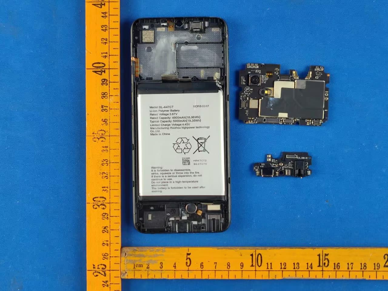
2AEPISILVERC
Jun 28, 2023Smart Phone
Equipment Class
DSS - Part 15 Spread Spectrum Transmitter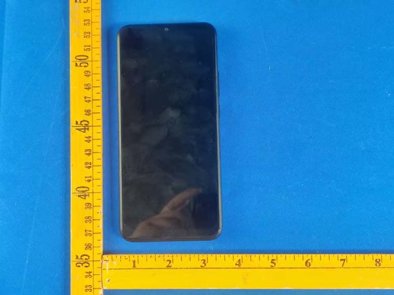
2AEPIBLACKCPRO
May 21, 2023Smart Phone
Equipment Class
DSS - Part 15 Spread Spectrum Transmitter