2AEWY-NL04ANanoleaf BLE&Thread-Matter module
NANOGRID LIMITED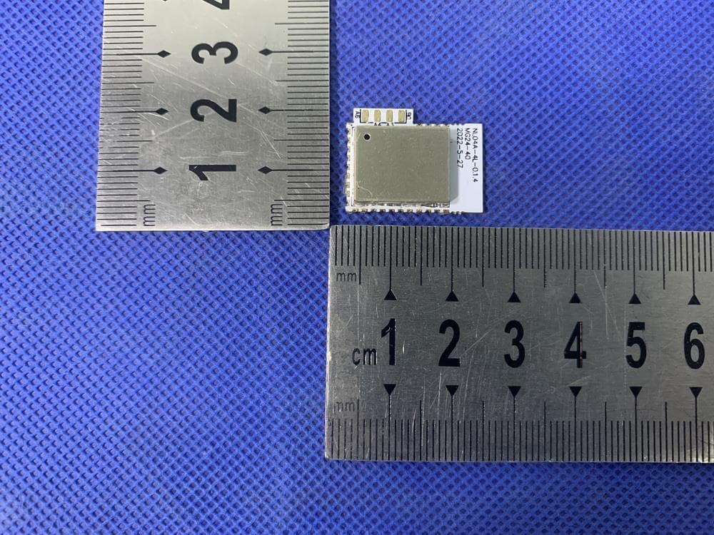
Click to zoom
Application Details
- Equipment Class
- DTS - Digital Transmission System
- Date of Grant
- Aug 14, 2022
- Application Purpose
- Original Equipment
- Date of Application
- Aug 14, 2022
- Equipment Note
- Nanoleaf BLE&Thread-Matter module
- Frequency Range
- 2405.00000000 - 2480.00000000
- Company
- NANOGRID LIMITED
- Country
- Hong Kong
Documents & Files
Document Text
Text extracted from the exhibit documents filed with the FCC. Open a document above to read the original.
Users Manual
NL04A Datasheet Includes: NL04A Version 1.0 Nanoleaf Copyright © 2022 https://nanoleaf.cn/ About This Guide This document provides introduction to the specifications of NL01A and hardware. Release Notes Date Version Release notes 2022.07 V1.0 First release. Documentation Change Notification Nanoleaf provides email notifications to keep customers updated on changes to technical documentation. Please subscribe at mailto:[email protected]. Certification Download certificates for Nanoleaf products from mailto:[email protected] cations of NL04A and ha 1. Overview NL04A is EFR32MG24-based modules developed by Nanoleaf. Table 1-1. NL04A Core EFR32MG24 Antenna Onboard antenna Schematics See Figure 5-1 for details. Note: For mo re information on EFR32MG24, please refer to EFR32MG24 Datasheet. Table 1-2. NL04A Specifications Categories Items Specifications Certification RF certification SRRC, FCC, CE (RED), IC, NCC, KCC, TELEC (MIC) **(All Ongoing) Green certification RoHS, REACH Test Reliablity HTOL/HTSL/uHAST/TCT/ESD BLE Modulation Type GFSK Frequency range 2402 MHz ~ 2480 MHz Thread Modulation Type QPSK Frequency range 2405 MHz ~ 2480 MHz Hardware Peripheral interface ADC/GPIO/I²C/I²S/SPI/UART GPIO/PWM Operating voltage 2.7 V ~ 3.8 V Operating current Average: 10 mA Minimum current delivered by power supply 200 mA Operating temperature range -40 °C ~ 85 °C Storage temperature -40 °C ~ 85 °C Module NL04A (17.50 ± 0.10) x (22.50 ± 0.10) x (3.20 ± 0.10) . Dimensions (unit: mm) 本模块为完整独立操作发射模块,CMIIT ID: 如产品只使用本无线发射模块时,应在最终产品上标志本模块的CMIIT ID码。 1. Overview Categories Items Specifications Software External interface - Moisture sensitivity level Level 3 Firmware upgrade OTA (via network)/Download and write via host Software development Supports Cloud Server Development/SDK for custom firmware development User configuration Cloud Server, Android/iOS app 2. Pin Description 2.Pin Description Figure 2-1 shows the pin distribution of the NL04A. Figure 2-1. NL04 Pin Layout (Top View) Note: All Gnd Pin should connect to Fatherboard GND NL04A have 29 pins. Please see the pin definitions in Table 2-1. Table 2-1. NL04A Pin Definitions 3. Functional Description 3.Functional Description 3.1. Core The ARM Cortex-M processor includes a 32-bit RISC processor integrating the following features and tasks in the system: •ARM Cortex-M33 RISC processor achieving 1.50 Dhrystone MIPS/MHz •ARM TrustZone security technology •Embedded Trace Macrocell (ETM) for real-time trace and debug •Up to 1024 kB flash program memory •Up to 256 kB RAM data memory •Configuration and event handling of all modules •2-pin Serial-Wire debug interface 3.2 . Memory 3.2.1. SPI Flash NL04A currently integrate a 8-Mbit SPI flash and also supports these SPI modes: Standard SPI, DIO (Dual I/O), DOUT (Dual Output), QIO (Quad I/O) and QOUT (Quad Output). Up to 1536 kB flash program memory 4. Electrical Characteristics 4.Electrical Characteristics Note: Unless otherwise specified, measurements are based on VDD = 3.3 V, TA = 25 °C. 4.1. Electrical Characteristics Table 4-1. Electrical Characteristics 4.2. RF Radio Table 4-2. RF Radio Characteristics MODE Description Min Typ Max Unit Thread Radio, 250 kbps O- QPSK DSSS Input frequency 2405 -2480MHz Output Power -- 10dBm Sensitivity - - 104.5 -dBm Bluetooth® Low Energy Radio GFSK Input frequency 2402 -2480MHz Output Power -- 10dBm Sensitivity@1 Mbps GFSK --94.4-dBm Parameter Symbol Min Typ Max Unit Operating temperature --4020 85 °C Maximum soldering temperature (Condition: IPC/JEDEC J-STD-020) -- -260 °C Supply voltage VDD 2.7 3.3 3.8 V Input logic level low V IL - - 0.3*IOVDD V Input logic level high V IH 0.7*IOVDD -- V Output logic level low V OL - - 0.2*IOVDD V Output logic level high V OH 0.8*IOVDD -- V 4. Electrical Characteristics 4.3. Power Consumption The following power consumption data were obtained from the tests with a 3.3 V power supply and a voltage stabilizer, in 25 °C ambient temperature. All data are based on 50% duty cycle in continuous transmission mode. Table 4-3. Power Consumption MODE Specs Min Typ Max Unit Thread Radio, 250 kbps O-QPSK DSSS Thread Radio, Active RX Mode -9.4-mA Active TX Mode @ 0 dBm -9.3-mA Active TX Mode @ 10 dBm -33.8-mA Bluetooth® Low Energy Radio Thread Radio, Active RX Mode -8.8-mA Active TX Mode @ 0 dBm -9.3-mA Active TX Mode @ 10 dBm -33.8-mA 4.4. Reflow Profile 250 200 100 50 25 0 0 100 250 Figure 4-1. NL04A Reflow Profile Note: Solder the module in a single reflow. If the PCBA requires multiple reflows, place the module on the PCB during the final reflow. 4.5. Electrostatic Discharge Table 4-4. Electrostatic Discharge Parameters Peak Temp. 235 ~ 250°C Preheating 150 ~ 200°C zone 60 ~ 120s Reflowzone >217°C 60 ~ 90s Cooling zone Ramp-up zone Soldering time > 30s Time (sec.) Name Symb Temperature: 23 ± 5 °C Based on ANSI/ESDA/JEDEC JS - 001 - 2014 2 2000 V Electrostatic Discharge (Charged - Device Model) 217 -1 ~ -5°C/s 1 ~ 3°C/s 50 150 200 Ramp-up zone — Temp.: <150°C Time: 60 ~ 90s Ramp-up rate: 1 ~ 3°C/s Preheating zone — Temp.: 150 ~ 200°C Time: 60 ~ 120s Ramp-up rate: 0.3 ~ 0.8°C/s Reflow zone — Temp.: >217°C 7LPH□@60 ~ 90s; Peak Temp.: 235 ~ 250°C (<245°C recommended) Time: 30 ~70s Cooling zone — Peak Temp. ~ 180°C Ramp-down rate: -1 ~ -5°C/s Solder — Sn&Ag&Cu Lead-free solder (SAC305) ol Reference LevelMaxUnit Elect rostatic Discharge (Human - Body Model) VESD (HBM) Temperature: 23 ± 5 °C Based on JEDEC EIA/JESD22 - C101F C2 500 VESD (CDM) T em peratu r e ( °C ) NCC警語:取得審驗證明之低功率射頻器材,非經核准,公司、商號或使用者均不得擅自變更頻率、加大功率 或變更原設計之特性及功能。 低功率射頻器材之使用不得影響飛航安全及干擾合法通信;經發現有干擾現象時,應立即停用,並改善至無干 擾時方得繼續使用。 前述合法通信,指依電信管理法規定作業之無線電通信。 低功率射頻器材須忍受合法通信或工業、科學及醫療用電波輻射性電機設備之干擾。 FCC Caution: Any changes or modifications not expressly approved by the party responsible for compliance could void the user’s authority to operate this device. This device complies with Part 15 of the FCC Rules. Operation is subject to the following two conditions: (1) This device may not cause harmfu…
Text truncated - open the document above for the full version.
Cover Letter(s)
NANOGRID LIMITED Request for Modular/Limited Modular Approval Date: August 10, 2022 Subject: Manufacturer’s Declaration for ☒ - Modular Approval ☐ - Split Modular Approval ☐ - Limited Modular Approval ☐ - Limited Split Modular Approval Confidentiality Request for: ______2AEWY-NL04A ______ 8 Basic Requirements – FCC Part 15.212(a)(1) For Items Marked “NO(*)”, the Limited Module Description Must be Filled Out on the Following Pages Modular Approval Requirement Requirement Met 1. The modular transmitter must have its own RF shielding. This is intended to ensure that the module does not have to rely upon the shielding provided by the device into which it is installed in order for all modular transmitter emissions to comply with FCC limits. It is also intended to prevent coupling between the RF circuitry of the module and any wires or circuits in the device into which the module is installed. Such coupling may result in non-compliant operation. The physical crystal and tuning capacitors may be located external to the shielded radio elements. 15.212(a)(1)(i) ☒ - YES ☐ - NO(*) 2. The modular transmitter must have buffered modulation/data inputs (if such inputs are provided) to ensure that the module will comply with FCC requirements under conditions of excessive data rates or over-modulation. 15.212(a)(1)(ii) ☒ - YES ☐ - NO(*) 3. The modular transmitter must have its own power supply regulation on the module. This is intended to ensure that the module will comply with FCC requirements regardless of the design of the power supplying circuitry in the device into which the module is installed. 15.212(a)(1)(iii) ☒ - YES ☐ - NO(*) 4. The modular transmitter must comply with the antenna and transmission system requirements of §§ 15.203, 15.204(b), 15.204(c), 15.212(a), and 2.929(b). The antenna must either be permanently attached or employ a ‘‘unique’’ antenna coupler (at all connections between the module and the antenna, including the cable). The ‘‘professional installation’’ provision of § 15.203 is not applicable to modules but can apply to limited modular approvals under paragraph 15.212(b). 15.212(a)(1)(iv) ☒ - YES ☐ - NO(*) 5. The modular transmitter must be tested in a stand-alone configuration, i.e., the module must not be inside another device during testing. This is intended to demonstrate that the module is capable of complying with Part 15 emission limits regardless of the device into which it is eventually installed. Unless the transmitter module will be battery powered, it must comply with the AC line conducted requirements found in Section 15.207. AC or DC power lines and data input/output lines connected to the module must not contain ferrites, unless they will be marketed with the module (see Section 15.27(a)). The length of these lines shall be length typical of actual use or, if that length is unknown, at least 10 centimeters to insure that there is no coupling between the case of the module and supporting equipment. Any accessories, peripherals, or support equipment connected to the module during testing shall be unmodified or commercially available (see Section 15.31(i)). 15.212(a)(1)(v) ☒ - YES ☐ - NO(*) NANOGRID LIMITED Modular Approval Requirement Requirement Met 6. The modular transmitter must be labeled with its own FCC ID number, or use an electron display (see KDB Publication 784748). If using a permanently affixed label with its own FCC ID number, if the FCC ID is not visible when the module is installed inside another device, then the outside of the device into which the module is installed must also display a label referring to the enclosed module. This exterior label can use wording such as the following: “Contains Transmitter Module FCC ID: XYZMODEL1” or “Contains FCC ID: XYZMODEL1.” Any similar wording that expresses the same meaning may be used. The Grantee may either provide such a label, an example of which must be included in the application for equipment authorization, or, must provide adequate instructions along with the module which explain this requirement. In the latter case, a copy of these instructions must be included in the application for equipment authorization. If the modular transmitter uses an electronic display of the FCC identification number, the information must be readily accessible and visible on the modular transmitter or on the device in which it is installed. If the module is installed inside another device, then the outside of the device into which the module is installed must display a label referring to the enclosed module. This exterior label can use wording such as the following: “Contains FCC certified transmitter module(s).” Any similar wording that expresses the same meaning may be used. The user manual must include instructions on how to access the electronic display. A copy of these instructions must be included in the application for equipment authorization. 15.212(a)(1)(vi) ☒ - YES ☐ - NO(*) 7. The modular transmitter must comply with all specific rule or operating requirements applicable to the transmitter, including all the conditions provided in the integration instructions by the grantee. A copy of these instructions must be included in the application for equipment authorization. For example, there are very strict operational and timing requirements that must be met before a transmitter is authorized for operation under Section 15.231. For instance, data transmission is prohibited, except for operation under Section 15.231(e), in which case there are separate field strength level and timing requirements. Compliance with these requirements must be assured. 15.212(a)(1)(vii) ☒ - YES ☐ - NO(*) 8. The modular transmitter must comply with any applicable RF exposure requirements. For example, FCC Rules in Sections 2.1091, 2.1093 and specific Sections of Part 15, including 15.319(i), 15.407(f), 15.253(f) and 15.255(g), require that Unlicensed PCS, UNII and millimeter wave devices perform routine environmental evaluation for RF Ex…
Text truncated - open the document above for the full version.
Cover Letter(s)
NANOGRID LIMITED 2021-08-01 Eurofins Electrical and Electronic Testing NA, Inc. 914 West Patapsco Avenue Baltimore, MD 21230 RE: CONFIDENTIALITY REQUEST FOR (EUT Name: Nanoleaf BLE&Thread-Matter module /Model: NL04A /FCCID: 2AEWY-NL04A) To Whom It May Concern: This letter serves as an official request for confidentiality under sections 0.457 and 0.459 of CFR 47. We have requested that the (Block Diagram ,Operational Description,Schematics) required to be submitted with this application be permanently withheld from public review. The above materials contain trade secrets and proprietary information not customarily released to the public. The public disclosure of these materials may be harmful to the applicant and provide unjustified benefits to its competitors. Please contact me if there is any information you may need. Sincerely, Christian Yan COO NANOGRID LIMITED ROOM 1405, 135 BONHAM STRAND TRADE CENTRE, 135 BONHAM STRAND, SHEUNG WAN, Hong Kong
Cover Letter(s)
NANOGRID LIMITED 2022-08-02 Eurofins Electrical and Electronic Testing NA, Inc. 914 West Patapsco Avenue Baltimore, MD 21230 RE: LETTER OF AGENT AUTHORIZATION To Whom It May Concern: We, the undersigned, hereby authorize DongGuan Anci Electronic Technology Co., Ltd. to act on our behalf in all matters relating to application for equipment authorization, including the signing of all documents relating to these matters. We also hereby certify that no party to the application authorized hereunder is subject to the denial of benefits, including FCC benefits, pursuant to Section 5301 of the Anti-Drug Abuse Act of 1988, 21 U.S.C.853(a). This agreement expires one year from the current date. Sincerely, Christian Yan COO NANOGRID LIMITED ROOM 1405, 135 BONHAM STRAND TRADE CENTRE, 135 BONHAM STRAND, SHEUNG WAN, Hong Kong
ID Label/Location Info
Label:silk screen Label location: Product:Nanoleaf BLE&Thread-Matter module Model:NL04A Date Code: FCC ID: 2AEWY-NL04A IC: 20489-NL04A
Internal Photos
ANT
RF Exposure Info
RF EXPOSURE EVALUATION EUT Specification EUT Nanoleaf BLE&Thread-Matter module Model Number NL04A FCC ID 2AEWY-NL04A Antenna gain (Max) 2.15dBi Operation Frequency BLE:2.402-2.480GHz Thread: 2.405-2.480GHz Input Rating DC 2.7V~3.8V Max. output power BLE: 8.71dBm(0.0074W) Thread: 9.1dBm(0.0081W) Test Requirement: According to FCC 1.1310: The criteria listed in the following table shall be used to evaluate the environment impact of human exposure to radio frequency(RF) Radiation as specified in §1.1307(b) Limits for Maximum Permissible Exposure (MPE) Frequency Range(MHz) Electric Field Strength(V/m) Magnetic Field Strength(A/m) Power Density(mW/cm 2 ) Average Time (A) Limits for Occupational/Control Exposures 300-1500 -- -- F/300 6 1500-100000 -- -- 5 6 (B) Limits for General Population/Uncontrol Exposures 300-1500 -- -- F/1500 6 1500-100000 -- -- 1 30 11.1 Friis transmission formula: Pd= (Pout*G)\ (4*pi*R 2 ) Where Pd= Power density in mW/cm 2 Pout=output power to antenna in mW G= Numeric gain of the antenna relative to isotropic antenna Pi=3.1416 R=20cm, distance between observation point and center of the radiator in cm Pd the limit of MPE, 1mW/cm 2 . If we know the maximum gain of the nd total power input to the antenna, through the calculation, we will know the distance where the MPE limit is reached. 11.2 Measurement Result Antenna gain: 2.15 dBi BLE: Mode Channe l Freq. (MHz) Measu red power (dBm) Tune- up power (dBm) Max tune-up power (dBm) Antenna Gain (Numeri c) Evaluation result (mW/cm2 ) Power density Limits (mW/cm2 ) GFSK 2402 8.09 8±1 9 1.641 0.002593 1 GFSK 2440 8.45 8±1 9 1.641 0.003265 1 GFSK 2480 8.71 9±1 10 1.641 0.003265 1 Thread: Mode Channe l Freq. (MHz) Measu red power (dBm) Tune- up power (dBm) Max tune-up power (dBm) Antenna Gain (Numeri c) Evaluation result (mW/cm2 ) Power density Limits (mW/cm2 ) O-QPSK 2405 8.48 8±1 9 1.641 0.002593 1 O-QPSK 2440 8.80 9±1 10 1.641 0.003265 1 O-QPSK 2480 9.10 9±1 10 1.641 0.003265 1 Signature: Tiger Xu Date: 2022-08-02
Test Report
Report No.: E01A22070224F00101 1 of 48 DongGuan Anci Electronic Technology Co., Ltd 1-2 Floor, Building A, No.11, Headquarters 2 Road, Songshan Lake Hi-tech Industrial Development Zone, Dongguan City, Guangdong Pr., China. Phone: 86-769- 8507 5888; Fax: 86-769- 8507 5898 E-mail: [email protected] Rev. 1.0 ELECTROMAGNETIC EMISSIONS COMPLIANCE REPORT INTENTIONAL RADIATOR CERTIFICATION TO FCC PART 15 SUBPART C REQUIREMENT OF Nanoleaf BLE&Thread-Matter module Model No.: NL04A Trademark: Nanoleaf FCC ID: 2AEWY-NL04A Report No.: E01A22070224F00101 Issue Date: August 08, 2022 Prepared for NANOGRID LIMITED ROOM 1405, 135 BONHAM STRAND TRADE CENTRE, 135 BONHAM STRAND, SHEUNG WAN, Hong Kong Prepared by Dong Guan Anci Electronic Technology Co., Ltd. 1-2 Floor, Building A, No.11, Headquarters 2 Road, Songshan, Lake Hi-tech Industrial Development Zone, Dongguan City, Guangdong Pr., China. This report shall not be reproduced, except in full, without the written approval of Dong Guan Anci Electronic Technology Co., Ltd. Report No.: E01A22070224F00101 2 of 48 TRF No. FCC Part 15.247/A Ver.1.0 VERIFICATION OF COMPLIANCE Applicant: NANOGRID LIMITED ROOM 1405, 135 BONHAM STRAND TRADE CENTRE, 135 BONHAM STRAND, SHEUNG WAN, Hong Kong Manufacturer: NANOGRID LIMITED ROOM 1405, 135 BONHAM STRAND TRADE CENTRE, 135 BONHAM STRAND, SHEUNG WAN, Hong Kong Product Description: Nanoleaf BLE&Thread-Matter module Trade Mark: Nanoleaf Model Number: NL04A We hereby certify that: The above equipment was tested by Dong Guan Anci Electronic Technology Co., Ltd. The test data, data evaluation, test procedures, and equipment configurations shown in this report were made in accordance with the procedures given in ANSI C63.10-2013 and the energy emitted by the sample EUT tested as described in this report is in compliance with conducted and radiated emission limits of FCC Rules Part 15.247(2022). Date of Test : July 13, 2022 to July 28, 2022 Prepared by : Tomas Yang/Editor Approved & Authorized Signer : Tiger Xu/ Supervisor Report No.: E01A22070224F00101 3 of 48 TRF No. FCC Part 15.247/A Ver.1.0 Modified Information Version Summary Revision Date Report No. Ver.1.0 Original Report / E01A22070224F00101 Report No.: E01A22070224F00101 4 of 48 TRF No. FCC Part 15.247/A Ver.1.0 Table of Contents 1. GENERAL INFORMATION ............................................................................................................ 6 1.1 PRODUCT DESCRIPTION .............................................................................................................. 6 1.2 TEST METHODOLOGY .................................................................................................................. 6 2. TEST FACILITY ................................................................................................................................ 7 3. DESCRIPTION OF TEST MODES ................................................................................................ 8 4. SUMMARY OF TEST RESULTS ................................................................................................. 10 6DB BANDWIDTH MEASUREMENT ............................................................................................. 10 5. TEST SYSTEM UNCERTAINTY .................................................................................................. 11 6. CONDUCTED EMISSIONS TEST ............................................................................................... 12 6.1MEASUREMENT PROCEDURE: ..................................................................................................... 12 6.2TEST SET-UP (BLOCK DIAGRAM OF CONFIGURATION) ................................................................. 12 6.3MEASUREMENT EQUIPMENT USED: ............................................................................................. 12 6.4 CONDUCTED EMISSION LIMIT ..................................................................................................... 12 6.5 MEASUREMENT RESULT: ........................................................................................................... 13 7. RADIATED EMISSION TEST ....................................................................................................... 16 7.1MEASUREMENT PROCEDURE ...................................................................................................... 16 7.2TEST SET-UP (BLOCK DIAGRAM OF CONFIGURATION) ................................................................. 18 7.3MEASUREMENT EQUIPMENT USED: ............................................................................................. 19 7.4 RADIATED EMISSION LIMIT .......................................................................................................... 20 7.5 MEASUREMENT RESULT .......................................................................................................... 21 7.6 RADIATED MEASUREMENT PHOTOS: ........................................................................................... 27 8. 6DB BANDWIDTH MEASUREMENT ......................................................................................... 28 8.1MEASUREMENT PROCEDURE ...................................................................................................... 28 8.2TEST SET-UP (BLOCK DIAGRAM OF CONFIGURATION) ................................................................. 28 8.3 MEASUREMENT EQUIPMENT USED: ............................................................................................ 28 8.4 LIMIT ........................................................................................................................................ 28 8.5MEASUREMENT RESULTS: .......................................................................................................... 28 9. MAXIMUM PEAK OUTPUT POWER TEST .............................................................................. 29 9.1MEASUREMENT PROCEDURE ................................................…
Text truncated - open the document above for the full version.
Test Report
Report No.: E01A22070224F00201 1 of 46 TRF No. FCC Part 15.247/A Ver.1.0 ELECTROMAGNETIC EMISSIONS COMPLIANCE REPORT FCC PART 15 SUBPART C REQUIREMENT OF Nanoleaf BLE&Thread-Matter module Model No.: NL04A Trademark: Nanoleaf FCC ID: 2AEWY-NL04A Report No.: E01A22070224F00201 Issue Date: July 29, 2022 Prepared for NANOGRID LIMITED ROOM 1405, 135 BONHAM STRAND TRADE CENTRE, 135 BONHAM STRAND, SHEUNG WAN, Hong Kong Prepared by Dong Guan Anci Electronic Technology Co., Ltd. 1-2 Floor, Building A, No.11, Headquarters 2 Road, Songshan, Lake Hi-tech Industrial Development Zone, Dongguan City, Guangdong Pr., China. This report shall not be reproduced, except in full, without the written approval of Dong Guan Anci Electronic Technology Co., Ltd. Report No.: E01A22070224F00201 2 of 46 TRF No. FCC Part 15.247/A Ver.1.0 VERIFICATION OF COMPLIANCE Applicant: NANOGRID LIMITED ROOM 1405, 135 BONHAM STRAND TRADE CENTRE, 135 BONHAM STRAND, SHEUNG WAN, Hong Kong Manufacturer: NANOGRID LIMITED ROOM 1405, 135 BONHAM STRAND TRADE CENTRE, 135 BONHAM STRAND, SHEUNG WAN, Hong Kong Product Description: Nanoleaf BLE&Thread-Matter module Trade Mark: Nanoleaf Model Number: NL04A We hereby certify that: The above equipment was tested by Dong Guan Anci Electronic Technology Co., Ltd. The test data, data evaluation, test procedures, and equipment configurations shown in this report were made in accordance with the procedures given in ANSI C63.10-2013 and the energy emitted by the sample EUT tested as described in this report is in compliance with conducted and radiated emission limits of FCC Rules Part 15.247(2022). Date of Test : July 13, 2022 to July 28, 2022 Prepared by : Tomas Yang/Editor Approved & Authorized Signer : Tiger Xu/ Supervisor Report No.: E01A22070224F00201 3 of 46 TRF No. FCC Part 15.247/A Ver.1.0 Modified Information Version Summary Revision Date Report No. Ver.1.0 Original Report / E01A22070224F00201 Report No.: E01A22070224F00201 4 of 46 TRF No. FCC Part 15.247/A Ver.1.0 Table of Contents 1. GENERAL INFORMATION ............................................................................................................ 6 1.1 PRODUCT DESCRIPTION .............................................................................................................. 6 1.2 TEST METHODOLOGY .................................................................................................................. 6 2. TEST FACILITY ................................................................................................................................ 7 3. DESCRIPTION OF TEST MODES ................................................................................................ 8 4. SUMMARY OF TEST RESULTS ................................................................................................. 10 5. TEST SYSTEM UNCERTAINTY .................................................................................................. 11 6. CONDUCTED EMISSIONS TEST ............................................................................................... 12 6.1MEASUREMENT PROCEDURE: ..................................................................................................... 12 6.2TEST SET-UP (BLOCK DIAGRAM OF CONFIGURATION) ................................................................. 12 6.3MEASUREMENT EQUIPMENT USED: ............................................................................................. 12 6.4 CONDUCTED EMISSION LIMIT ..................................................................................................... 12 6.5 MEASUREMENT RESULT: ........................................................................................................... 13 6.5 CONDUCTED MEASUREMENT PHOTOS: ....................................................................................... 15 7. RADIATED EMISSION TEST ....................................................................................................... 16 7.1MEASUREMENT PROCEDURE ...................................................................................................... 16 7.2TEST SET-UP (BLOCK DIAGRAM OF CONFIGURATION) ................................................................. 18 7.3MEASUREMENT EQUIPMENT USED: ............................................................................................. 19 7.4 RADIATED EMISSION LIMIT .......................................................................................................... 20 7.5 MEASUREMENT RESULT .......................................................................................................... 21 7.6 RADIATED MEASUREMENT PHOTOS: ........................................................................................... 26 8. 6DB BANDWIDTH MEASUREMENT ......................................................................................... 27 8.1MEASUREMENT PROCEDURE ...................................................................................................... 27 8.2TEST SET-UP (BLOCK DIAGRAM OF CONFIGURATION) ................................................................. 27 8.3 MEASUREMENT EQUIPMENT USED: ............................................................................................ 27 8.4 LIMIT ........................................................................................................................................ 27 8.5MEASUREMENT RESULTS: .......................................................................................................... 27 9. MAXIMUM PEAK OUTPUT POWER TEST .............................................................................. 28 9.1MEASUREMENT PROCEDURE ...................................................................................................... 30 9.2TEST SET-UP (BLOCK DIAGRAM OF CONFIGURATION) ................................................................. 30 9.3 MEASUREMENT EQUIPMENT USED: .............................................................…
Text truncated - open the document above for the full version.
Contact Information
Applicant
Christian Yan
Technical Contact
DongGuan Anci Electronic Technology Co., Ltd.Kingbo Hu
[email protected]86-769- 8507 5888
1-2 Floor, Building A, No. 11, Headquarters 2 Road · Dongguan, Guangdong, · China
Test Firm
Guangdong GTG Testing Technology Co., Ltd.Kingbo Hu
[email protected]86-769- 8507 5888
Technical Specifications
| # | Rule Parts | Frequency Range | Power Output |
|---|---|---|---|
| 2 | 15C | 2.40 GHz - 2.48 GHz | 8.10 mW |
Other Applications from NANOGRID LIMITED
2AEWY-NL44
Aug 18, 2024Nanoleaf Sense+ Smart Button
Equipment Class
DTS - Digital Transmission System
2AEWY-NL06A
Jun 25, 2024Nanoleaf WIFI module
Equipment Class
DTS - Digital Transmission System
2AEWY-NL69
Aug 23, 2023Strip Light with Bluetooth, Thread and Wi-Fi
Equipment Class
DTS - Digital Transmission System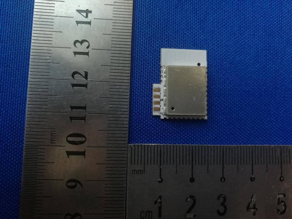
2AEWY-NL01A
Mar 01, 2021Nanoleaf Esseantials Module
Equipment Class
DXX - Part 15 Low Power Communication Device Transmitter
2AEWY-NL55
Sep 10, 2020Nanoleaf Essentials Light Strips
Equipment Class
DXX - Part 15 Low Power Communication Device Transmitter