2AFGR-APS2530PZigBee Module
Altenergy Power System Inc.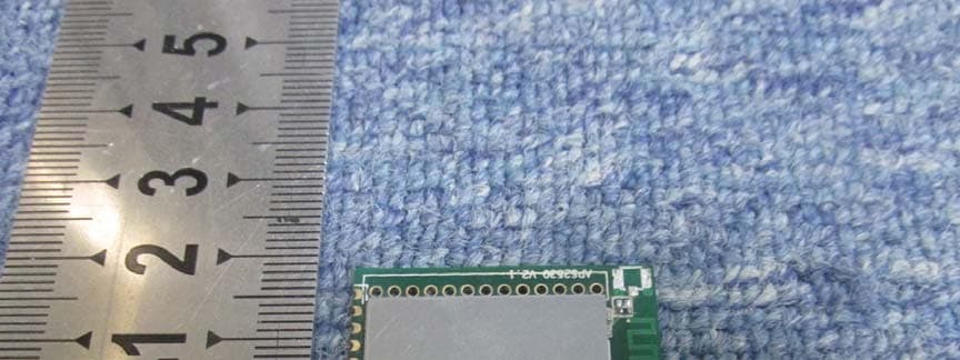
Click to zoom
Application Details
- Equipment Class
- DTS - Digital Transmission System
- Date of Grant
- Sep 01, 2015
- Application Purpose
- Original Equipment
- Date of Application
- Sep 01, 2015
- Equipment Note
- ZigBee Module
- Frequency Range
- 2405.00000000 - 2480.00000000
- Company
- Altenergy Power System Inc.
- Country
- China
Documents & Files
Document Text
Text extracted from the exhibit documents filed with the FCC. Open a document above to read the original.
Users Manual
User Manual for APS2530P The model used ZigBee PRO protocol to send RF signals for device communication. The model can be used after pairing with a dedicated device which was installed with a receiver dongle. APS2530P was used as a dongle which need to be installed in customer’s device. It offers UART to communicate with customer’s device according predefined protocol. 1: product figure (APS2530P) 2: Technical specifications RF operating frequency: 2405MHz ~ 2480MHz Reference frequency: 2.400GHz Channel spacing: 5MHz Channel wide:2MHz Modulation method: OQPSK Communication rate: 250Kbps Output power: 6.85dBm Communication mechanism: applied ZigBee frequency hopping mechanism, passively frequency hopping. Average operating current:<10mA Operating voltage:2V-3.6V Max remitting current: 20mA Max rate:250Kbit/s Receiving sensitivity: -95dbm Receiving current:<24mA Normal operating receiving distance: 100M 3: Warning - Do not disassemble, repair, modify or replace the remote control Unit or any of its components. EF Radiation Exposure and Hazard Statement: - To ensure compliance with FCC RF exposure requirement, this device must be installed in a location such that antenna of the device will b greater than 20cm away from all persons. Using higher gain antennas and types of antennas not covered under the FCC certification of this product is not allowed. Installers of the radio and end users of the product must adhere to installation instructions provided in this manual. This transmitter must not be co-located or operating in conjunction with any other antenna or transmitter. - Non-modification Statement: Use only the whip antenna supplied by the manufacturer when operating this device. Unauthorized antennas, modifications, or attachments, could damage the device and violate FCC regulations. Any changes or modifications not expressly approved by the party responsible for compliance could void the user’s authority to operate this equipment. - Please comply with the national and international flight safety regulations when using device during your flight trip. - Operating for this product is between -40°C~65°C. This device complies with part 15 of the FCC Rules. Operation is subject to the following two conditions: (1) This device may not cause harmful interference, and (2) this device must accept any interference received, including interference that may cause undesired operation - User manual of the end product: In the user manual of the end product, the end user has to be informed that the equipment complies with FCC radio-frequency exposure guidelines set forth for an uncontrolled environment. The end user has to also be informed that any changes or modifications not expressly approved by the manufacturer could void the user's authority to operate this equipment. If the size of the end product is smaller than 8x10cm, then additional FCC part 15.19 statement is required to be available in the user manual: This device complies with Part 15 of FCC rules. Operation is subject to the following two conditions: (1) this device may not cause harmful interference and (2) this device must accept any interference received, including interference that may cause undesired operation. Important Note: In the event that these conditions cannot be met, such as the certain laptop configuration or co-location with another transmitter, and then this FCC authorization is no longer considered valid and the FCC ID cannot be used on the final product any more. In these circumstances, the OEM integrator will be responsible for re-evaluating the end product and obtaining a separate FCC authorization End product labeling: The transmitter module is authorized only for use in device where the antenna may be installed such that 20cm may be maintained between the antenna and users. The final end product must be labeled in a visible area with the following: “Contains FCC ID: 2AFGR- APS2530P”. Manual information to the end user: The OEM integrator has to be aware not to provide information to the end user regarding how to install or remove this RF module in the user manual of the end product which integrates this module. The end user manual shall include all required regulatory information/warning statement as they are shown in this manual IC Radiation Exposure Statement: This module complies with the relevant IC radiation exposure limits set forth for an uncontrolled environment. This module should be installed and operated with the minimum distance 20cm between the radiator and the end user. Ce module est conforme aux limites IC d'exposition aux radiations pertinentes énoncées pour un envi incontrôlée. Ce module doit être installé et utilisé avec le 20cm de distance minimale entre le radiateur et l'utilisateur final Important Note: In the event that these conditions cannot be met, such as the certain laptop configuration or co-location with another transmitter, and then the IC authorization is no longer considered valid and the IC number cannot be used on the final product any more. In these circumstances, the OEM integrator will be responsible for re-evaluating the end product and obtaining a separate IC authorization. Dans le cas où ces conditions ne peuvent être remplies, telles que la configuration de l'ordinateur portable ou certains co-localisation avec un autre émetteur, et puis l'autorisation de circuit intégré est plus considéré comme valide et le nombre IC peut pas être utilisé sur le produit final plus. Dans ces circonstances, l'intégrateur OEM sera chargé de réévaluer le produit final et l'obtention d'une autorisation IC séparée. End product labeling: The transmitter module is authorized only for use in device where the antenna may be installed such that 20cm may be maintained between the antenna and users. The final end product must be labeled in a visible area with the following: “Contains IC: 20481- APS2530P ”. Le module émetteur est autorisé uniquement pour une utilisation dans le dispositif où l'antenne peu…
Text truncated - open the document above for the full version.
Cover Letter(s)
Altenergy Power System Inc. 2015-8-4 Federal Communications Commission Authorization and Evaluation Division FCC ID:2AFGR-APS2530P Confidentiality Request Pursuant to Sections 0.457 and 0.459 of the Commission’s Rules, the applicant hereby requests confidential treatment of information applied this application as outlined below: 1. Block Diagram 2. Circuit Diagram 3. Operational Description 4. BOM The above materials contain trade secrets and proprietary information not customarily released to the public. The public disclosure of these matters might be harmful to the applicant and provide unjustified benefits to its competitors. The Applicant understands that pursuant to Rule 0.457, disclosure of this Application and all accompanying documentation will not be made before the date of the Grant for this application Sincerely, Kevin Lu Signature Name/Title: Kevin Lu/ engineer Applicant: Altenergy Power System Inc. ADDRESS: No.1, Yatai Road, Jiaxing Zhejiang 314050 P.R. China TEL: 0573-83986309 FAX: 0573-83986966 Email: [email protected]
Cover Letter(s)
Applicant/Grantee Altenergy Power System Inc. FCC ID: 2AFGR-APS2530P Section 15.212 Modular Transmitters Request for Modular Approval Request for Limited Modular Approval Requirements EUT Conditions Comply (Y/N) Single Modular Approval Requirements 1 The radio elements of the modular transmitter must have their own shielding. The physical crystal and tuning capacitors may be located external to the shielded radio elements. There is its own shielding on this module, please refer to the External Photo for the reference Y 2 The modular transmitter must have buffered modulation/data inputs (if such inputs are provided) to ensure that the module will comply with Part 15 requirements under conditions of excessive data rates or over-modulation. The module has the buffered modulation/data input(s) function which is controlled by the component CC2530(U1) Y 3 The modular transmitter must have its own power supply regulation. This module has its own power supply regulation which is controlled by the component CC2530(U1) Y 4 The modular transmitter must comply with the antenna and transmission system requirements of Sections 15.203, 15.204(b) and 15.204(c). The antenna must either be permanently attached or employ a “unique” antenna coupler (at all connections between the module and the antenna, including the cable). The “professional installation” provision of Section 15.203 is not applicable to modules but can apply to limited modular approvals under paragraph (b) of this section. The antenna type of this module is PCB which could comply with the antenna requirement Y 5 The modular transmitter must be tested in a stand-alone configuration, i.e., the module must not be inside another device during testing for compliance with Part 15 requirements. Unless the transmitter module will be battery powered, it must comply with the AC line conducted requirements found in Section 15.207. AC or DC power lines and data input/output lines connected to the module must not contain ferrites, unless they will be marketed with the module (see Section 15.27(a)). The length of these lines shall be the length typical of actual use or, if that length is unknown, at least 10 centimeters to insure that there is no coupling between This EUT is evaluated under the stand- alone configuration, please refer to the Setup Photo for the reference Y the case of the module and supporting equipment. Any accessories, peripherals, or support equipment connected to the module during testing shall be unmodified and commercially available (see Section 15.31(i)). 6 The modular transmitter must be equipped with either a permanently affixed label or must be capable of electronically displaying its FCC identification number. (A) If using a permanently affixed label, the modular transmitter must be labeled with its own FCC identification number, and, if the FCC identification number is not visible when the module is installed inside another device, then the outside of the device into which the module is installed must also display a label referring to the enclosed module. This exterior label can use wording such as the following: “Contains Transmitter Module FCC ID: XYZMODEL1” or “Contains FCC ID: XYZMODEL1.” Any similar wording that expresses the same meaning may be used. The Grantee may either provide such a label, an example of which must be included in the application for equipment authorization, or, must provide adequate instructions along with the module which explain this requirement. In the latter case, a copy of these instructions must be included in the application for equipment authorization. (B) If the modular transmitter uses an electronic display of the FCC identification number, the information must be readily accessible and visible on the modular transmitter or on the device in which it is installed. If the module is installed inside another device, then the outside of the device into which the module is installed must display a label referring to the enclosed module. This exterior label can use wording such as the following: “Contains FCC certified transmitter module(s).” Any similar wording that expresses the same meaning may be used. The user manual must include instructions on how to access the electronic display. A copy of these instructions must be included in the application for equipment authorization. This module complies with the relevant labelling requirement, please refer to the Label and User Manual for the reference Y 7 The modular transmitter must comply with any specific rules or operating requirements that ordinarily apply to a complete transmitter and the manufacturer must provide adequate instructions along with the module to explain any such requirements. A copy of these instructions must be included in the The relevant required FCC rule has been fulfilled and all the instructions for the maintaining compliance have been clearly stated in the User Manual already. Y application for equipment authorization. 8 The modular transmitter must comply with any applicable RF exposure requirements in its final configuration. This module meets the relevant RF exposure requirement, a MPE report with the 20cm restricted distance is submitted Y A limited modular approval may be granted for single or split modular transmitters that do not comply with all of the above requirements, e.g., shielding, minimum signaling amplitude, buffered modulation/data inputs, or power supply regulation, if the manufacturer can demonstrate by alternative means in the application for equipment authorization that the modular transmitter meets all the applicable Part 15 requirements under the operating conditions in which the transmitter will be used. Limited modular approval also may be granted in those instances where compliance with RF exposure rules is demonstrated only for particular product configurations. The applicant for certification must state how control of the end product into which the module will be installed will be maintained …
Text truncated - open the document above for the full version.
External Photos
EUT Photo ANTENNA
Internal Photos
EUT Photo ANTENNA
Test Report
Report No.: SET2015-11565 CCIC-SET/T(00) Page 1 of 34 RF TEST REPORT Report No.: SET2015-11565 Product Name: Zigbee Module FCC ID: 2AFGR-APS2530P IC: 20481-APS2530P Model No. : APS2530P Applicant: Altenergy Power System Inc. Address: No.1, Yatai Road, Jiaxing Zhejiang 314050 P.R. China Dates of Testing: 07/15/2015 — 07/24/2015 Issued by: CCIC-SET Lab Location: Electronic Testing Building, Shahe Road, Xili, Nanshan District, Shenzhen, 518055, P. R. China Tel: 86 755 26627338 Fax: 86 755 26627238 This test report consists of 34 pages in total. It may be duplicated completely for legal use with the approval of the applicant. It should not be reproduced except in full, without the written approval of our laboratory. The client should not use it to claim product endorsement by CCIC-SET. The test results in the report only apply to the tested sample. The test report shall be invalid without all the signatures of testing engineers, reviewer and approver. Any objections must be raised to CCIC-SET within 20 days since the date when the report is received. It will not be taken into consideration beyond this limit. Report No.: SET2015-11565 CCIC-SET/T(00) Page 2 of 34 Test Report Product Name ...................... : Zigbee Module Brand Name ......................... : APsystems Trade Name .......................... : N/A Applicant .............................. : Altenergy Power System Inc. Applicant Address ............... : No.1, Yatai Road, Jiaxing Zhejiang 314050 P.R. China Manufacturer ........................ : Altenergy Power System Inc. Manufacturer Address ......... : No.1, Yatai Road, Jiaxing Zhejiang 314050 P.R. China Test Standards ..................... : 47 CFR Part 15 Subpart C:Radio Frequency Devices RSS-247 Issue 1, May 2015 Digital Transmission Systems (DTSs), Frequency Hopping Systems (FHSs) and Licence-Exempt Local Area Network (LE-LAN) Devices Test Result............................ : PASS Tested by ............................ : 2015.07.24 Lu Lei, Test Engineer Reviewed by ......................... : 2015.07.24 Zhu Qi, Senior Egineer Approved by ......................... : 2015.07.24 Wu Li’an,Manager Report No.: SET2015-11565 CCIC-SET/T(00) Page 3 of 34 TABLE OF CONTENTS RF TEST REPORT .............................................................................................................................. 1 1. GENERAL INFORMATION .................................................................................................... 4 1.1. EUT Description ....................................................................................................................... 4 1.2. Test Standards and Results ........................................................................................................ 5 1.3. Description of test modes .......................................................................................................... 6 1.4. Test environment and mode ...................................................................................................... 6 1.5. Test Facilities ............................................................................................................................ 7 2. 47 CFR PART 15C REQUIREMENTS .................................................................................... 8 2.1. Antenna requirement ................................................................................................................. 8 2.2. Output Power ............................................................................................................................ 9 2.3. Bandwidth ............................................................................................................................... 10 2.3.7. Conducted Band Edges and Spurious Emissions .................................................................... 14 2.4. Power spectral density (PSD) ................................................................................................. 19 2.5. Conducted Emission ............................................................................................................... 22 2.6. Radiated Band Edge and Spurious Emission .......................................................................... 26 3. LIST OF MEASURING EQUIPMENT ................................................................................. 34 Change History Issue Date Reason for change 1.0 2015.07.24 First edition Report No.: SET2015-11565 Page 4 of 34 1. General Information 1.1. EUT Description EUT Type Zigbee Hardware Version APS2530 V2.1 Software Version Inverter_V2.0.5 Power Supply 3.3V Temperature operating range -40~85°C EUT supports Radios application Zigbee Frequency Range 2405MHz~2480MHz Channel Number 16 Bit Rate of Transmitter 250 kbps Modulation Type O-QPSK Antenna Type PCB Antenna Antenna Gain 0.8dBi Note 1: The EUT is a Zigbee Module, it contain Zigbee Module operating at 2.4GHz ISM band; the frequencies allocated for the zigbee is F(MHz)=2405+5*(n-11) (11<=n<=26). The lowest, middle, highest channel numbers of the Zigbee Module used and tested in this report are separately 11 (2405MHz), 18(2440MHz) and 26 (2480MHz). Note 2: For a more detailed description, please refer to Specification or User’s Manual supplied by the applicant and/or manufacturer. Report No.: SET2015-11565 Page 5 of 34 1.2. Test Standards and Results The objective of the report is to perform testing according to 47 CFR Part 15 Subpart C for the EUT FCC Certification: No. Identity Document Title 1 47 CFR Part 15 Subpart C 2013 Radio Frequency Devices 2 ANSI C63.10 2013 American National Standard for Testing Unlicensed Wireless Devices 3 RSS-GEN: Issue 4,November 2014 General Requirements and Information for the Certification of Radio Apparatus 4 RSS-247 Issue 1, May 2015 Digital Transmission Systems (DTSs), Frequency Hopping Systems (FHSs) and Licence-Exempt Local Area Network (LE-LAN) Devices Test detailed items/section required by FCC rules an…
Text truncated - open the document above for the full version.
Test Setup Photos
Setup Photo
Contact Information
Applicant
Guofeng Jiang(Director)
Test Firm
CCIC-SETQi Zhu
Technical Specifications
| # | Rule Parts | Frequency Range | Power Output |
|---|---|---|---|
| 1 | 15C | 2.40 GHz - 2.48 GHz | 4.80 mW |
Other Applications from Altenergy Power System Inc.
2AFGR-APS2652D
Sep 30, 2025Zigbee module
Equipment Class
DTS - Digital Transmission System2AFGR-APSC3
Apr 11, 2024Aps-c3
Equipment Class
DTS - Digital Transmission System
2AFGRECUR
Jan 25, 2021Energy Communication Unit
Equipment Class
DTS - Digital Transmission System
2AFGR-APS2530H
Jun 22, 2020Zigbee module
Equipment Class
DTS - Digital Transmission System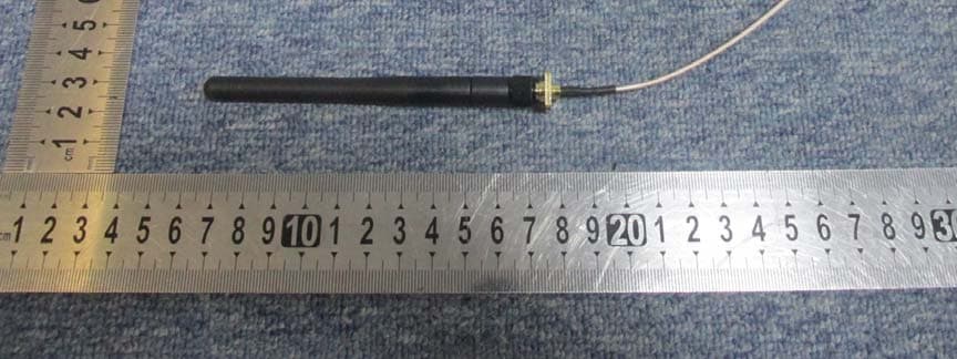
2AFGR-APS2530S
Sep 01, 2015ZigBee Module
Equipment Class
DTS - Digital Transmission System