2AG87ACM-DB-2MWi-Fi Radio Transceiver
Doodle Labs (SG) Pte Ltd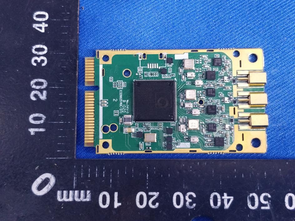
Click to zoom
Application Details
- Equipment Class
- DTS - Digital Transmission System
- Date of Grant
- Nov 05, 2020
- Application Purpose
- Original Equipment
- Date of Application
- Nov 05, 2020
- Equipment Note
- Wi-Fi Radio Transceiver
- Frequency Range
- 2412.00000000 - 2462.00000000
- Company
- Doodle Labs (SG) Pte Ltd
- Country
- Singapore
Documents & Files
Document Text
Text extracted from the exhibit documents filed with the FCC. Open a document above to read the original.
Users Manual
ACM-DB-2M Rugged/Military grade 2.4/ 2x2 MIMO Wi-Fi® Radio Transceivers Features •Qualcomm-Atheros QCA9890-BR4B Chipset with Extended Temperature Range •Up to 1.3 Gbps Throughput with 3x3 MIMO Technology •Calibrated High Power 2.4 GHz (29 dBm) afor Extended Range •802.11 Dynamic Frequency Selection (DFS) in AP and Client mode •Supported by OpenWRT and Ath10k Open-Source Driver •MiniPCIE Interface Installation and Usage The ACM-DB-2M has been FCC certified for indoor usage with Superbat 3-dBi rubber-duck antennas (WA2-1321-S02SP1-030 in the 5-GHz bands, and WA2-995-S02SP1-030 antennas in the 2.4GHz band). The ACM-DB-3 mates with a standard PCIE-mini slot and integrates with the Ath10k software driver which is pre- installed in Linux-based systems. TECHNICAL SPECIFICATIONS Model No. ACM-DB-2M(Rugged/Military Applications, 802.11ac) MAC Chipset QCA9890-BR4B with Extended Temperature range for Outdoor and Rugged models) Software Support Open Source Linux Driver ath10k OpenWRT (Wireless Router/Linux OS) Center Frequency Range 2.412 GHz ~ 2.484 GHz This varies by the regulatory domain Channel Bandwidth/(No. of Non- overlapping Channels)* 20/(27), 40/(13) and 80/(6) MHz channels (5.x GHz) 20/(3), and 40/(1) MHz channels (2.4 GHz) Radio Modulation (Auto Adjust) BPSK, QPSK, 16 QAM, 64 QAM and 256 QAM (5.x GHz – 11ac models) CCK, BPSK, QPSK, 16 QAM, and 64 QAM (2.4 GHz – 11ac models) Data Rates Supported 802.11n: MCS0-23 (5.x and 2.4 GHz) 802.11b/g: 1, 2, 5.5, 6, 9, 11, 12, 18, 24, 36, 48 and 54 Mbps (2.4 GHz) 802.11ac Wave 1 Capabilities ●Packet aggregation: A-MPDU (Tx/Rx), A-MSDU (Tx/Rx), Maximal ratio combining (MRC), Cyclic shift diversity (CSD), Frame aggregation, block ACK, 802.11e compatible bursting, Spatial multiplexing, cyclic-delay diversity (CDD), low-density parity check (LDPC), Space Time Block Code (STBC) ●Phy data rates up to 1.3 Gbps (80 MHz channel) Operating Modes AP, STA and Adhoc modes to implement Point to Point, Point to multi Point, and Mesh networks MAC Protocol TDD with Carrier Sense Multiple Access with Collision Avoidance (CSMA/CA) Wireless Error Correction FEC, ARQ Wireless Data Security 128 bit AES, WEP, TKIP and WAPI hardware encryption. Support for IEEE 802.11d, e, h, i, k, r, v, w and time stamp standards FIPS Certification Loop back mode to facilitate FIPS AES certification, Small packet size (96 bytes) in AES encryption at full packet rate Tx/Rx Specification Data Rate Radio Modulation Throughput** Mbps (Cabled Test Setup) Max Tx Power (± 2 dBm) 3 Antennas Rx Sensitivity (± 2 dBm) 3 Antennas 2.4 GHz (20 MHz Channel) 802.11b, Single Stream, STBC 1 Mbps CCK 0.8 29 -100 802.11g, Single Stream, STBC 6 Mbps BPSK 5.5 29 -98 802.11g, Single Stream, STBC 24 Mbps 16 QAM 18 29 -90 802.11g, Single Stream, STBC 36 Mbps 16 QAM 24 27 -87 802.11g, Single Stream, STBC 48 Mbps 64 QAM 31 26 -84 802.11g, Single Stream, STBC 54 Mbps 64 QAM 32 26 -82 802.11n, HT20, 3 Streams MCS16 BPSK 18 29 -92 802.11n, HT20, 3 Streams MCS18 QPSK 54 29 -86 802.11n, HT20, 3 Streams MCS20 16QAM 108 27 -79 802.11n, HT20, 3 Streams MCS22 64 QAM 162 24 -75 802.11n, HT20, 3 Streams MCS23 64QAM 189 24 -74 2.4 GHz (40 MHz Channel) 802.11n, HT40, 3 Streams MCS16 BPSK 36 29 -87 802.11n, HT40, 3 Streams MCS18 QPSK 108 29 -80 802.11n, HT40, 3 Streams MCS20 16QAM 216 26 -74 802.11n, HT40, 3 Streams MCS22 64 QAM 470 24 -70 802.11n, HT40, 3 Streams MCS23 64QAM 486 23 -68 * It is advantageous to use the smallest Channel Bandwidth that can support the Throughput requirements. Smaller Bandwidths provide more channels to choose and help avoid interference issues. The system’s SNR is higher at smaller Channel Bandwidths and Range is longer. ** Throughput of a wireless link depends on many environmental parameters. Here the bench measurement results are shown to give an indication of the real life performance of Doodle Labs modules. These results are lower than the theoretical values published in most of the literature. They do not include distance related derating. Antenna Signal Strength -50 to -90 dBm (Recommended), Absolute Maximum=+12 dBm Antenna port isolation for concurrent operation Up to +5 dBm signal strength for 2.4 GHz signal without degrading 5.x GHz operation Integrated Antenna Port Protection >12 KV (Human Body Model) for Outdoor and Rugged models (ACO/ACM-DB-3 and NO/NM- DB-3) Receiver LNA Gain >12 dB Receiver Adjacent Channel Rejection (ACR) >28 dB @6 Mbps, 13 dB @54 Mbps, 3 dB @ VHT80, MCS9 Receiver Next to Adjacent Channel Rejection (ALCR) >40 dB Receive chain Noise Figure +5 dB Transmitter Adjacent Channel Leakage power Ratio (ACLR) Min 45 dB (Fc ± ChBW) Transmitter Spurious Emission Suppression -40 dBc (Minimum) RF Power control by Driver In 0.5 dBm steps. Accuracy of power calibration ±2 dBm RF Hardware Disable Pin 20 of miniPCI-E interface. (Required for FAA compliance) Control for External Power Amp Available as an optional configuration Spectral Analysis 8 bit resolution spectral FFTs available for software analysis PHYSICAL, ENVIRONMENTAL AND OTHER SPECIFICATIONS Antenna Ports 3 Ports (50 Ohms) with MMCX connectors. Optional configuration with U.FL connectors available on request Host Interface miniPCI-Express 1.2 Standard Host CPU Board Any CPU board with Industry standard miniPCI-Express interface with minimum 6 mm connector height Operating Voltage 3.3 Volts from miniPCI-Express connector Power Consumption 5W @ Max power, in continuous data transfer mode on all 3 chains 3.5W @ 25 dBm power, in continuous data transfer mode on all 3 chains 2.5W @ 20 dBm power (ETSI max), in continuous data transfer mode on all 3 chains 0.9W in continuous data receive mode 250 mW in Sleep mode Shield case temperature range (Operating) 0°C to +60°C (Enterprise/Indoor “*E-DB-3” models) -40°C to +60°C (Outdoor “*O-DB-3” models) -40°C to +80°C (Rugged “*M-DB-3” models) The System’s thermal design should ensure that the transceiver’s case temperature is maintained within these specifications. Humidity (Operating) 0…
Text truncated - open the document above for the full version.
Users Manual
Compliance list INTEGRATION INSTRUCTIONS for 996369 D03 OEM the and 996369 D03 OEM by Sections 2.2 through 2.10. RequirementYesN/A Comment 2.2 List of applicable FCC rules List the FCC rules that are applicable to the modular transmitter. These are the rules that specifically establish the bands of operation, the power, spurious emissions, and operating fundamental frequencies. DO NOT list compliance to unintentional‐radiator rules (Part 15 Subpart B) since that is not a condition of a module grant that is extended to a host manufacturer. See also Section 2.10 below concerning the need to notify host manufacturers that further testing is required. 3 YESRefer to instruction FCC standards: FCC CFR Title 47 Part 15 Subpart E Section 15.247 2.3 Summarize the specific operational use conditions Describe use conditions that are applicable to the modular transmitter, including for example any limits on antennas, etc. For example, if point‐to‐point antennas are used that require reduction in power or compensation for cable loss, then this information must be in the instructions. If the use condition limitations extend to professional users, then instructions must state that this information also extends to the host manufacturer’s instruction manual. In addition, certain information may also be needed, such as peak gain per frequency band and minimum gain, specifically for master devices in 5 GHz DFS bands. YES R efer to instruction The module is limited to the following antenna: Antenna Type: Antenna 0:External Antenna Antenna 1:External Antenna Antenna Gain: 7dBi 2.4 Limited module procedures If a modular transmitter is approved as a “limited module,” then the module manufacturer is responsible for approving the host environment that the limited module is used with. The manufacturer of a limited module must describe, both in the filing and in the installation instructions, the alternative means that the limited module manufacturer uses to verify that the host meets the necessary requirements to satisfy the module limiting conditions. A limited module manufacturer has the flexibility to define its alternative method to address the conditions that limit the initial approval, such as: shielding, minimum No signaling amplitude, buffered modulation/data inputs, or power supply regulation. The alternative method could include that the limited module manufacturer reviews detailed test data or host designs prior to giving the host manufacturer approval. This limited module procedure is also applicable for RF exposure evaluation when it is necessary to demonstrate compliance in a specific host. The module manufacturer must state how control of the product into which the modular transmitter will be installed will be maintained such that full compliance of the product is always ensured. For additional hosts other than the specific host originally granted with a limited module, a Class II permissive change is required on the module grant to register the additional host as a specific host also approved with the module. 2.5 Trace antenna designs For a modular transmitter with trace antenna designs, see the guidance in Question 11 of KDB Publication 996369 D02 FAQ – Modules for Micro‐Strip Antennas and traces. The integration information shall include for the TCB review the integration instructions for the following aspects: layout of trace design, parts list (BOM), antenna, connectors, and isolation requirements. 4 a) Information that includes permitted variances (e.g., trace boundary limits, thickness, length, width, shape(s), dielectric constant, and impedance as applicable for each type of antenna); b) Each design shall be considered a different type (e.g., antenna length in multiple(s) of frequency, the wavelength, and antenna shape (traces in phase) can affect antenna gain and must be considered); c) The parameters shall be provided in a manner permitting host manufacturers to design the printed circuit (PC) board layout; d) Appropriate parts by manufacturer and specifications; e) Test procedures for design verification; and No f) Production test procedures for ensuring compliance. The module grantee shall provide a notice that any deviation(s) from the defined parameters of the antenna trace, as described by the instructions, require that the host product manufacturer must notify the module grantee that they wish to change the antenna trace design. In this case, a Class II permissive change application is required to be filed by the grantee, or the host manufacturer can take responsibility through the change in FCC ID (new application) procedure followed by a Class II permissive change application. 2.6 RF exposure considerations It is essential for module grantees to clearly and explicitly state the RF exposure conditions that permit a host product manufacturer to use the module. Two types of instructions are required for RF exposure information: (1) to the host product manufacturer, to define the application conditions (mobile, portable – xx cm from a person’s body); and (2) additional text needed for the host product manufacturer to provide to end users in their end‐product manuals. If RF exposure statements and use conditions are not provided, then the host product manufacturer is required to take responsibility of the module through a change in FCC ID (new application). YESRefer to instruction The modular can be installed or integrated in mobile or fix devices only. This modular cannot be installed in any portable device. This modular complies with FCC RF radiation exposure limits set forth for an uncontrolled environment. This transmitter must not be co‐located or operating in conjunction with any other antenna or transmitter. This modular must be installed and operated with a minimum distance of 20 cm between the radiator and user body. 2.7 Antennas A list of antennas included in the application for certification must be provided in the instructions. For modular transmitters approved as limited m…
Text truncated - open the document above for the full version.
Cover Letter(s)
DoodleLabs(SG)PteLtd Office of Engineering Technology Federal Communications Commission 7435 Oakland Mills Road Columbia, MD 21046 USA Date:2020-10-30 Subject; Request for Long Term Confidentiality FCC ID: 2AG87ACM-DB-2M To Whom It May Concern, Pursuant to the provisions of the Commission’s rules Title 47 Sections §0.457 and §0.459, we are requesting the Commission to withhold the following attachment(s) as confidential documents from public disclosure indefinitely. These documents contain detailed system and equipment descriptions and are considered as proprietary information in operation of the equipment. The public disclosure of these documents might be harmful to our company and would give competitors an unfair advantage in the market. Schematic Diagram Block Diagram Parts Lis t Operational Description It is our understanding that all measurement test reports, FCC ID label format and correspondence during the certification review process cannot be granted as confidential documents and this information will be available for public review once the grant of equipment authorization is issued. Sincerely, Signature: Name: Dr Aaron Do Title: Senior RF Engineer
Cover Letter(s)
Doodle Labs (SG) Pte Ltd Agent Authorization Company: Doodle Labs (SG) Pte Ltd Address: 150 Kampong Ampat, KA Center, Suite 05-03, Singapore 368324, Singapore Product Name: Wi-Fi® Radio Transceiver Model Number(s): ACM-DB-2M Product Description: Wi-Fi® Radio Transceiver We authorize MiCOM Labs Inc., 575 Boulder Court, Pleasanton, California 94566, USA, to act on our behalf on all matters concerning the certification of above named equipment. We declare that MiCOM Labs Inc. is allowed to forward all information related to the approval and certification of equipment to the regulatory agencies as required and to discuss any issues concerning the approval application. Any and all acts carried out by MiCOM Labs on our behalf shall have the same effect as acts of our own. Signature: Date: 2020-10-30 Name:Dr Aaron Do Title:Senior RF Engineer Company: Doodle Labs (SG) Pte Ltd
Cover Letter(s)
Doodle Labs (SG) Pte Ltd FCC Modular Approval Request Rev 3.0 Federal Communications Commission Equipment Authorization Division 7435 Oakland Mills Road Columbia, MD 21046 USA Date: 2020-10-30 Subject; Wi-Fi® Radio Transceiver Company name: Doodle Labs (SG) Pte Ltd FCC ID: 2AG87ACM-DB-2M Dear Sir/Madam, This letter includes the FCC application requirements for Modular Transmitter Approval Request for;- FCC KDB 996369 D01 ‘Module Certification Guide v02; and FCC KDB 996369 D03 OEM Manual v01 In accordance with 47CFR 15.212 Modular Transmitters and KDB 996369 D01 ‘Module Equip Auth Guide v02’. FCC ID:2AG87ACM-DB-2Mhas been examined against the following requirements. Requirement per 15.212 and KDB 996369 D01Explanation from Grantee (do not write yes/no, but explain why product complies/how it is achieved) The radio elements must have the radio frequency circuitry shielded. Physical components and tuning capacitor(s) may be located external to the shield, but must be on the module assembly. The modular have RF own shielding The module must have buffered modulation/data inputs to ensure that the device will comply with Part 15 requirements with any type of input signal. The modular transmitter have buffered modulation/data inputs The module must contain power supply regulation on the module. The modular transmitter have its own power supply regulation. The module must contain a permanently attached antenna, or contain a unique antenna connector, and be marketed and operated only with specific antenna(s), per §§ 15.203, 15.204(b), 15.204(c), 15.212(a), 2.929(b). The modular has a External Antenna, which has a unique antenna connector. The module must demonstrate compliance in a stand-alone configuration. The module compliance in a stand-alone configuration. The module must be labeled with its permanently affixed FCC ID label, or use an electronic display (see KDB Publication 784748). The FCC identification number can put on the modular with either a permanently affixed label The module must comply with all specific rules applicable to the transmitter, including all the conditions provided in the integration instructions by the grantee. The instructions will be provided and apply to a complete transmitter and comply with specific rule. The module must comply with RF exposure requirements The total power density of modular transmitter final configuration comply with FCC RF Exposure Doodle Labs (SG) Pte Ltd FCC Modular Approval Request Rev 3.0 I Name: Dr Aaron DoDate: 2020-10-30 Title: Senior RF Engineer Signature of applicant
Internal Photos
Page 1 of 2 Appendix B: Photographs of EUT Product: Wi-Fi® Radio Transceiver Model: ACM-DB-2M Internal Photos Page 2 of 2
RF Exposure Info
Maximum Permissible Exposure Applicable Standard According to §1.1307(b), systems operating under the provisions of this section shall be operated in a manner that ensure that the public is not exposed to radio frequency energy level in excess of the Commission’s guideline. Remark: 1) For 802.11b: The maximum output power for antenna is 25.89dBm (388.15mW) at 2412MHz, 7dBi antenna gain(with 5.01 numeric antenna gain.) For 802.11g: The maximum output power for antenna is 23.06dBm (202.30mW) at 2437MHz, 7dBi antenna gain(with 5.01 numeric antenna gain.) For 802.11n20(HT20) ANT0: The maximum output power for antenna is 22.30dBm (169.82mW) at 2437MHz, 7dBi antenna gain(with 5.01 numeric antenna gain.) For 802.11n20(HT20) ANT1: The maximum output power for antenna is 23.84dBm (242.10mW) at 2437MHz, 7dBi antenna gain(with 5.01 numeric antenna gain.) For 802.11n40(HT40) ANT0: The maximum output power for antenna is 21.95dBm (156.68mW) at 2422MHz, 7dBi antenna gain(with 5.01 numeric antenna gain.) For 802.11n40(HT40) ANT1: The maximum output power for antenna is 22.64dBm (183.65mW) at 2452MHz, 7dBi antenna gain(with 5.01 numeric antenna gain.) 2) For mobile or fixed location transmitters, no SAR consideration applied. The minimum separation generally be used is at least 20cm, even if the calculation indicate that the MPE distance would be lesser. Substituting the MPE safe distance using d=20cm into above equation. Yields: S=0.000199*P*G Maximum Emissions Level Mode Power(mW) numeric antenna gain Power density (mW/cm 2 ) Limit (mW/cm 2 ) Result 802.11b 388.15 5.01 0.386982 1.0 PASS 802.11g 202.30 5.01 0.201691 802.11n(HT20) ANT0 169.82 5.01 0.169309 802.11n(HT20) ANT1 242.10 5.01 0.241371 802.11n(HT40) ANT0 156.68 5.01 0.156208 802.11n(HT40) ANT1 183.65 5.01 0.183097 For MIMO mode, Maximum Emissions Level Mode Power density (mW/cm 2 ) ANT0 Power density (mW/cm 2 ) ANT1 Power density (mW/cm 2 ) Limit (mW/cm 2 ) Result 802.11n(HT20) 0.169309 0.241371 0.410680 1.0 PASS 802.11n(HT40) 0.156208 0.183097 0.339305
Test Report
Report No.: TCT200921E002 Page 51 of 112 Hotline: 400-6611-140 Tel: 86-755-27673339 Fax: 86-755-27673332 http://www.tct-lab.com 11N20SISO_Ant1_2462 11N20SISO_Ant2_2462 11N40SISO_Ant1_2422 Report No.: TCT200921E002 Page 52 of 112 Hotline: 400-6611-140 Tel: 86-755-27673339 Fax: 86-755-27673332 http://www.tct-lab.com 11N40SISO_Ant2_2422 11N40SISO_Ant1_2437 11N40SISO_Ant2_2437 Report No.: TCT200921E002 Page 53 of 112 Hotline: 400-6611-140 Tel: 86-755-27673339 Fax: 86-755-27673332 http://www.tct-lab.com 11N40SISO_Ant1_2452 11N40SISO_Ant2_2452 Report No.: TCT200921E002 Page 54 of 112 Hotline: 400-6611-140 Tel: 86-755-27673339 Fax: 86-755-27673332 http://www.tct-lab.com Maximum conducted output power Test Result TestMode Antenna Channel Result [dBm] Limit [dBm] Verdict 11B Ant1 2412 24.88 <=29 PASS Ant2 2412 25.89 <=29 PASS Ant1 2437 24.81 <=29 PASS Ant2 2437 25.78 <=29 PASS Ant1 2462 24.57 <=29 PASS Ant2 2462 25.45 <=29 PASS 11G Ant1 2412 22.43 <=29 PASS Ant2 2412 22.75 <=29 PASS Ant1 2437 22.42 <=29 PASS Ant2 2437 23.06 <=29 PASS Ant1 2462 22.05 <=29 PASS Ant2 2462 22.87 <=29 PASS 11N20SISO Ant1 2412 22.28 <=29 PASS Ant2 2412 22.70 <=29 PASS Ant1 2437 22.30 <=29 PASS Ant2 2437 23.84 <=29 PASS Ant1 2462 22.02 <=29 PASS Ant2 2462 22.78 <=29 PASS 11N40SISO Ant1 2422 21.95 <=29 PASS Ant2 2422 22.55 <=29 PASS Ant1 2437 21.79 <=29 PASS Ant2 2437 22.63 <=29 PASS Ant1 2452 21.60 <=29 PASS Ant2 2452 22.64 <=29 PASS Report No.: TCT200921E002 Page 55 of 112 Hotline: 400-6611-140 Tel: 86-755-27673339 Fax: 86-755-27673332 http://www.tct-lab.com Maximum power spectral density Test Result TestMo de Antenna Channel Result [dBm/10kHz] Correction Factor Result [dBm/3kHz] Limit [dBm/3kHz] Verdict 11B Ant1 2412 8.77 -5.23 3.54 <=7 PASS Ant2 2412 9.26 -5.23 4.03 <=7 PASS Ant1 2437 9.13 -5.23 3.90 <=7 PASS Ant2 2437 8.02 -5.23 2.79 <=7 PASS Ant1 2462 8.36 -5.23 3.13 <=7 PASS Ant2 2462 9.36 -5.23 4.13 <=7 PASS 11G Ant1 2412 3.57 -5.23 -1.66 <=7 PASS Ant2 2412 3.98 -5.23 -1.25 <=7 PASS Ant1 2437 3.06 -5.23 -2.17 <=7 PASS Ant2 2437 5.24 -5.23 0.01 <=7 PASS Ant1 2462 3.65 -5.23 -1.58 <=7 PASS Ant2 2462 3.75 -5.23 -1.48 <=7 PASS 11N20 SISO Ant1 2412 2.9 -5.23 -2.33 <=8 PASS Ant2 2412 3.49 -5.23 -1.74 <=8 PASS Ant1 2437 3.3 -5.23 -1.93 <=8 PASS Ant2 2437 4.58 -5.23 -0.65 <=8 PASS Ant1 2462 2.45 -5.23 -2.78 <=8 PASS Ant2 2462 3.35 -5.23 -1.88 <=8 PASS 11N40 SISO Ant1 2422 -0.91 -5.23 -6.14 <=8 PASS Ant2 2422 -0.49 -5.23 -5.72 <=8 PASS Ant1 2437 -0.61 -5.23 -5.84 <=8 PASS Ant2 2437 0.92 -5.23 -4.31 <=8 PASS Ant1 2452 -0.98 -5.23 -6.21 <=8 PASS Ant2 2452 0.73 -5.23 -4.50 <=8 PASS Note: Correction Factor = 10log(3KHz/RBW in measurement) Report No.: TCT200921E002 Page 56 of 112 Hotline: 400-6611-140 Tel: 86-755-27673339 Fax: 86-755-27673332 http://www.tct-lab.com Test Graphs 11B_Ant1_2412 11B_Ant2_2412 11B_Ant1_2437 Report No.: TCT200921E002 Page 57 of 112 Hotline: 400-6611-140 Tel: 86-755-27673339 Fax: 86-755-27673332 http://www.tct-lab.com 11B_Ant2_2437 11B_Ant1_2462 11B_Ant2_2462 11G_Ant1_2412 Report No.: TCT200921E002 Page 58 of 112 Hotline: 400-6611-140 Tel: 86-755-27673339 Fax: 86-755-27673332 http://www.tct-lab.com 11G_Ant2_2412 11G_Ant1_2437 11G_Ant2_2437 Report No.: TCT200921E002 Page 59 of 112 Hotline: 400-6611-140 Tel: 86-755-27673339 Fax: 86-755-27673332 http://www.tct-lab.com 11G_Ant1_2462 11G_Ant2_2462 11N20SISO_Ant1_2412 Report No.: TCT200921E002 Page 60 of 112 Hotline: 400-6611-140 Tel: 86-755-27673339 Fax: 86-755-27673332 http://www.tct-lab.com 11N20SISO_Ant2_2412 11N20SISO_Ant1_2437 11N20SISO_Ant2_2437 Report No.: TCT200921E002 Page 61 of 112 Hotline: 400-6611-140 Tel: 86-755-27673339 Fax: 86-755-27673332 http://www.tct-lab.com 11N20SISO_Ant1_2462 11N20SISO_Ant2_2462 11N40SISO_Ant1_2422 Report No.: TCT200921E002 Page 62 of 112 Hotline: 400-6611-140 Tel: 86-755-27673339 Fax: 86-755-27673332 http://www.tct-lab.com 11N40SISO_Ant2_2422 11N40SISO_Ant1_2437 11N40SISO_Ant2_2437 Report No.: TCT200921E002 Page 63 of 112 Hotline: 400-6611-140 Tel: 86-755-27673339 Fax: 86-755-27673332 http://www.tct-lab.com 11N40SISO_Ant1_2452 11N40SISO_Ant2_2452 Report No.: TCT200921E002 Page 64 of 112 Hotline: 400-6611-140 Tel: 86-755-27673339 Fax: 86-755-27673332 http://www.tct-lab.com Band edge measurements Test Result TestMode Antenna ChName Channel RefLevel [dBm] Result [dBm] Limit [dBm] Verdict 11B Ant1 Low 2412 17.07 -8.73 <=-2.93 PASS Ant2 Low 2412 17.63 -4.62 <=-2.37 PASS Ant1 High 2462 16.51 -22.69 <=-3.49 PASS Ant2 High 2462 17.12 -10.29 <=-2.88 PASS 11G Ant1 Low 2412 10.95 -9.82 <=-9.05 PASS Ant2 Low 2412 12.26 -9.21 <=-7.74 PASS Ant1 High 2462 10.29 -24.42 <=-9.71 PASS Ant2 High 2462 12.40 -20.46 <=-7.6 PASS 11N20SISO Ant1 Low 2412 11.82 -10.76 <=-8.18 PASS Ant2 Low 2412 11.59 -8.48 <=-8.41 PASS Ant1 High 2462 10.80 -22.22 <=-9.21 PASS Ant2 High 2462 11.36 -18.66 <=-8.64 PASS 11N40SISO Ant1 Low 2422 6.36 -14.61 <=-13.64 PASS Ant2 Low 2422 7.70 -13.55 <=-12.3 PASS Ant1 High 2452 6.05 -19.15 <=-13.95 PASS Ant2 High 2452 6.73 -15.95 <=-13.27 PASS Report No.: TCT200921E002 Page 65 of 112 Hotline: 400-6611-140 Tel: 86-755-27673339 Fax: 86-755-27673332 http://www.tct-lab.com Test Graphs 11B_Ant1_Low_2412 11B_Ant2_Low_2412 11B_Ant1_High_2462 Report No.: TCT200921E002 Page 66 of 112 Hotline: 400-6611-140 Tel: 86-755-27673339 Fax: 86-755-27673332 http://www.tct-lab.com 11B_Ant2_High_2462 11G_Ant1_Low_2412 11G_Ant2_Low_2412 11G_Ant1_High_2462 Report No.: TCT200921E002 Page 67 of 112 Hotline: 400-6611-140 Tel: 86-755-27673339 Fax: 86-755-27673332 http://www.tct-lab.com 11G_Ant2_High_2462 11N20SISO_Ant1_Low_2412 11N20SISO_Ant2_Low_2412 Report No.: TCT200921E002 Page 68 of 112 Hotline: 400-6611-140 Tel: 86-755-27673339 Fax: 86-755-27673332 http://www.tct-lab.com 11N20SISO_Ant1_High_2462 11N20SISO_Ant2_High_2462 11N40SISO_Ant1_Low_2422 Report No.: TCT200921E002 Page 69 of 112 Hotline: 400-6611-140 Tel: 86-755-27673339 Fax: 86-755-27673332 http://www.tct-lab.com 11N40SISO_Ant2_Low_2422 11N40SISO_Ant1_High_2452 11N40SISO_Ant2_High_2452 …
Text truncated - open the document above for the full version.
Test Report
Report No.: TCT200921E002 Page 91 of 112 Hotline: 400-6611-140 Tel: 86-755-27673339 Fax: 86-755-27673332 http://www.tct-lab.com 11N40SISO_Ant2_2422_30~1000 11N40SISO_Ant2_2422_1000~26500 11N40SISO_Ant1_2437_0~Reference Report No.: TCT200921E002 Page 92 of 112 Hotline: 400-6611-140 Tel: 86-755-27673339 Fax: 86-755-27673332 http://www.tct-lab.com 11N40SISO_Ant1_2437_30~1000 11N40SISO_Ant1_2437_1000~26500 11N40SISO_Ant2_2437_0~Reference Report No.: TCT200921E002 Page 93 of 112 Hotline: 400-6611-140 Tel: 86-755-27673339 Fax: 86-755-27673332 http://www.tct-lab.com 11N40SISO_Ant2_2437_30~1000 11N40SISO_Ant2_2437_1000~26500 11N40SISO_Ant1_2452_0~Reference Report No.: TCT200921E002 Page 94 of 112 Hotline: 400-6611-140 Tel: 86-755-27673339 Fax: 86-755-27673332 http://www.tct-lab.com 11N40SISO_Ant1_2452_30~1000 11N40SISO_Ant1_2452_1000~26500 11N40SISO_Ant2_2452_0~Reference Report No.: TCT200921E002 Page 95 of 112 Hotline: 400-6611-140 Tel: 86-755-27673339 Fax: 86-755-27673332 http://www.tct-lab.com 11N40SISO_Ant2_2452_30~1000 11N40SISO_Ant2_2452_1000~26500 Report No.: TCT200921E002 Page 96 of 112 Hotline: 400-6611-140 Tel: 86-755-27673339 Fax: 86-755-27673332 http://www.tct-lab.com Duty Cycle Test Result TestMode Antenna Channel Transmission Duration [ms] Transmission Period [ms] Duty Cycle [%] Limit Verdict 11B Ant1 2412 23.83 23.90 99.70 --- PASS Ant2 2412 23.83 23.90 99.73 --- PASS Ant1 2437 23.83 23.90 99.72 --- PASS Ant2 2437 23.83 23.90 99.72 --- PASS Ant1 2462 23.84 23.90 99.73 --- PASS Ant2 2462 23.83 23.90 99.72 --- PASS 11G Ant1 2412 23.83 23.90 99.70 --- PASS Ant2 2412 23.83 23.90 99.72 --- PASS Ant1 2437 23.83 23.90 99.72 --- PASS Ant2 2437 23.83 23.90 99.72 --- PASS Ant1 2462 23.84 23.90 99.74 --- PASS Ant2 2462 23.83 23.90 99.72 --- PASS 11N20SISO Ant1 2412 24.01 24.08 99.72 --- PASS Ant2 2412 23.83 23.90 99.71 --- PASS Ant1 2437 23.83 23.90 99.72 --- PASS Ant2 2437 23.83 23.90 99.72 --- PASS Ant1 2462 23.84 23.90 99.73 --- PASS Ant2 2462 23.83 23.90 99.72 --- PASS 11N40SISO Ant1 2422 23.83 23.90 99.71 --- PASS Ant2 2422 23.83 23.90 99.70 --- PASS Ant1 2437 23.83 23.90 99.72 --- PASS Ant2 2437 23.83 23.90 99.72 --- PASS Ant1 2452 23.83 23.90 99.71 --- PASS Ant2 2452 23.83 23.90 99.72 --- PASS Report No.: TCT200921E002 Page 97 of 112 Hotline: 400-6611-140 Tel: 86-755-27673339 Fax: 86-755-27673332 http://www.tct-lab.com Test Graphs 11B_Ant1_2412 11B_Ant2_2412 11B_Ant1_2437 11B_Ant2_2437 Report No.: TCT200921E002 Page 98 of 112 Hotline: 400-6611-140 Tel: 86-755-27673339 Fax: 86-755-27673332 http://www.tct-lab.com 11B_Ant1_2462 11B_Ant2_2462 11G_Ant1_2412 Report No.: TCT200921E002 Page 99 of 112 Hotline: 400-6611-140 Tel: 86-755-27673339 Fax: 86-755-27673332 http://www.tct-lab.com 11G_Ant2_2412 11G_Ant1_2437 11G_Ant2_2437 Report No.: TCT200921E002 Page 100 of 112 Hotline: 400-6611-140 Tel: 86-755-27673339 Fax: 86-755-27673332 http://www.tct-lab.com 11G_Ant1_2462 11G_Ant2_2462 11N20SISO_Ant1_2412 Report No.: TCT200921E002 Page 101 of 112 Hotline: 400-6611-140 Tel: 86-755-27673339 Fax: 86-755-27673332 http://www.tct-lab.com 11N20SISO_Ant2_2412 11N20SISO_Ant1_2437 11N20SISO_Ant2_2437 Report No.: TCT200921E002 Page 102 of 112 Hotline: 400-6611-140 Tel: 86-755-27673339 Fax: 86-755-27673332 http://www.tct-lab.com 11N20SISO_Ant1_2462 11N20SISO_Ant2_2462 11N40SISO_Ant1_2422 Report No.: TCT200921E002 Page 103 of 112 Hotline: 400-6611-140 Tel: 86-755-27673339 Fax: 86-755-27673332 http://www.tct-lab.com 11N40SISO_Ant2_2422 11N40SISO_Ant1_2437 11N40SISO_Ant2_2437 Report No.: TCT200921E002 Page 104 of 112 Hotline: 400-6611-140 Tel: 86-755-27673339 Fax: 86-755-27673332 http://www.tct-lab.com 11N40SISO_Ant1_2452 11N40SISO_Ant2_2452 Report No.: TCT200921E002 Page 105 of 112 Hotline: 400-6611-140 Tel: 86-755-27673339 Fax: 86-755-27673332 http://www.tct-lab.com Appendix B: Photographs of Test Setup Product: Wi-Fi® Radio Transceiver Model: ACM-DB-2M Radiated Emission Report No.: TCT200921E002 Page 106 of 112 Hotline: 400-6611-140 Tel: 86-755-27673339 Fax: 86-755-27673332 http://www.tct-lab.com Conducted Emission Report No.: TCT200921E002 Page 107 of 112 Hotline: 400-6611-140 Tel: 86-755-27673339 Fax: 86-755-27673332 http://www.tct-lab.com Appendix C: Photographs of EUT Product: Wi-Fi® Radio Transceiver Model: ACM-DB-2M External Photos Report No.: TCT200921E002 Page 108 of 112 Hotline: 400-6611-140 Tel: 86-755-27673339 Fax: 86-755-27673332 http://www.tct-lab.com Report No.: TCT200921E002 Page 109 of 112 Hotline: 400-6611-140 Tel: 86-755-27673339 Fax: 86-755-27673332 http://www.tct-lab.com Report No.: TCT200921E002 Page 110 of 112 Hotline: 400-6611-140 Tel: 86-755-27673339 Fax: 86-755-27673332 http://www.tct-lab.com Report No.: TCT200921E002 Page 111 of 112 Hotline: 400-6611-140 Tel: 86-755-27673339 Fax: 86-755-27673332 http://www.tct-lab.com Product: Wi-Fi® Radio Transceiver Model: ACM-DB-2M Internal Photos Report No.: TCT200921E002 Page 112 of 112 Hotline: 400-6611-140 Tel: 86-755-27673339 Fax: 86-755-27673332 http://www.tct-lab.com *****END OF REPORT*****
Test Setup Photos
Page 1 of 2 Appendix A: Photographs of Test Setup Product: Wi-Fi® Radio Transceiver Model: ACM-DB-2M Radiated Emission Page 2 of 2 Conducted Emission
Contact Information
Applicant
Sanjay Malani(Product Engineering Manager)
Technical Contact
Test Firm
SHENZHEN TONGCE TESTING LABBeryl Zhao
[email protected]+8675527208735
Technical Specifications
| # | Rule Parts | Frequency Range | Power Output |
|---|---|---|---|
| 1 | 15C | 2.41 GHz - 2.46 GHz | 412.10 mW |
Other Applications from Doodle Labs (SG) Pte Ltd

2AG87RM1700-2M
Mar 17, 2024Mesh Rider Radio
Equipment Class
DTS - Digital Transmission System
2AG87RM1700-1N
Mar 13, 2024Mesh Rider Radio
Equipment Class
DTS - Digital Transmission System
2AG87RM2450-2L
Jan 18, 2023Smart Radio
Equipment Class
DTS - Digital Transmission System
2AG87RM915-2J
Dec 01, 2022Smart Radio
Equipment Class
DTS - Digital Transmission System
2AG87ACM-DB-2M-R2
Jan 07, 2021Wi-Fi Radio Transceiver
Equipment Class
NII - Unlicensed National Information Infrastructure TX