2AGCDJACSCP75C1Wireless charging pad
JACS Solutions, Inc.
Click to zoom
Application Details
- Equipment Class
- DCD - Part 15 Low Power Transmitter Below 1705 kHz
- Date of Grant
- Mar 10, 2021
- Application Purpose
- Original Equipment
- Date of Application
- Mar 10, 2021
- Equipment Note
- Wireless charging pad
- Frequency Range
- 0.11900000 - 0.17300000
- Company
- JACS Solutions, Inc.
- Country
- United States
Documents & Files
Document Text
Text extracted from the exhibit documents filed with the FCC. Open a document above to read the original.
Users Manual
TG0803 Wireless Charger Module Specifications Module launch synopsis: Transmitter Module for wireless charger is a transmitter designed specifically for non-QI standard wireless reception requirements. The module doesn’t meet WPC1.1standard. Using chips from Shenzhenheshen Technologies Co Ltd, it has advantages of Stable performance, and low power consumption, etc. The unique PWM modulation mode is adopted that transfer efficiency get markedly improved. The convenient of wireless can easy implementation, module output efficiency is high, compared with the wireless Built-in transmitting power and wireless receiving power, it can control the loss of emission energy more accurately. The number of module components is small that have high performance cost ratio, after the debugging can implement “install and play”. This can easily satisfactory the various demands of customers, and it’s perfect for doesn’t meet QI standards for various types of wireless charging equipment. For instance:used in Bluetooth devices with wireless charging function、table computer、electric toothbrush、cosmetic instrument、waterproof electronic equipment、electric automobile, etc. this IC can drive up to 10KW power, at present. ONE. Module features 1:Stringent enforcement design with safe as the core, incompatible with QI various standard reception; 2:The module equipped with overcurrent protection, short-circuit protection, FOD , etc. 3: The standby power is less than 200MA when 5V input ,efficiency were around 65%- 72% , temperature rise is small; TWO. Product dimensions PCBA Module dimensions F63*1.0mm Magnetic sheet and coil dimensions Φ70*3.5mm Module weight THREE. Electrical features Supply voltage 5V2A Wireless output voltage and current 5V 1.3A Transmitting frequency 125KHZ Standby current <200MA Wireless distance 2MM-6MM The coil type Silk-covered wire 2.9UH Transfer efficiency 70% Temperature protection adjustable Defensive function Over-temperature overcurrent short circuit FOD Directive function LED Working temperature and humidity 0-60°C 10%-85% Storage temperature and humidity -20-80°C 10%- 95% FOUR. Electrical test I NO. Test Item Required value Tested value Conclusion Remark 1 On-load output test 5.0V 2 Full load aging test Aging test 30 minute OK 3 Efficiency test 68% 4 Bellows test 5 Short test exist 6 Metal foreign body test exist,put the coin in the middle,the current stops at 9MA 7 NTC protection test 8 Full load temperature test Launch operation panel 28-55°C 9 Light pattern The green and blue lights are lit after power-up, one II second, the green light goes off. Green light illuminates and blue light goes off at reception, take off the load blue light illuminate. 10 Cell phone signal interference test Nothing 11 Transmitting receiving distance 1~4mm 12 Detection of no-load and load any noise No abnormalities 13 Full load starting normal 14 Standby consumes 0.06A~0.200A III power automatically FIVE. LED Instructions state LED INDICATO R STAND-BY DEVIATION STATE CHARGING STATE END OF THE CHARGING FOD BLUE LIGHT BRIGHT NOT BRIGHT NOT BRIGHT NOT BRIGHT BLINKING GREEN LIGHT NOT BRIGHT BRIGHT BRIGHT BRIGHT NOT BRIGHT SIX. Module working description 1:Put the tablet PC near the center of the transmitter coil , the green LED on the module will light up, the tablet PC should have voltage and current input, the green LED light is stand for charging. 2:When the module is energized, the blue light and green light are lit for a second and then the blue light goes off and starts charging, The green light keeps on and the blue light goes off, put a foreign body, the blue light was flashing. 3:If the tablet PC is far away from the center of the module,the module doesn’t enter the charging state。LED in blue light illuminated steady state. at this point, you need to move the tablet PC back to the module launch center, the module will automatically enter the charging state. IV 4:If the module detects an exception on the tablet PC receiver, The module will stop working, at this point, you need to move the tablet PC away from the launch, put the tablet PC on the launch module again to enter the charging state. SEVEN.The usage environment of wireless charger A. LAUNCHING BASE 1、The principle of wireless charging is to convert direct current into electromagnetic field, and then send the electromagnetic field up. The general launch distance is 2-7MM. Left and right deviation center point can’t exceed 7MM, the received current will be small or can’t establish a direct connection if more than 7MM. 2、The conversion efficiency is low when the distance is offset, under normal circumstances, the current received by the vertical offset of 1MM is reduced by 100MA, the current received by a lateral offset of 1MM is reduced by 150MA, efficiency will also drop below 70%. 3、Strong magnetic interference, please make sure there is no magnet within 20mm of the surrounding environment. The transmitting power will be reduced if there exist a magnet, this will directly affect the use effect。 4、Metal interference, please don’t allow metallics on the surface of the launch base, the metal on the base must dig a hole that is 15mm greater than the radius of magnetic separator of the transmitting coil if it can’t be avoided according to the structural requirements. This is to prevent electromagnetic fields from cutting meta, it causes abnormal operation of the transmitting base and power loss. V 5、Other terminal devices are placed on the TG0803 wireless charging base, there are different responses depending on terminal equipment, the device on the phone type will display the charge icon, but there is no current input. Some devices are placed on the launch base will be directly identified as foreign matter, at this point, the launch base will directly enter the foreign body protection state, and the blue light flashing. B. RECEIVING CIRCUIT 1、Both the receiving coil and the circuit are built into the tablet PC, try not to charge the TG0803 with…
Text truncated - open the document above for the full version.
Cover Letter(s)
JACS Solutions, Inc. Date: 03 Mar,2021 To: Federal Communications Commission, Authorization & Evaluation Division, 7435 Oakland Mills Road, Columbia, MD 21046 To Whom It May Concern: The JACS Solutions, Inc., the undersigned, hereby authorizes Mr. Wu Xuewen from Shenzhen BALUN Technology Co., Ltd., to act on the behalf of the JACS Solutions, Inc. solely in matters relating to the application for an FCC equipment authorization for FCC ID: 2AGCDJACSCP75C1 including the signing of documents in connection with this Application. Necessary acts carried out by Shenzhen BALUN Technology Co., Ltd. in connection with the Application shall have the same effect as acts of the JACS Solutions, Inc. The JACS Solutions, Inc. also hereby certify that no party to this application is subject to a denial of benefits, including FCC benefits, pursuant to Section 5301 of the Anti-Drug Abuse Act of 1988, 21 U.S.C. Section 862. Yours Sincerely, Print name: Candy Zhang Title: Treasurer JACS Solutions, Inc.
Cover Letter(s)
JACS Solutions, Inc. Date: 03 Mar,2021 To: Federal Communications Commission, Authorization & Evaluation Division, 7435 Oakland Mills Road, Columbia, MD 21046 RE: JACS Solutions, Inc. FCC ID: 2AGCDJACSCP75C1 FCC Certification Confidentiality Request Gentlemen: This letter is to comply with 47 CFR 0.457 and 0.459 pertaining to confidentiality material. JACS Solutions, Inc. requests that the following documents regarding this submission for FCC ID : 2AGCDJACSCP75C1 be kept Long-Term confidential: Exhibit Type File Name Block Diagram Block Diagram.pdf Schematics Schematics.pdf Operational Description Operational Description.pdf And below exhibit kept short-term confidential (180 days): Exhibit Type File Name External Photos External Photo.pdf Internal Photos Internal Photo.pdf Test Setup Photos Test Setup Photos.pdf Users Manuals Users Manual.pdf Those documents contain detailed system and equipment description and related information about the product which JACS Solutions, Inc. considers to be confidential proprietary, a custom design and, otherwise, not releasable to the general public. Since this design is a basis form which future technological products will evolve, JACS Solutions, Inc. considers this information would be of benefit to its competitors, and that the disclosure of the information in these documents would give competitors an unfair advantage in the market. Thank you for your attention to this matter. Yours Sincerely, Print name: Candy Zhang Title: Treasurer JACS Solutions, Inc.
Cover Letter(s)
JACS Solutions, Inc. 809 Pinnacle Drive Ste R, Linthicum Heights, MD 21090 United States FCC ID: 2AGCDJACSCP75C1 Model Number: CP75C DATE: 2021-03-09 To: Federal Communication Commission Authorization and Evaluation Division 7435 Oakland Mills Road Columbia, MD 21048 To Whom It May Concern, We, JACS Solutions, Inc. hereby declare that our product (Wireless charging pad) Model Number: CP75C can meet item 5.2 of KDB 680106 as follow; Requirements of KDB 680106 D01 Yes / No Description Power transfer frequency is less than 1 MHz Yes The device operate in the frequency range 119.0 KHz - 173.0 KHz Output power from each primary coil is less than or equal to 15 watts. Yes The maximum output power of the primary coil is 7.5W. The system may consist of more than one source primary coils, charging one or more clients. If more than one primary coil is present, the coil pairs may be powered on at the same time. Yes The transfer system includes only single coil that is able to detect receiver device. Client device is placed directly in contact with the transmitter. Yes Client device is placed directly in contact with the transmitter. Mobile exposure conditions only (portable exposure conditions are not covered by this exclusion). Yes Mobile exposure conditions The aggregate H-field strengths anywhere at or beyond 15 cm surrounding the device, and 20 cm away from the surface from all coils that by design can simultaneously transmit, and while those coils are simultaneously energized, are demonstrated to be less than 50% of the applicable MPE limit. Yes Mobile exposure conditions, the test result meets this requirement. Per KDB 680106 section 5 c); in all other cases, unless excluded by 5. b) above, an RF exposure evaluation report must be reviewed and accepted through a KDB inquiry to enable authorization of the equipment. When evaluation is required to show compliance; for example, using field strength, power density, SAR measurements or computational modeling etc., the specific authorization requirements will be determined based on the results of the RF exposure evaluation. JACS Solutions, Inc. 809 Pinnacle Drive Ste R, Linthicum Heights, MD 21090 United States Please contact me if you have any question. Best Regards! (Signed) Name / Title: Candy Zhang / Manager Company: JACS Solutions, Inc. Address: 809 Pinnacle Drive Ste R, Linthicum Heights, MD 21090 United States Phone: (410) 493-6718 Fax: 1 866-723-3050 E-Mail: [email protected]
External Photos
Annex No.: BL-SZ2110528 -AW 1 / 3 EUT EXTERNAL PHOTOS FRONT VIEW OF EUT REAR VIEW OF EUT Annex No.: BL-SZ2110528 -AW 2 / 3 LEFT SIDE VIEW OF EUT RIGHT SIDE OF EUT Annex No.: BL-SZ2110528 -AW 3 / 3 TOP VIEW OF EUT BOTTOM VIEW OF EUT
ID Label/Location Info
Label 37*25mm Label location
Internal Photos
Annex No.: BL-SZ2110528-AI 1 / 2 EUT INTERNAL PHOTOS EUT UNCOVER VIEW EUT UNCOVER VIEW Annex No.: BL-SZ2110528-AI 2 / 2 MAIN BOARD TOP VIEW MAIN BOARD REAR VIEW b
RF Exposure Info
Report No.: BL-SZ2110528-701 2 / 11 Revision History Version Issue Date Revisions Content Rev. 01 Mar. 05, 2021 Initial Issue TABLE OF CONTENTS 1 GENERAL INFORMATION ..................................................................................................................... 4 1.1 Identification of the Testing Laboratory ...................................................................................... 4 1.2 Identification of the Responsible Testing Location ..................................................................... 4 1.3 Test Environment Condition ....................................................................................................... 4 1.4 Announce ................................................................................................................................... 4 2 PRODUCT INFORMATION ..................................................................................................................... 5 2.1 Applicant Information .................................................................................................................. 5 2.2 Manufacturer Information ........................................................................................................... 5 2.3 Factory Information .................................................................................................................... 5 2.4 General Description for Equipment under Test (EUT) ............................................................... 5 2.5 Ancillary Equipment .................................................................................................................... 5 2.6 Technical Information ................................................................................................................. 5 3 STANDARD INFORMATION ................................................................................................................... 6 3.1 Test Standard ............................................................................................................................. 6 3.2 Radiofrequency Radiation Exposure Limit ................................................................................. 6 3.3 Measurement Uncertainly .......................................................................................................... 7 4 TEST SETUP ........................................................................................................................................... 8 4.1 Test Setup Photo ........................................................................................................................ 8 4.2 Measurement procedure ............................................................................................................ 8 4.3 Mobile Condition ......................................................................................................................... 8 4.4 Equipment Approval Considerations item 5.2 of KDB 680106 D01 v03r01. .............................. 9 4.5 Test Equipment .......................................................................................................................... 9 4.6 Test Configuration ...................................................................................................................... 9 5 TEST RESULT ...................................................................................................................................... 10 5.1 H-field ....................................................................................................................................... 10 5.2 E-field ....................................................................................................................................... 10 6 Test Conclusion ..................................................................................................................................... 11 Report No.: BL-SZ2110528-701 3 / 11 6.1 H-field ....................................................................................................................................... 11 6.2 E-field ....................................................................................................................................... 11 Report No.: BL-SZ2110528-701 4 / 11 1 GENERAL INFORMATION 1.1 Identification of the Testing Laboratory Company Name Shenzhen BALUN Technology Co., Ltd. Address Block B, 1st FL, Baisha Science and Technology Park, Shahe Xi Road, Nanshan District, Shenzhen, Guangdong Province, P. R. China. Phone Number +86 755 6685 0100 Fax Number +86 755 6182 4271 1.2 Identification of the Responsible Testing Location Test Location Shenzhen BALUN Technology Co., Ltd. Address Block B, 1st FL, Baisha Science and Technology Park, Shahe Xi Road, Nanshan District, Shenzhen, Guangdong Province, P. R. China. Description All measurement facilities used to collect the measurement data are located at Block B, FL 1, Baisha Science and Technology Park, Shahe Xi Road, Nanshan District, Shenzhen, Guangdong Province, P. R. China 518055 1.3 Test Environment Condition Ambient Temperature 21 to 23 °C Ambient Relative Humidity 40 to 50% Ambient Pressure 100 to 102 KPa 1.4 Announce (1) The test report reference to the report template version v1.2. (2) The test report is invalid if not marked with the signatures of the persons responsible for preparing and approving the test report. (3) The test report is invalid if there is any evidence and/or falsification. (4) The results documented in this report apply only to the tested sample, under the conditions and modes of operation as described herein. (5) This document may not be altered or revised in any way unless done so by BALUN and all revisions are duly noted in the revisions section. (6) Content of the test report, in part or in full, cannot be used for publicity and/or promotional purposes without prior written approval from the laboratory. (7) The laboratory is only responsible…
Text truncated - open the document above for the full version.
Test Report
Report No.: BL-SZ2110528-402 2 / 26 Revision History Version Issue Date Revisions Rev. 01 Mar. 05, 2021 Initial Issue TABLE OF CONTENTS 1 GENERAL INFORMATION ..................................................................................................................... 4 1.1 Identification of the Testing Laboratory ............................................................................................. 4 1.2 Identification of the Responsible Testing Location ............................................................................ 4 1.3 Laboratory Condition ......................................................................................................................... 4 1.4 Announce .......................................................................................................................................... 4 2 PRODUCT INFORMATION ..................................................................................................................... 5 2.1 Applicant Information ........................................................................................................................ 5 2.2 Manufacturer Information .................................................................................................................. 5 2.3 Factory Information ........................................................................................................................... 5 2.4 General Description for Equipment under Test (EUT) ...................................................................... 5 2.5 Ancillary Equipment .......................................................................................................................... 5 2.6 Technical Information ........................................................................................................................ 5 3 SUMMARY OF TEST RESULTS ............................................................................................................. 6 3.1 Test Standards .................................................................................................................................. 6 3.2 Verdict ............................................................................................................................................... 6 3.3 Test Uncertainty ................................................................................................................................ 6 4 GENERAL TEST CONFIGURATIONS .................................................................................................... 7 4.1 Test Environments ............................................................................................................................ 7 4.2 Test Equipment List .......................................................................................................................... 7 4.3 Test Setups ....................................................................................................................................... 8 5 TEST ITEMS .......................................................................................................................................... 10 5.1 Emission Tests ................................................................................................................................ 10 ANNEX A TEST RESULTS ....................................................................................................................... 14 A.1 Radiated Emission .......................................................................................................................... 14 A.2 Conducted Emission ....................................................................................................................... 20 A.3 20 dB Bandwidth ............................................................................................................................. 24 ANNEX B TEST SETUP PHOTOS ........................................................................................................... 26 Report No.: BL-SZ2110528-402 3 / 26 ANNEX C EUT EXTERNAL PHOTOS ...................................................................................................... 26 ANNEX D EUT INTERNAL PHOTOS ....................................................................................................... 26 Report No.: BL-SZ2110528-402 4 / 26 1 GENERAL INFORMATION 1.1 Identification of the Testing Laboratory Company Name Shenzhen BALUN Technology Co., Ltd. Address Block B, 1st FL, Baisha Science and Technology Park, Shahe Xi Road, Nanshan District, Shenzhen, Guangdong Province, P. R. China Phone Number +86 755 6685 0100 1.2 Identification of the Responsible Testing Location Test Location Shenzhen BALUN Technology Co., Ltd. Address Block B, 1st FL, Baisha Science and Technology Park, Shahe Xi Road, Nanshan District, Shenzhen, Guangdong Province, P. R. China Description All measurement facilities used to collect the measurement data are located at Block B, FL 1, Baisha Science and Technology Park, Shahe Xi Road, Nanshan District, Shenzhen, Guangdong Province, P. R. China 518055 1.3 Laboratory Condition Ambient Temperature 20°C to 25°C Ambient Relative Humidity 45% to 55% Ambient Pressure 100 kPa to 102 kPa 1.4 Announce (1) The test report reference to the report template version v2.9. (2) The test report is invalid if not marked with the signatures of the persons responsible for preparing and approving the test report. (3) The test report is invalid if there is any evidence and/or falsification. (4) The results documented in this report apply only to the tested sample, under the conditions and modes of operation as described herein. (5) This document may not be altered or revised in any way unless done so by BALUN and all revisions are duly noted in the revisions section. (6) Content of the test report, in part or in full, cannot be used for publicity and/or promotional purposes without pr…
Text truncated - open the document above for the full version.
Test Setup Photos
Annex No.: BL-SZ21100528-AE-2 1 / 3 TEST SETUP PHOTOS 1 R adiated Test Photo Below 30MHz Close-up Annex No.: BL-SZ21100528-AE-2 2 / 3 30MHz-1 GHz 2 Conducted Emission Annex No.: BL-SZ21100528-AE-2 3 / 3
Test Setup Photos
Annex No.: BL-SZ2110528-AS 1 1 / 6 TEST SETUP PHOTOS E-Field Test Setup Photo of Position A(15cm) Annex No.: BL-SZ2110528-AS 1 2 / 6 E-Field Test Setup Photo of Position B(15cm) E-Field Test Setup Photo of Position C(15cm) Annex No.: BL-SZ2110528-AS 1 3 / 6 E-Field Test Setup Photo of Position D(15cm) E-Field Test Setup Photo of Position E(20cm) Annex No.: BL-SZ2110528-AS 1 4 / 6 H-Field Test Setup Photo of Position A(15cm) H-Field Test Setup Photo of Position B(15cm) Annex No.: BL-SZ2110528-AS 1 5 / 6 H-Field Test Setup Photo of Position C(15cm) H-Field Test Setup Photo of Position D(15cm) Annex No.: BL-SZ2110528-AS 1 6 / 6 H-Field Test Setup Photo of Position E(20cm)
Contact Information
Applicant
Candy Zhang(Treasurer)
Test Firm
Shenzhen BALUN Technology Co., Ltd.Hanson Lin
[email protected]86-755-66833830
Technical Specifications
| # | Rule Parts | Frequency Range | Power Output |
|---|---|---|---|
| 1 | 15C | 0.119 MHz - 0.173 MHz | - |
Other Applications from JACS Solutions, Inc.
2AGCDJACSCP1001
Feb 27, 2023Wireless charger
Equipment Class
DCD - Part 15 Low Power Transmitter Below 1705 kHz
2AGCDJACSJL003
Nov 27, 2022Tablet with NFC, WiFi and Bluetooth
Equipment Class
DXX - Part 15 Low Power Communication Device Transmitter
2AGCDJACSTT1001V3
Aug 13, 2022TT1001 10.1 inch Tablet
Equipment Class
DSS - Part 15 Spread Spectrum Transmitter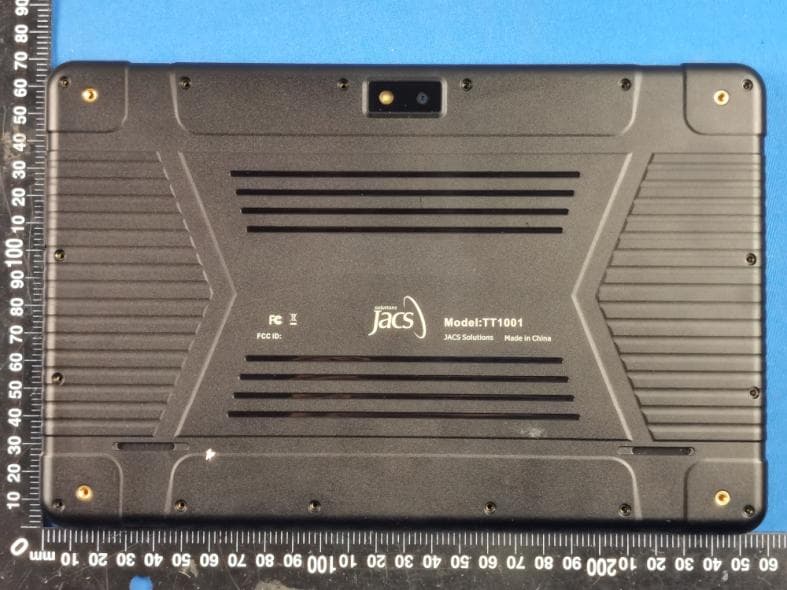
2AGCDJACSTT1001V1
Jun 30, 2021TT1001 10.1 inch Tablet
Equipment Class
NII - Unlicensed National Information Infrastructure TX