2AGGZ003B9ACA45Solar Powered Wind and Light Sensor
Rollease Acmeda Inc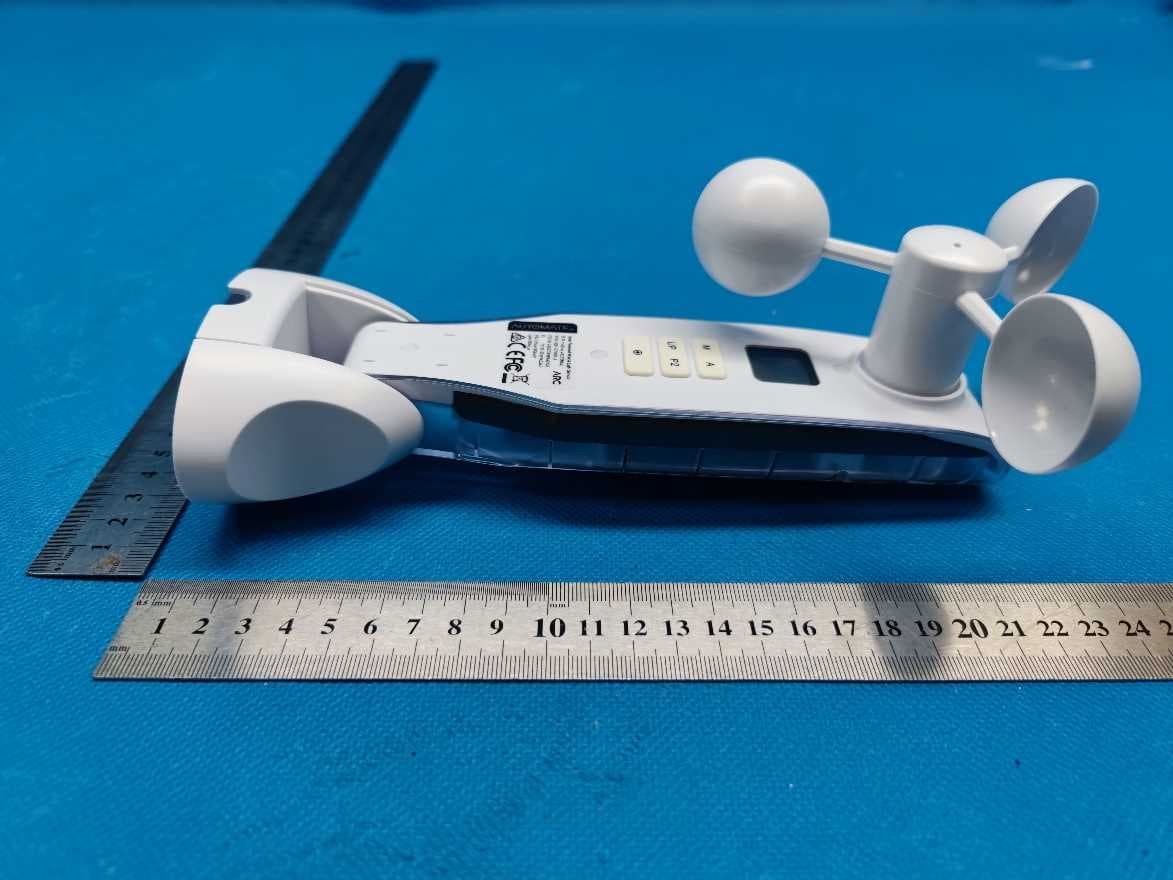
Click to zoom
Application Details
- Equipment Class
- DSC - Part 15 Security/Remote Control Transmitter
- Date of Grant
- Jan 29, 2023
- Application Purpose
- Original Equipment
- Date of Application
- Jan 15, 2023
- Equipment Note
- Solar Powered Wind and Light Sensor
- Frequency Range
- 433.92000000 - 433.92000000
- Company
- Rollease Acmeda Inc
- Country
- United States
Documents & Files
Document Text
Text extracted from the exhibit documents filed with the FCC. Open a document above to read the original.
Users Manual
FEATURES: • Measure wind speed with an anemometer • Measure light intensity with a Lux meter • LCD display • ARC compatibility • USB-C Charging Port • Solar Charging Panel • Loss of communication Safeguard Technology AUTOMATE™ | Wind-Light sensor is a device for measuring wind speed and light intensity. The information is transmitted to ARC outdoor motorized shades that will move to their top or bottom limits. SOLAR POWERED WIND & LIGHT SENSOR MT02-0301-072001_PRGM_v2.3_MAR 2022 2 | Automate ™ Programming Instructions | MT02-0301-072001 ROLLEASE ACMEDA 1 STATIC TITLESAFETY INSTRUCTIONS WARNING: Important safety instructions to be read before installation and use. Incorrect installation or use can lead to serious injury and will void manufacturer’s liability and warranty. It is important for the safety of persons to follow the enclosed instructions. Save these instructions for future reference. Statement Regarding FCC Compliance This device complies with Part 15 of the FCC Rules / Innovation, Science and Economic Development Canada’s licence-exempt RSS(s). Operation is subject to the following two conditions: (1) This device may not cause harmful interference, and (2) This device must accept any interference received, including interference that may cause undesired operation. L’émetteur/récepteur exempt de licence contenu dans le présent appareil est conforme aux CNR d’Innovation, Sciences et Développement économique Canada applicables aux appareils radio exempts de licence. L’exploitation est autorisée aux deux conditions suivantes : 1. L’appareil ne doit pas produire de brouillage; 2. L’appareil doit accepter tout brouillage radioélectrique subi, même si le brouillage est susceptible d’en compromettre le fonctionnement. Changes or modifications not expressly approved by the party responsible for compliance could void the user’s authority to operate the equipment. Note: This equipment has been tested and found to comply with the limits for a Class B digital device, pursuant to Part 15 of the FCC Rules. These limits are designed to provide reasonable protection against harmful interference in a residential installation. This equipment generates, uses and can radiate radio frequency energy and, if not installed and used in accordance with the instructions, may cause harmful interference to radio communications. However, there is no guarantee that interference will not occur in a particular installation. If this equipment does cause harmful interference to radio or television reception, which can be determined by turning the equipment off and on, the user is encouraged to try to correct the interference by one or more of the following measures: Do not dispose of in general waste. Please recycle batteries and damaged electrical products appropriately. • Do not submerge in water or expose to extreme temperatures. • Persons (including children) with reduced physical, sensory or mental capabilities, or lack of experience and knowledge should not be allowed to use this product. • Use or modification outside the scope of this instruction manual will void warranty. • Installation and programming to be performed by a suitably qualified installer. • Follow installation instructions. • For use with motorized shading devices. • Keep away from children. • Frequently inspect for improper operation. Do not use if repair or adjustment is necessary. • Keep clear when in operation. • Replace battery with correctly specified type. Rollease Acmeda declares this equipment is in compliance with the essential requirements and other relevant provisions of R&TTE Directive 2014/53/EU • Reorient or relocate the receiving antenna. • Increase the separation between the equipment and receiver. • Connect the equipment into an outlet on a circuit different from that to which the receiver is connected. • Consult the dealer or an experienced radio/TV technician for help. ROLLEASE ACMEDA Automate ™ Programming Instructions | MT02-0301-072001 | 3 1 STATIC TITLECONTENTS 1 INSTALLATION 4 2 OVERVIEW 5 2.1 Components 5 2.2 LCD Display 6 2.3 Safeguard Technology 6 3 SETUP 7 3.1 Pair the motor to a remote (if required) 7 3.2 Check motor Direction 7 3.3 Pair or Unapir the Sensor to a Motor using a Pre-Paired Remote 8 3.4 Setup wind speed control 8 3.5 Setup light control 9 4 ADDITIONAL FUNCTIONS 10 4.1 Display measured wind speed & light intensity 10 4.2 Display the pre-set threshold value 10 4.3 Wind Sensor Function 11 4.4 Light Sensor Function 11 4.5 Activate/Deactivate Sun & Wind sensor functionality on the motor 12 5 TROUBLESHOOTING 13 6 NOTES 14 4 | Automate ™ Programming Instructions | MT02-0301-072001 ROLLEASE ACMEDA 1. Find an appropriate location with direct sunlight and in a location that will see the same wind conditions the paired device will see. 2. Remove the base covers 3. The solar panel must be face up and in direct sunlight 4. Fix the sensor to a suitable surface 5. Re-attach the base covers 6. Ensure the three rotating cups are in an approximately horizontal position 1 INSTALLATION Transmission Distance: 35 meters indoors 200 meters open space ROLLEASE ACMEDA Automate ™ Programming Instructions | MT02-0301-072001 | 5 2.1 COMPONENTS Luminosity Sensor Solar Panel Anemometer cup Display Menu Up Adjust P2 Factory Reset Button 2 OVERVIEW USB-C Charging Port 6 | Automate ™ Programming Instructions | MT02-0301-072001 ROLLEASE ACMEDA 1. The LCD screen lighting stays active for 30 seconds. If there is no operation, the sensor automatically switches its screen off for energy saving, but the program will keep running for normal detection and command transmissions. When the screen is off, pressing any (non-reset) button triggers the screen to be on again for another minute. 2. Sun icon: indicates the light intensity detection mode. 3. Flag icon: indicates the wind speed detection mode. 4. Battery icon: The voltage of the internal battery is checked by its inner program once every day. The appearance of this battery icon indi…
Text truncated - open the document above for the full version.
Cover Letter(s)
1 of 1 To whom it may concern, Date: 2022/11/10 To: Federal Communications Commission 7435 Oakland Mills Road Columbia MD FCC ID: 2AGGZ003B9ACA45 To Whom It May Concern: This letter is to ascertain that Rollease Acmeda Inc, Product name: Solar Powered Wind & Light Sensor , Model: MT02‐0301‐072001‐A has been the units used for conducting FCC compliance testing, the SDoC part will be tested by FCC recognized test lab. If you have any questions or concerns, please contact us. Yours sincerely, Company name: Rollease Acmeda Inc Address: 750 East Main Street, 7th Floor, Stamford CT 06902, USA E‐mail: [email protected] Tel: + 1 203 832 6756 Signature:
External Photos
External Photos Documentation Manufacturer: Rollease Acmeda Inc Page 1 of 3 Product: Solar Powered Wind & Light Sensor FCC ID: 2AGGZ003B9ACA45 IC: 21769-003B9ACA45 Model: MT02-0301-072001-A External Photos Documentation Manufacturer: Rollease Acmeda Inc Page 2 of 3 Product: Solar Powered Wind & Light Sensor FCC ID: 2AGGZ003B9ACA45 IC: 21769-003B9ACA45 External Photos Documentation Manufacturer: Rollease Acmeda Inc Page 3 of 3 Product: Solar Powered Wind & Light Sensor FCC ID: 2AGGZ003B9ACA45 IC: 21769-003B9ACA45
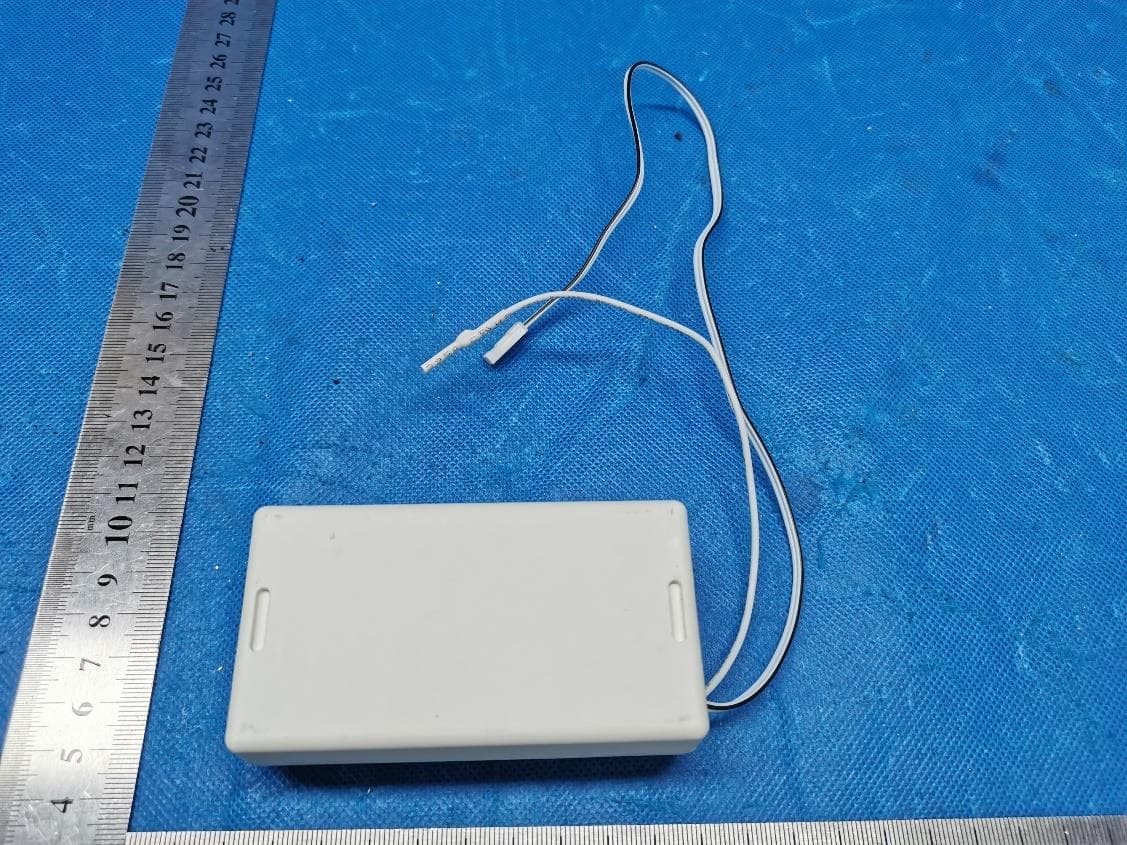
Internal Photos
Internal Photos Documentation Manufacturer: Rollease Acmeda Inc Page 1 of 3 Product: Solar Powered Wind & Light Sensor FCC ID: 2AGGZ003B9ACA45 IC: 21769-003B9ACA45 Model: MT02-0301-072001-A Internal Photos Documentation Manufacturer: Rollease Acmeda Inc Page 2 of 3 Product: Solar Powered Wind & Light Sensor FCC ID: 2AGGZ003B9ACA45 IC: 21769-003B9ACA45 Internal Photos Documentation Manufacturer: Rollease Acmeda Inc Page 3 of 3 Product: Solar Powered Wind & Light Sensor FCC ID: 2AGGZ003B9ACA45 IC: 21769-003B9ACA45 Antenna location
RF Exposure Info
Report No: 709502211931-00B EMC_SHA_F_R_02.06E TÜV SÜD Certification and Testing (China) Co., Ltd. Shanghai Branch 3-13, No.151, Heng Tong Road, Shanghai, 200070, P.R. China Phone: +86 21 61410123, Fax:+86 21 61408600 Page 1 of 4 Rev. 171.00 RF Exposure Estimation 1.Introduction Applicant:Rollease Acmeda Inc Address:7th Floor / 750 East Main Street, Stamford, CT 06902, USA Product:Solar Powered Wind & Light Sensor FCC ID:2AGGZ003B9ACA45 IC:21769-003B9ACA45 Model No.:MT02-0301-072001-A Reference RF report # 709502211931-00A 2.B.2 Blanket 1 mW Blanket Exemption The 1 mW Blanket Exemption of § 1.1307(b)(3)(i)(A) applies for single fixed, mobile, and portable RF sources with available maximum time-averaged power of no more than 1 mW, regardless of separation distance. The 1 mW blanket exemption applies at separation distances less than 0.5 cm, including where there is no separation. This exemption shall not be used in conjunction with other exemption criteria other than those for multiple RF sources in paragraph § 1.1307(b)(3)(ii)(A). The 1 mW exemption is independent of service type and covers the full range of 100 kHz to 100 GHz, but it shall not be used in conjunction with other exemption criteria or in devices with higher-power transmitters operating in the same time-averaging period. Exposure from such higher-power transmitters would invalidate the underlying assumption that exposure from the lower-power transmitter is the only contributor to SAR in the relevant volume of tissue. 3.RF Exposure Evaluation Per the test report included herein, for 433.92MHz According to C63.10 Annex G EIRP = pt × gt =( E × d)2 /30, so pt=( E × d)2 /30* gt where pt is the transmitter output power in watts gt is the numeric gain of the transmitting antenna (dimensionless) E is the electric field strength in V/m d is the measurement distance in meters (m) transmitter output power for 433.92MHz Function Field strength (E):89.77 (dBuV/m) = 0.0308 (V/m) Measurement distance (D):3 (m) Antenna Gain, typical (dBi):0.5 Numerical gain of the transmit antenna (gt):1.12 Transmitter output power (TP):0.000254(W) Transmitter output power (TP):0.254(mW) Report No: 709502211931-00B EMC_SHA_F_R_02.06E TÜV SÜD Certification and Testing (China) Co., Ltd. Shanghai Branch 3-13, No.151, Heng Tong Road, Shanghai, 200070, P.R. China Phone: +86 21 61410123, Fax:+86 21 61408600 Page 2 of 4 Rev. 171.00 We used the maximum ERP/EIRP to perform RF exposure exemption evaluation. Evaluation methodExempt Limit (mW)Verdict n Blanket 1 mW Blanket Exemption1mWYes o MPE-based Exemption(ERP)7mW(ERP)N/A o SAR-based Exemption (Pth)3060mWN/A So, the device is qualified for SAR test exemption, the exemption report is in lieu of the SAR report. Report No: 709502211931-00B EMC_SHA_F_R_02.06E TÜV SÜD Certification and Testing (China) Co., Ltd. Shanghai Branch 3-13, No.151, Heng Tong Road, Shanghai, 200070, P.R. China Phone: +86 21 61410123, Fax:+86 21 61408600 Page 3 of 4 Rev. 171.00 Innovation, Science and Economic Development Canada (ISED) MPE / Health Hazard Requirement for the 433.92MHz According to Innovation, Science and Economic Development Canada (ISED) RSS-102 Issue 5, Section 2.5.1, SAR evaluation is required if the separation distance between the user and/or bystander and the antenna and/or radiating element of the device is less than or equal to 20 cm, except when the device operates at or below the applicable output power level (adjusted for tune-up tolerance) for the specified separation distance defined in Table 1. RESULTS Per the test report included herein, for 433.92MHz According to RSS-GEN (6.12 Transmitter output power), If the antenna is not detachable, field strength measurements shall be made using a test site that complies with the appropriate normative reference. Report No: 709502211931-00B EMC_SHA_F_R_02.06E TÜV SÜD Certification and Testing (China) Co., Ltd. Shanghai Branch 3-13, No.151, Heng Tong Road, Shanghai, 200070, P.R. China Phone: +86 21 61410123, Fax:+86 21 61408600 Page 4 of 4 Rev. 171.00 Frequency (MHz) Max. Field Strength (dBuV/m)@3m Antenna Gain (dBi) Maximum Antenna Gain (numeric) Max. Output Power (mW) Min. test separation distance (mm) 433.9289.77 (Note 1) 0.51.120.254 (Note 3) 5mm Note: 1. Field Strength (dBuV/m@3m) test result please refer to test report 709502211931-00A. 2. Output power (dBm) = where D is the distance in metres between the measurement antenna and the transmit antenna (of the EUT) and G is the numerical gain of the transmit antenna, referenced to isotropic gain, in dBi. 3. Output power (mW) = 10^ (Max power (dBm)/10) EIRP (PK) = 0.254mW < 52 mW (At separation distance of ≤5 mm) - TÜV SÜD Certification and Testing (China) Co., Ltd. Shanghai Branch Reviewed by: Prepared by:Tested by: _____________________ ___________________________________________ Hui TONGWenqiang LUHuili CHENG EMCSectionManagerEMCProjectEngineerEMCTest Engineer Date: Dec. 02, 2022 Date: Dec. 02, 2022 Date: Dec. 02, 2022 -------------------------------------------------------End of Test Report--------------------------------------------------------------------
Test Report
Report Number: 709502211931-00A EMC_SHA_F_R_02.01E TÜV SÜD Certification and Testing (China) Co., Ltd. Shanghai Branch 3-13, No.151, Heng Tong Road, Shanghai, 200070, P.R. China Phone: +86 21 61410123, Fax:+86 21 61408600 Page 1 of 25 Rev. 171.00 FCC/IC – TEST REPORT Report Number:709502211931-00ADate of Issue: November 14, 2022 Model:MT02-0301-072001-A Product Type:Solar Powered Wind & Light Sensor Applicant:Rollease Acmeda Inc Address:7th Floor / 750 East Main Street, Stamford, CT 06902, USA Production Facility:Ningbo Dooya Mechanic & Electronic Technology Co.,Ltd Address:No.168 Shengguang Road,Luotuo,Zhenhai, 315202 Ningbo,Zhejiang province, :People'sRepublic of China Test Result:nPositiveoNegative Total pages including Appendices: 25 TÜV SÜD Certification and Testing (China) Co., Ltd. Shanghai Branch is a subcontractor to TÜV SÜD Product Service GmbH according to the principles outlined in ISO 17025. TÜV SÜD Certification and Testing (China) Co., Ltd. Shanghai Branch reports apply only to the specific samples tested under stated test conditions. Construction of the actual test samples has been documented. It is the manufacturer's responsibility to assure that additional production units of this model are manufactured with identical electrical and mechanical components. The manufacturer/importer is responsible to the Competent Authorities in Europe for any modifications made to the production units which result in non-compliance to the relevant regulations. TÜV SÜD Certification and Testing (China) Co., Ltd. Shanghai Branch shall have no liability for any deductions, inferences or generalizations drawn by the client or others from TÜV SÜD Certification and Testing (China) Co., Ltd. Shanghai Branch issued reports. This report is the confidential property of the client. As a mutual protection to our clients, the public and ourselves, extracts from the test report shall not be reproduced except in full without our written approval. dc Report Number: 709502211931-00A EMC_SHA_F_R_02.01E TÜV SÜD Certification and Testing (China) Co., Ltd. Shanghai Branch 3-13, No.151, Heng Tong Road, Shanghai, 200070, P.R. China Phone: +86 21 61410123, Fax:+86 21 61408600 Page 2 of 25 Rev. 171.00 1 Table of Contents 1 Table of Contents .............................................................................................................................. 2 2 Details about the Test Laboratory ..................................................................................................... 3 3 Description of the Equipment Under Test .......................................................................................... 4 4 Summary of Test Standards.............................................................................................................. 5 5 Summary of Test Results .................................................................................................................. 6 6 General Remarks .............................................................................................................................. 7 7 Systems test configuration ................................................................................................................ 8 8 Test Setups ....................................................................................................................................... 9 9 Test Methodology ........................................................................................................................... 10 9.1 Conducted Emission ................................................................................................................ 10 9.2 Radiated Emission ................................................................................................................... 15 9.3 Bandwidth Measurement & 99% Occupied Bandwidth ............................................................. 19 9.4 Deactivation Time .................................................................................................................... 21 10 Test Equipment List ........................................................................................................................ 22 11 System Measurement Uncertainty ............................................................................................... 23 12 Photographs of Test Set-ups ....................................................................................................... 24 13 Photographs of EUT .................................................................................................................... 25 Report Number: 709502211931-00A EMC_SHA_F_R_02.01E TÜV SÜD Certification and Testing (China) Co., Ltd. Shanghai Branch 3-13, No.151, Heng Tong Road, Shanghai, 200070, P.R. China Phone: +86 21 61410123, Fax:+86 21 61408600 Page 3 of 25 Rev. 171.00 2 Details about the Test Laboratory Details about the Test Laboratory Test Site 1 Company name: TÜV SÜD Certification and Testing (China) Co., Ltd. Shanghai Branch No.16 Lane, 1951 Du Hui Road, Shanghai 201108, P.R. China FCC Registration Number: 820234 Designation Number: CN1183 IC Company Number: 25988 CAB identifier:CN0101 Telephone:+86 21 6141 0123 Fax:+86 21 6140 8600 Report Number: 709502211931-00A EMC_SHA_F_R_02.01E TÜV SÜD Certification and Testing (China) Co., Ltd. Shanghai Branch 3-13, No.151, Heng Tong Road, Shanghai, 200070, P.R. China Phone: +86 21 61410123, Fax:+86 21 61408600 Page 4 of 25 Rev. 171.00 3 Description of the Equipment Under Test Product:Solar Powered Wind & Light Sensor Model no./HVIN:MT02-0301-072001-A FCC ID:2AGGZ003B9ACA45 IC:21769-003B9ACA45 Rating:3.7VDCRechargeable battery, 5V DC USB charge input RF Transmission Frequency: 433.92MHz Modulation:FSK Antenna Type:PCB antenna Antenna Gain:0.5 dBi max (Declared by manufacturer) Description of the EUT:The Equipment Under Test (EUT) is a transceiver operated at 433.92MHz. Test sample no.:SHA-665325-11 Report Number: 709502211931-…
Text truncated - open the document above for the full version.
Test Setup Photos
Manufacturer: Rollease Acmeda Inc Product: Solar Powered Wind & Light Sensor FCC ID: 2AGGZ003B9ACA45 IC: 21769-003B9ACA45 2023 Not to be reproduced, except in its entirety,Page 1 of 2 without the Permission of TÜV SÜD Certification and Testing (China) Co., Ltd. Shanghai Branch PHOTOGRAPHS OF TEST SET UP Field Strength and Harmonics Test Setup Radiated Emission Setup 30MHz ~ 1GHz Above 1GHz Manufacturer: Rollease Acmeda Inc Product: Solar Powered Wind & Light Sensor FCC ID: 2AGGZ003B9ACA45 IC: 21769-003B9ACA45 2023 Not to be reproduced, except in its entirety,Page 2 of 2 without the Permission of TÜV SÜD Certification and Testing (China) Co., Ltd. Shanghai Branch Conducted Emission Test Setup
Contact Information
Applicant
Jonny Emilio Matuichuk(Product Manager - Motorization)
Test Firm
TUV SUD Certification and Testing (China) Co., LtdYi Ba
[email protected]86 21 6140 0132
Technical Specifications
| # | Rule Parts | Frequency Range | Power Output |
|---|---|---|---|
| 1 | 15.231 | 433.92 MHz - 433.92 MHz | - |
Other Applications from Rollease Acmeda Inc
2AGGZ003B9ACA49
Jul 27, 2023VT Tilt Motor
Equipment Class
DSR - Part 15 Remote Control/Security Device Transceiver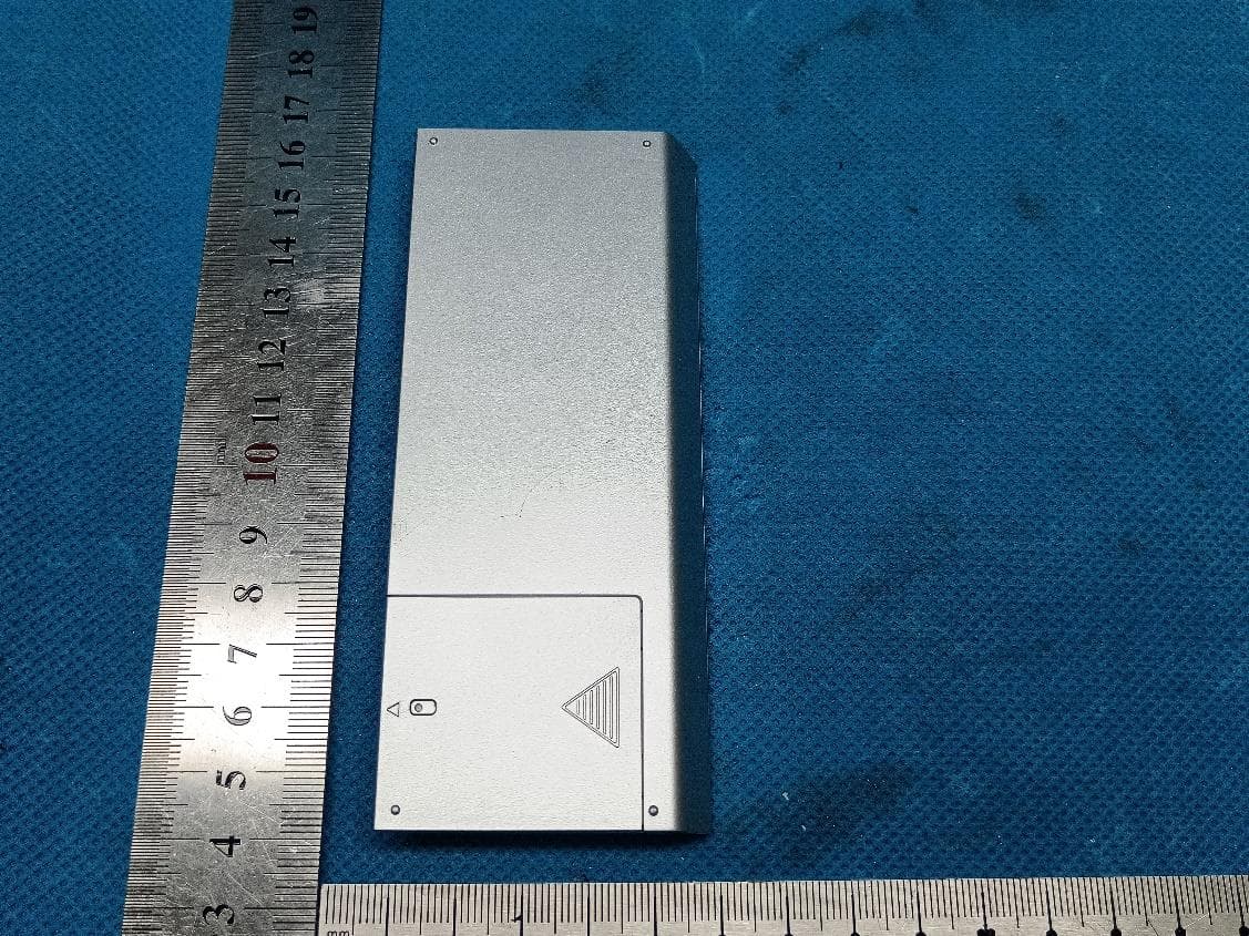
2AGGZ003B9ACA50
Jul 26, 2023Transmitter(Push one channel remote)
Equipment Class
DSC - Part 15 Security/Remote Control Transmitter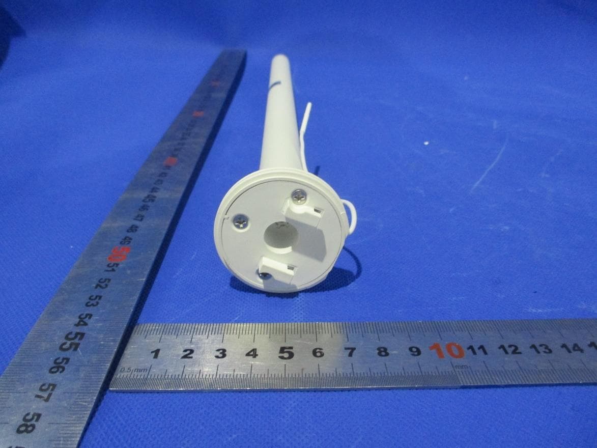
2AGGZ003B9ACA51
Jul 22, 2023Li-ion 0.5Nm ARC Motor
Equipment Class
DSR - Part 15 Remote Control/Security Device Transceiver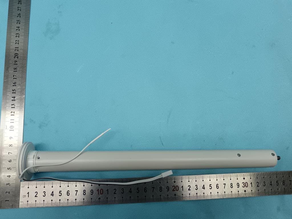
2AGGZ003B9ACA4C
Jul 08, 2023DC 1.1Nm ARC Motor
Equipment Class
DSR - Part 15 Remote Control/Security Device Transceiver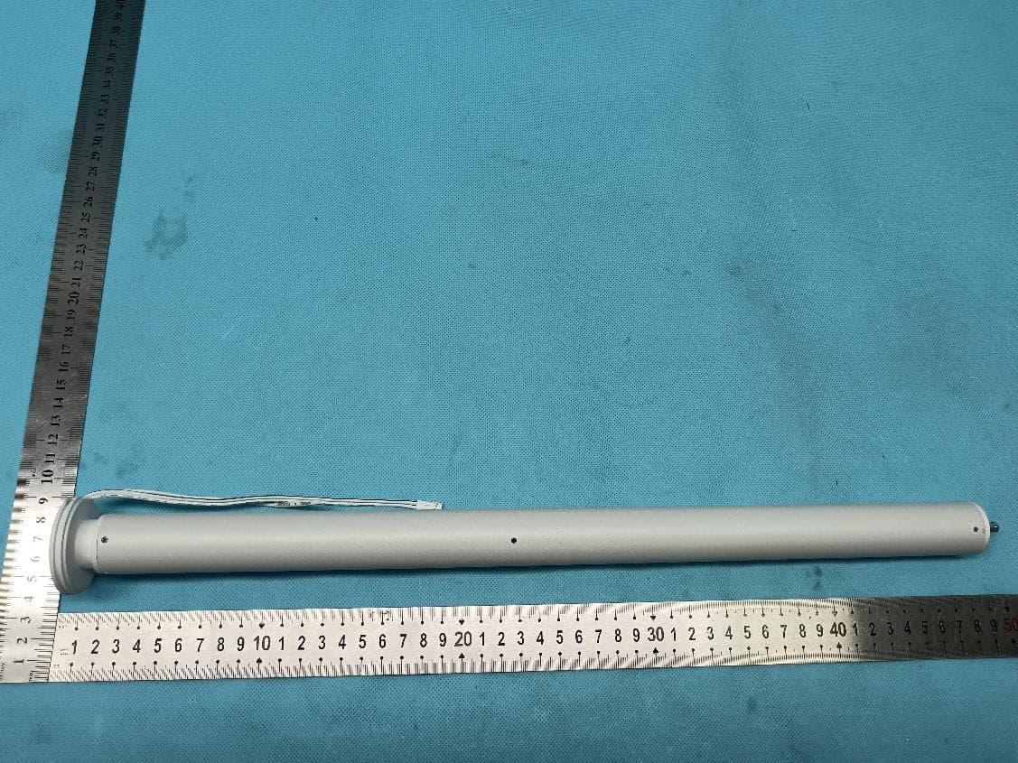
2AGGZ003B9ACA4D
Jul 08, 2023DC 2.0Nm ARC Motor
Equipment Class
DSR - Part 15 Remote Control/Security Device Transceiver