2AGGZMT013101001AUTOMATE DC 0.6Nm CL ARC Motor Ext. P1
Rollease Acmeda Inc
Click to zoom
Application Details
- Equipment Class
- DSR - Part 15 Remote Control/Security Device Transceiver
- Date of Grant
- May 13, 2020
- Application Purpose
- Original Equipment
- Date of Application
- May 13, 2020
- Equipment Note
- AUTOMATE DC 0.6Nm CL ARC Motor Ext. P1
- Frequency Range
- 433.92500000 - 433.92500000
- Company
- Rollease Acmeda Inc
- Country
- United States
Documents & Files
Document Text
Text extracted from the exhibit documents filed with the FCC. Open a document above to read the original.
Users Manual
AUTOMATE ™ ARC ™ CORD LIFT MOTORS 433 MHZ BI-DIRECTIONAL ELECTRONIC LIMIT SELECTABLE RPM FAVORITE POSITION LEVEL CONTROL FEATURES: • Smart Home Control • IOT Integration • Electronic Limits • 433 MHz Bi-Directional RF Communication • Leveling Control • 3 x Selectable Rpm • Favorite Position • Roller & Tilt Modes. AUTOMATE ™ | ARC ™ Cord Lift motors enable motorized function of shades utilizing cord take up systems. The Leveling Control allows for precise positioning of individual or multiple shades ensuring perfect alignment every time. Additionally, a favorite position can be pre-set and recalled at any time. MT01-3101-069001_PRGM_GL_v1.0_ NOV2019 Part numberDescription MT01-3101-069001Cord Lift DCRF Motor with extended P1 Button - 0.6N/34 2 | Automate™ Programming Instructions | Cord Lift Motor with Extended P1 Button Cable ROLLEASE ACMEDA CONTENTS 1 P1 BUTTON FUNCTIONS 4 1.1 Motor State Test 4 1.2 Motor Configuration Options 4 2 INITIAL SET-UP 5 2.1 Pair Motor with controller 5 2.2 Check motor direction 5 2.3 Set limits 6 3 ADJUSTING LIMITS 7 3.1 Adjust upper limit 7 3.2 Adjust lower limit 7 4 ADDING OR REMOVING CONTROLLERS AND CHANNELS 8 4.1 Using motor P1 button 8 4.2 Using a pre-existing controller 8 5 FAVORITE POSITIONING 9 5.1 Set favorite position 9 5.2 Send shade to favorite position 9 5.3 Delete favorite position 9 6 ADJUSTING MOTOR SPEED 10 6.1 Increase or decrease motor speed 10 7 TILT & ROLLER MODE 11 7.1 Enter tilt mode 11 7.2 Enter roller mode (Default) 11 8 SLEEP MODE 12 8.1 Enter sleep mode 12 8.2 Exit sleep mode 12 9 SOFT STOP ON/OFF 13 9.1 SOFT STOP ON 13 9.2 SOFT STOP OFF 13 10 BATTERY CHECK FUNCTION 14 10.1 Send Shade to battery charge level 14 11 TROUBLESHOOTING 15 3 | Automate™ Programming Instructions | Cord Lift Motor with Extended P1 Button Cable ROLLEASE ACMEDA SAFETY INSTRUCTIONS WARNING: Important safety instructions to be read before installation. Incorrect installation can lead to serious injury and will void manufacturer’s liability and warranty. CAUTION • Do not expose to moisture or extreme temperatures. • Do not allow children to play with this device. • Use or modification outside the scope of this instruction manual will void warranty. • Installation and programming to be performed by a suitably qualified installer. • For use within tubular blinds. • Ensure correct crown and drive adaptors are used for the intended system. • Keep antenna straight and clear from metal objects • Do not cut the antenna. • Use only Rollease Acmeda hardware. • Before installation, remove any unnecessary cords and disable any equipment not needed for powered operation. • Ensure torque and operating time is compatible with end application. • Do not expose the motor to water or install in humid or damp environments. • Motor is to be installed in horizontal application only. • Do not drill into motor body. • The routing of cable through walls shall be protected by isolating bushes or grommets. • Ensure power cable and aerial is clear and protected from moving parts. • If cable or power connector is damaged do not use. Important safety instructions to be read prior to operation. • It is important for the safety of persons to follow the enclosed instructions. Save these instructions for future reference. • Persons (including children) with reduced physical, sensory or mental capabilities, or lack of experience and knowledge should not be allowed to use this product. • Keep remote controls away from children. • Frequently inspect for improper operation. Do not use if repair or adjustment is necessary. • Keep motor away from acid and alkali. • Do not force the motor drive. • Keep clear when in operation. Do not dispose of in general waste. Please recycle batteries and damaged electrical products appropriately. 5005833 4 | Automate™ Programming Instructions | Cord Lift Motor with Extended P1 Button Cable ROLLEASE ACMEDA 1.1 Motor State Test 1 P1 BUTTON FUNCTIONS Activate P1 To execute the “P1 function” •Short circuit the white and dotted white wire •The motor will jog once •Release the wires Now you are able to pair the motor with the remote.” Activate Pairing Mode Motor Response Approx. Approx. P1 Press ConditionFunction Achieved Visual Feedback Audible Feedback Function Described Short Press then Release (<2 sec) If limit is NOT setNoneNo ActionNoneNo Action If limits are set Operational control of motor, run to limit. Stop if running Motor runsNone Operational control of motor after pairing and limit setting is completed first time If motor is in “Sleep Mode” & limits are set (Refer to Sec.10) Wake and control Motor wakes and runs in a direction None Motor is restored from Sleep mode and RF control is active This table describes the function of a short P1 button press/release(<2 seconds) depending on current motor configuration. 1.2 Motor Configuration Options The P1 Button is utilized to administer motor configuration as described below and beginning in Section 4. Sleep Mode Approx. Motor Response Reverse Direction Motor Response Motor Response RELEASE P1 RELEASE P1 RELEASE P1 Settings Approx. Reset To Factory SECS 6 SECS 14 5 | Automate™ Programming Instructions | Cord Lift Motor with Extended P1 Button Cable ROLLEASE ACMEDA Select channel on controller. (Disregard if using single channel controller) Activate P1 buttonHold STOP on controller IMPORTANT Motor ResponseMotor Response Consult user manual for your controller for information on selecting channel. RELEASE P1 Motor is now in setup mode and ready for setting limits. 2 INITIAL SET-UP 2.1 Pair Motor with controller 2.2 Check motor direction To check travel direction of shade, press UP or DOWN on controller. To reverse shade direction, hold both UP and DOWN until motor responds Motor Reponse Reversing motor direction using this method is only possible during initial set-up, prior to first time limit setting, or after a re-set of motor 6 | Automate™ Programming Instructions | Cord Lift Motor with Extended P1 Button Cable R…
Text truncated - open the document above for the full version.
Cover Letter(s)
QA-FR-170-B Company: Rollease Acmeda Inc Add: 750 East Main Street, 7th Floor, Stamford, Connecticut 06902 United States Tel: 7202037285 Fax: (203) 964-1503 FCC Authorization Date: 2019-12-20 FE DERAL COMMUNICATIONS COMMISSION Authorization and Evaluation Division 7435 Oakland Mills Road Columbia, MD 21046 Subject: Agent Authorization To whom it may concern: We, Rollease Acmeda Inc, the undersigned, Hereby authorizes Bay Area Compliance Laboratories Corporation to act on its behalf in all matters relating to application for Equipment authorization, including the signing of all documents relating to these matters. All acts carried o ut by Bay Area Compliance Laboratories Corp. on our behalf shall have the same effect as our own action. We, the undersigned, hereby certify that we are not subject to a denial of federal benefits, that includes FCC benefits, pursuant to Section 5301 of the Anti-Drug Abuse Act of 1988, 21 U.S.C. 862. This authorization is valid until further written notice from the applicant. Sincerely Yours, Signature: Typed or Printed Name: Jere Gianola Title: Program Manager - Motorization
Cover Letter(s)
Co mpany: Rollease Acmeda Inc Add: 750 East Main Street, 7th Floor, Stamford, Connecticut 06902 United States Tel: 720203728 5 Fax: (203) 964-1503 E-mail: [email protected] FCC Confidential Authorization Date: 2019-12-20 FEDERAL COMMUNICATIONS COMMISSIONS Authorization and Evaluation Division 7435 Oakland Mills Road Columbia, MD 21046 Subject: Confidentiality Request regarding application for certification of FCC ID: 2AGGZMT013101001 To: whom it may concern, In accordance with Sections 0.457 and 0.459 of the Commission’s Rules, Rollease Acmeda Inc hereby requests long-term confidential treatment of information accompanying this application as outlined below: Block Diagram Schematics Operation Description The above materials contain proprietary and confidential information not customarily released to the public. The public disclosure of these materials provides unjustified benefits to its competitors in the market. Sincerely Yours, Signature: Typed or Printed Name: Jere Gianola Title: Program Manager - Motorization
External Photos
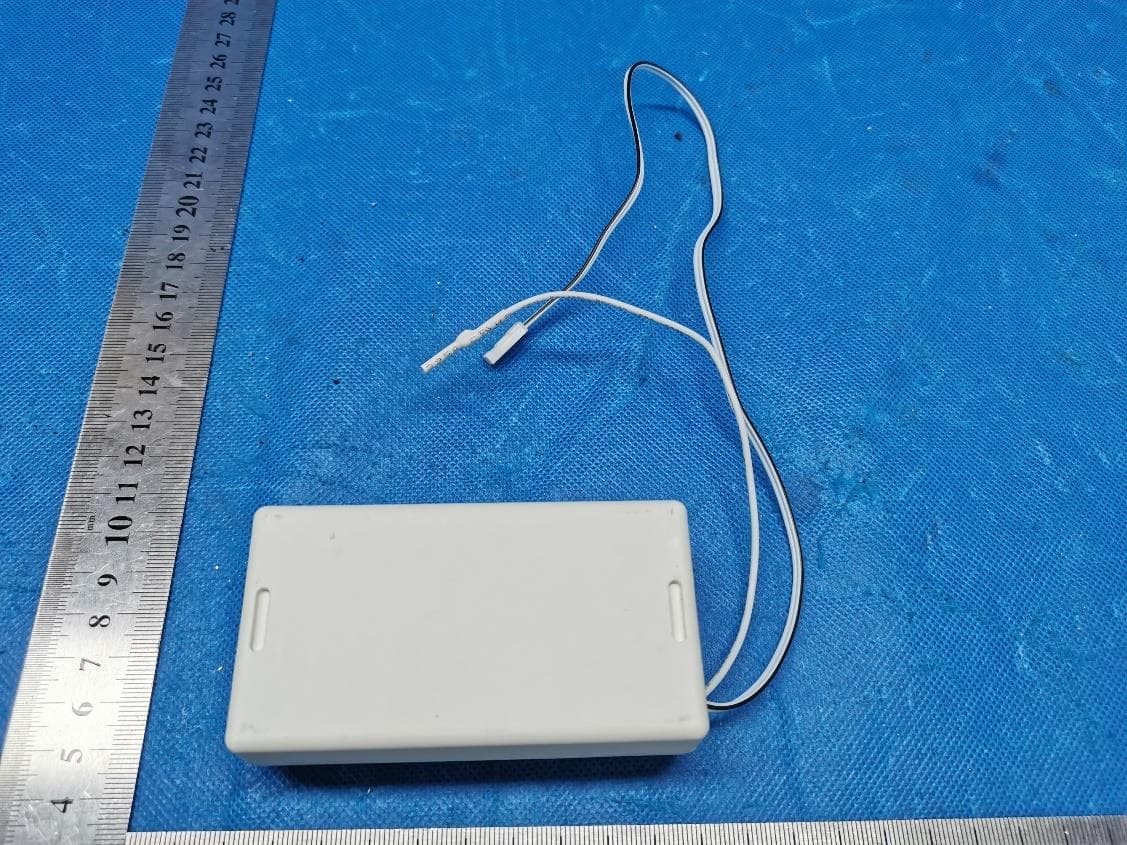
EXHIBIT A - EUT EXTERNAL PHOTOGRAPHS
Internal Photos
EXHIBIT B - EUT INTERNAL PHOTOGRAPHS Antenna
Test Report
Note: This test report is prepared for the customer shown above and for the device described herein. It may not be duplicated or used in part without prior written consent from Bay Area Compliance Laboratories Corp. This report is valid only with a valid digital signature. The digital signature may be available only under the Adobe software above version 7.0. FCC PART 15.231 TEST REPORT For Rollease Acmeda Inc 750 East Main Street, 7th Floor, Stamford, Connecticut 06902 United States FCC ID: 2AGGZMT013101001 Report Type: Original Report Product Type: AUTOMATE | DC 0.6Nm CL ARC Motor Ext. P1 Test Engineer: Winnie Yang Report Number: RSHA191220001-00B Report Date: 2020-04-30 Reviewed By: Oscar Ye EMC Manager Prepared By: Bay Area Compliance Laboratories Corp. (Kunshan) No.248 Chenghu Road, Kunshan, Jiangsu province, China Tel: +86-0512-86175000 Fax: +86-0512-88934268 www.baclcorp.com.cn Bay Area Compliance Laboratories Corp. (Kunshan) Report No.: RSHA191220001-00B FCC Part 15.231 Page 2 of 24 TABLE OF CONTENTS GENERAL INFORMATION ....................................................................................................................................... 3 PRODUCT DESCRIPTION FOR EQUIPMENT UNDER TEST (EUT) ..................................................................................... 3 OBJECTIVE ................................................................................................................................................................... 3 TEST METHODOLOGY .................................................................................................................................................. 3 MEASUREMENT UNCERTAINTY .................................................................................................................................... 4 TEST FACILITY ............................................................................................................................................................. 4 SYSTEM TEST CONFIGURATION .......................................................................................................................... 5 JUSTIFICATION ............................................................................................................................................................. 5 EUT EXERCISE SOFTWARE .......................................................................................................................................... 5 EQUIPMENT MODIFICATIONS ....................................................................................................................................... 5 SUPPORT EQUIPMENT LIST AND DETAILS .................................................................................................................... 5 EXTERNAL I/O CABLE .................................................................................................................................................. 5 BLOCK DIAGRAM OF TEST SETUP ................................................................................................................................ 6 SUMMARY OF TEST RESULTS ............................................................................................................................... 8 TEST EQUIPMENT LIST ........................................................................................................................................... 9 FCC§15.203 - ANTENNA REQUIREMENT ............................................................................................................ 10 APPLICABLE STANDARD ............................................................................................................................................ 10 ANTENNA CONNECTED CONSTRUCTION .................................................................................................................... 10 FCC §15.207 (A) - AC LINE CONDUCTED EMISSIONS ..................................................................................... 11 APPLICABLE STANDARD ............................................................................................................................................ 11 EUT SETUP ................................................................................................................................................................ 11 EMI TEST RECEIVER SETUP ....................................................................................................................................... 11 TEST PROCEDURE ...................................................................................................................................................... 11 FACTOR & OVER LIMIT CALCULATION ...................................................................................................................... 12 TEST RESULTS SUMMARY .......................................................................................................................................... 12 TEST DATA ................................................................................................................................................................ 12 FCC §15.205, §15.209, §15.231 (B) - RADIATED EMISSIONS ............................................................................. 15 APPLICABLE STANDARD ............................................................................................................................................ 15 EUT SETUP ................................................................................................................................................................ 16 EMI TEST RECEIVER SETUP ....................................................................................................................................... 17 TEST PROCEDURE .....................................................................................................................................................…
Text truncated - open the document above for the full version.
Test Setup Photos
EXHIBIT C - TEST SETUP PHOTOGRAPHS Conducted Emissions (Front View) Conducted Emissions (Side View) Radiated Emissions (Below 1GHz) Radiated Emissions (Above 1GHz)
Contact Information
Applicant
Jonny Emilio Matuichuk(Product Manager - Motorization)
Test Firm
Bay Area Compliance Laboratories Corp. (Kunshan)Mr. John Chan
[email protected]+86 0512 86175000
Technical Specifications
| # | Rule Parts | Frequency Range | Power Output |
|---|---|---|---|
| 1 | 15.231 | 433.925 MHz - 433.925 MHz | - |
Other Applications from Rollease Acmeda Inc
2AGGZ003B9ACA49
Jul 27, 2023VT Tilt Motor
Equipment Class
DSR - Part 15 Remote Control/Security Device Transceiver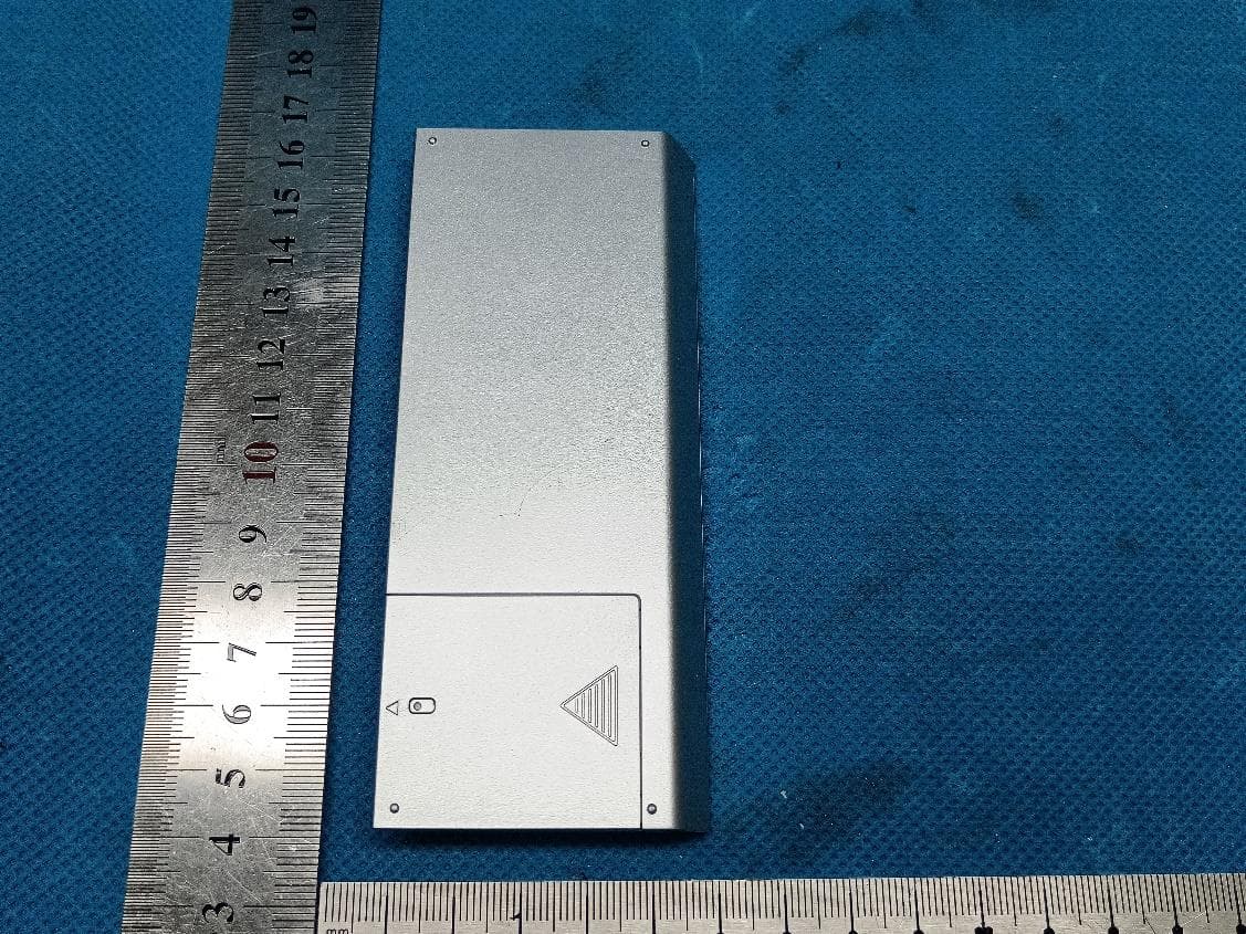
2AGGZ003B9ACA50
Jul 26, 2023Transmitter(Push one channel remote)
Equipment Class
DSC - Part 15 Security/Remote Control Transmitter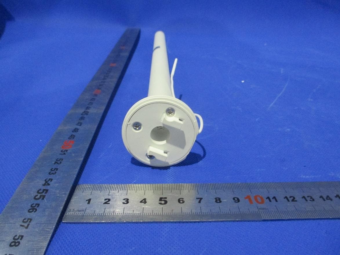
2AGGZ003B9ACA51
Jul 22, 2023Li-ion 0.5Nm ARC Motor
Equipment Class
DSR - Part 15 Remote Control/Security Device Transceiver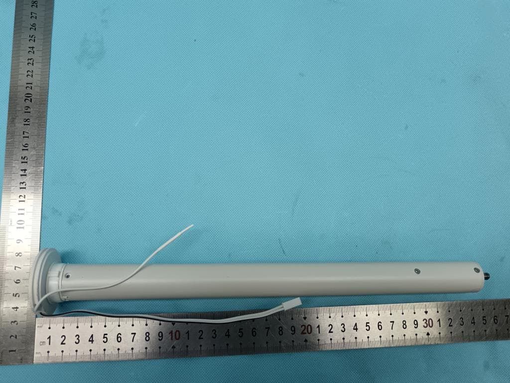
2AGGZ003B9ACA4C
Jul 08, 2023DC 1.1Nm ARC Motor
Equipment Class
DSR - Part 15 Remote Control/Security Device Transceiver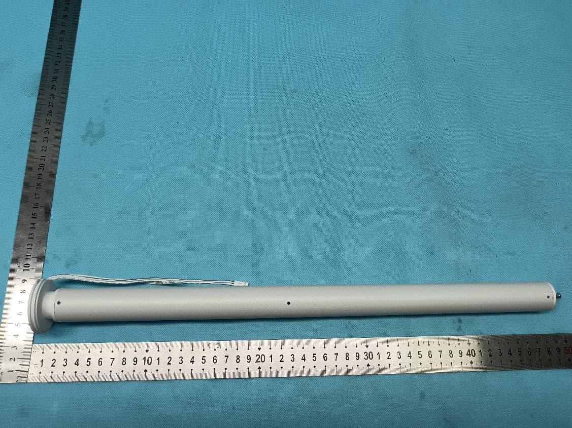
2AGGZ003B9ACA4D
Jul 08, 2023DC 2.0Nm ARC Motor
Equipment Class
DSR - Part 15 Remote Control/Security Device Transceiver