2AGGZMT014001001AUTOMATE Core Tilt Motor
Rollease Acmeda Inc
Click to zoom
Application Details
- Equipment Class
- DSR - Part 15 Remote Control/Security Device Transceiver
- Date of Grant
- May 14, 2020
- Application Purpose
- Original Equipment
- Date of Application
- May 14, 2020
- Equipment Note
- AUTOMATE Core Tilt Motor
- Frequency Range
- 433.92500000 - 433.92500000
- Company
- Rollease Acmeda Inc
- Country
- United States
Documents & Files
Document Text
Text extracted from the exhibit documents filed with the FCC. Open a document above to read the original.
Users Manual
1. Not operating under low voltage motors: When the power supply voltage is lower than 6.5 V, the motor stops running, and it can not start until the voltage exceeds 6.8V. When the power supply voltage is lower than 7.2V, the motor runs continuously and the buzzer will beep 10 times. When the power supply voltage is lower than 6.2V, the motor stops the buzzer beeping, and the voltage can be started only when the voltage is greater than 6.5V. 2. Operating The valid interval of the emitter button is 10s,the emitter will quit the set after 10s; The motor will run or beep for hint,please do the next step after the hint. 3. Set limit position After the up/down limit position setting,and the up/down limit position can’t at the same position; After limit setting,with power off and memory function; Into the match-code status 2 minutes later, it will quit out the setting limits status automatically; It will delete every memory and restore the factory settings. 4. When the motor running without any operation, the maximum running time is 6 minutes,it will stop automatically. 5. If the emitter lost,please setting up again with new emitter. Note: The left and right rotation of the hook controls the motor to reverse and the centering motor of the hook stops. Parameters(More m odels and parameters are subject to the nameplate) Note: it can be used with hook controller and battery rod, or only with battery or adapter. One motor maximum can store 10 channels,over 10 channels,if still need add new channels,it will be repeating covered in turn from second channel. Functional features: Switch Direction Built-in Receiver Jog & Tilt Preferred Stop Position Low Power Consumption, Suitable for External Battery Power Electronic Limit Stall Protection Program Button Solar Charging Reset to Factor Mode Unpair Single Emittert Operating temperature MT01-4001-069001 0.6N.m 10RPM 8.4V 0.54A 5W 433.925MHz Motor setting button(P1) Solar panel charging interface Adapter charging interface Hook Signal line The b attery bar Type Rated Torque(N.m) Rated Voltage(V) Rated Speed(RPM) Rated Current(A) Rated Power(W) Emission Frequency(MHz) P2 M P2 Lithium Cell 3V P2 Up button Stop button Down button Setting button & 0 45 FCC Warning: This equipment has been tested and found to comply with the limits for a Class B digital device, pursuant to part 15 of the FCC Rules. These limits are designed to provide reasonable protection against harmful interference in a residential installation. This equipment generates, uses and can radiate radio frequency energy and, if not installed and used in accordance with the instructions, may cause harmful interference to radio communications. However, there is no guarantee that interference will not occur in a particular installation. If this equipment does cause harmful interference to radio or television reception, which can be determined by turning the equipment off and on, the user is encouraged to try to correct the interference by one or more of the following measures: Reorient or relocate the receiving antenna. Increase the separation between the equipment and receiver. Connect the equipment into an outlet on a circuit different from that to which the receiver is connected. Consult the dealer or an experienced radio/TV technician for help. MODIFICATION: Any changes or modifications not expressly approved by the grantee of this device could void the user’s authority to operate the device. This device complies with part 15 of the FCC Rules. Operation is subject to the following two conditions: (1) This device may not cause harmful interference, and (2) This device must accept any interference received, including interference that may cause undesired operation. IC -English: This device complies with Industry Canada RSS standard(s). Operation is subject to the following two conditions: (1) this device may not cause interference, and (2) this device must accept any interference ,including interference that may cause undesired operation of the device. 2. Changes or modifications not expressly approved by the party responsible for compliance could void the user 's authority to operate the equipment. -French: Lepr ésent appareil est conforme aux CNR d'Industrie Canada applicable aux appareils radio Exempts de licence. L'exploitation est autorisée aux deux conditions suivantes : (1) l'appareil ne doit pas produire de brouillage, et (2) l 'utilisateur de l'appareil doit accepter tout brouillag e radioélectrique subi, meme si le brouillage est susceptible d'en compromettre le fonctionnement."l. AUTOMATE | Core Tilt Motor (Optional) (Optional) User manual AUTOMATE | Core Tilt Motor Run for hint x2 “Di” x3 Stop Run for hint x1“Di~” x1 T<10s loosen P1 Setting up is ok Press 2sPress 2s Press 1s Press 2s Press 5sPress 1s + Run for hint x1 The curtain run downward Successful change the direction 1, Set up limit 2, Set down limit UpUp+Stop DownStop+Down Note: If the limit setting is not completed, the limit setting mode is exited,if you already have a limit, you will continue to use the pre-set limit;After setting up the up and down limit into user mode,press the emitter up button or down button motor to run, release the button motor to stop running;When only one limit is set, the commutation operation is invalid. UpUp+Down P2StopStop Preferred stop posi- tion is ok Press 1sPress 1sPress 1s P2 1, Set preferred stop position After the up limit and down limit setting, you can set preferred stop position between them as the half open position. Note: If press the up button,the curtains run down,please perform a reversing operation; If not within 10s to be on the code emitter or no legal STOP button code, 10s limit to time, will automatically exit the setting up mode;After the success of the code will delete the original limit settings and motor running mode speed settings, restore the factory value. Note: After the success of the reversing,retain all motor original settings. Run for hint x1 “Di” x1 Run for hint …
Text truncated - open the document above for the full version.
Cover Letter(s)
QA-FR-170-B Company: Rollease Acmeda Inc Add: 750 East Main Street, 7th Floor, Stamford, Connecticut 06902 United States Tel: 7202037285 Fax: (203) 964-1503 FCC Authorization Date: 2019-12-23 FE DERAL COMMUNICATIONS COMMISSION Authorization and Evaluation Division 7435 Oakland Mills Road Columbia, MD 21046 Subject: Agent Authorization To whom it may concern: We, Rollease Acmeda Inc, the undersigned, Hereby authorizes Bay Area Compliance Laboratories Corporation to act on its behalf in all matters relating to application for Equipment authorization, including the signing of all documents relating to these matters. All acts carried o ut by Bay Area Compliance Laboratories Corp. on our behalf shall have the same effect as our own action. We, the undersigned, hereby certify that we are not subject to a denial of federal benefits, that includes FCC benefits, pursuant to Section 5301 of the Anti-Drug Abuse Act of 1988, 21 U.S.C. 862. This authorization is valid until further written notice from the applicant. Sincerely Yours, Signature: Typed or Printed Name: Jere Gianola Title: Program Manager - Motorization
Cover Letter(s)
Co mpany: Rollease Acmeda Inc Add: 750 East Main Street, 7th Floor, Stamford, Connecticut 06902 United States Tel: 720203728 5 Fax: (203) 964-1503 E-mail: [email protected] FCC Confidential Authorization Date: 2019-12-23 FEDERAL COMMUNICATIONS COMMISSIONS Authorization and Evaluation Division 7435 Oakland Mills Road Columbia, MD 21046 Subject: Confidentiality Request regarding application for certification of FCC ID: 2AGGZMT014001001 To: whom it may concern, In accordance with Sections 0.457 and 0.459 of the Commission’s Rules, Rollease Acmeda Inc hereby requests long-term confidential treatment of information accompanying this application as outlined below: Block Diagram Schematics Operation Description The above materials contain proprietary and confidential information not customarily released to the public. The public disclosure of these materials provides unjustified benefits to its competitors in the market. Sincerely Yours, Signature: Typed or Printed Name : Jere Gianola Title: Program Manager - Motorization
External Photos
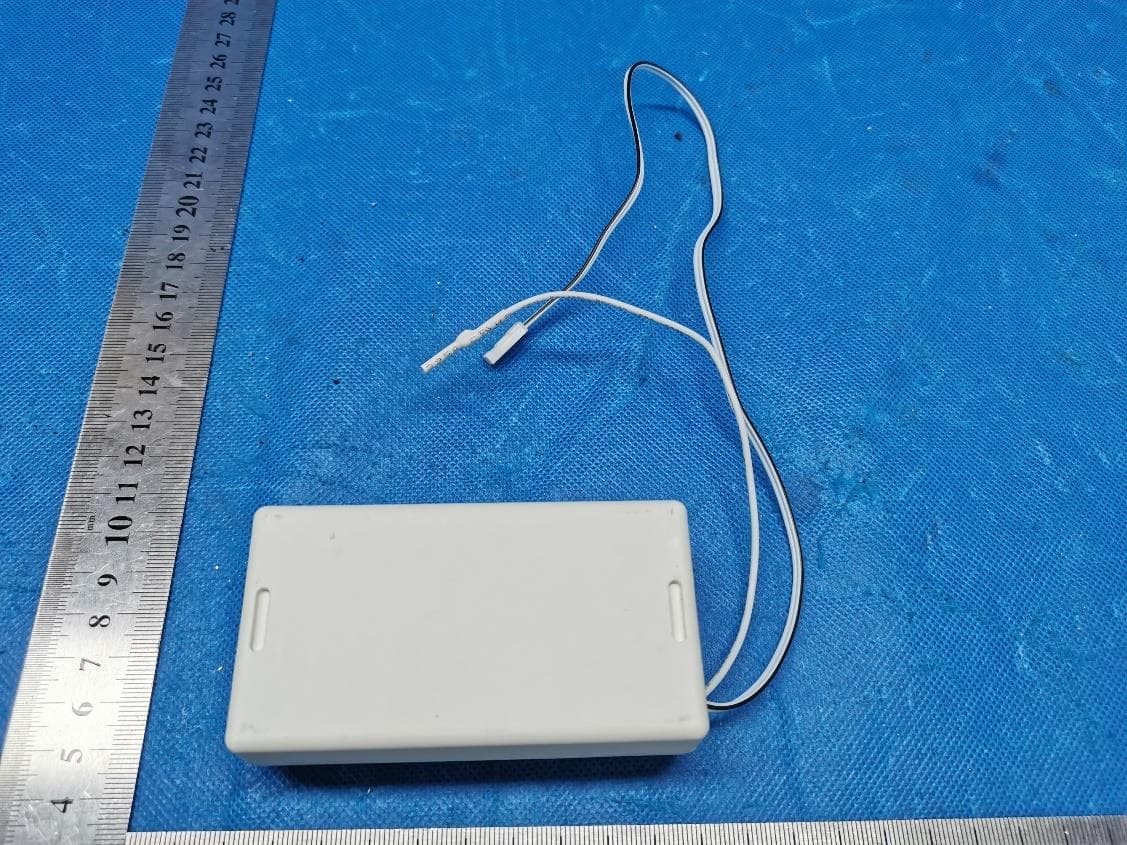
EXHIBIT A - EUT EXTERNAL PHOTOGRAPHS
ID Label/Location Info
MT01-4001-069001 [0.6Nm/10rpm] AUTOMATE | Core Tilt Motor Electric Limit - Venetian Blind DC Motor 0.54A 8.4V DC 433.925MHz 5W IP206min0.16kg MADE IN PRC FCC ID: 2AGGZMT014001001 IC:21769-MT014001001
Internal Photos
EXHIBIT B- EUT INTERNAL PHOTOGRAPHS Antenna
Test Report
Note: This test report is prepared for the customer shown above and for the device described herein. It may not be duplicated or used in part without prior written consent from Bay Area Compliance Laboratories Corp. This report is valid only with a valid digital signature. The digital signature may be available only under the Adobe software above version 7.0. FCC PART 15.231 TEST REPORT For Rollease Acmeda Inc 750 East Main Street, 7th Floor, Stamford, Connecticut 06902 United States FCC ID: 2AGGZMT014001001 Report Type: Original Report Product Type: AUTOMATE | Core Tilt Motor Test Engineer: Chao Gao Report Number: RSHA191223001-00B Report Date: 2020-05-07 Reviewed By: Oscar Ye EMC Manager Prepared By: Bay Area Compliance Laboratories Corp. (Kunshan) No.248 Chenghu Road, Kunshan, Jiangsu province, China Tel: +86-0512-86175000 Fax: +86-0512-88934268 www.baclcorp.com.cn Bay Area Compliance Laboratories Corp. (Kunshan) Report No.: RSHA191223001-00B FCC Part 15.231 Page 2 of 25 TABLE OF CONTENTS GENERAL INFORMATION ....................................................................................................................................... 3 PRODUCT DESCRIPTION FOR EQUIPMENT UNDER TEST (EUT) ..................................................................................... 3 OBJECTIVE ................................................................................................................................................................... 3 TEST METHODOLOGY .................................................................................................................................................. 3 MEASUREMENT UNCERTAINTY .................................................................................................................................... 4 TEST FACILITY ............................................................................................................................................................. 4 SYSTEM TEST CONFIGURATION .......................................................................................................................... 5 JUSTIFICATION ............................................................................................................................................................. 5 EUT EXERCISE SOFTWARE .......................................................................................................................................... 5 EQUIPMENT MODIFICATIONS ....................................................................................................................................... 5 SUPPORT EQUIPMENT LIST AND DETAILS .................................................................................................................... 5 EXTERNAL I/O CABLE .................................................................................................................................................. 5 BLOCK DIAGRAM OF TEST SETUP ................................................................................................................................ 6 SUMMARY OF TEST RESULTS ............................................................................................................................... 8 TEST EQUIPMENT LIST ........................................................................................................................................... 9 FCC§15.203 - ANTENNA REQUIREMENT ............................................................................................................ 10 APPLICABLE STANDARD ............................................................................................................................................ 10 ANTENNA CONNECTED CONSTRUCTION .................................................................................................................... 10 FCC §15.207 (A) - AC LINE CONDUCTED EMISSIONS ..................................................................................... 11 APPLICABLE STANDARD ............................................................................................................................................ 11 EUT SETUP ................................................................................................................................................................ 11 EMI TEST RECEIVER SETUP ....................................................................................................................................... 11 TEST PROCEDURE ...................................................................................................................................................... 11 FACTOR & OVER LIMIT CALCULATION ...................................................................................................................... 12 TEST RESULTS SUMMARY .......................................................................................................................................... 12 TEST DATA ................................................................................................................................................................ 12 FCC §15.205, §15.209, §15.231 (B) - RADIATED EMISSIONS ............................................................................. 15 APPLICABLE STANDARD ............................................................................................................................................ 15 EUT SETUP ................................................................................................................................................................ 16 EMI TEST RECEIVER SETUP ....................................................................................................................................... 17 TEST PROCEDURE ...................................................................................................................................................... 17 CORRECTED AM…
Text truncated - open the document above for the full version.
Test Setup Photos
EXHIBIT C- TEST SETUP PHOTOGRAPHS Conducted Emissions (Front View) Conducted Emissions (Side View) Radiated Emissions (Below 1GHz) Radiated Emissions (Above 1GHz)
Contact Information
Applicant
Jonny Emilio Matuichuk(Product Manager - Motorization)
Test Firm
Bay Area Compliance Laboratories Corp. (Kunshan)Mr. John Chan
[email protected]+86 0512 86175000
Technical Specifications
| # | Rule Parts | Frequency Range | Power Output |
|---|---|---|---|
| 1 | 15.231 | 433.925 MHz - 433.925 MHz | - |
Other Applications from Rollease Acmeda Inc
2AGGZ003B9ACA49
Jul 27, 2023VT Tilt Motor
Equipment Class
DSR - Part 15 Remote Control/Security Device Transceiver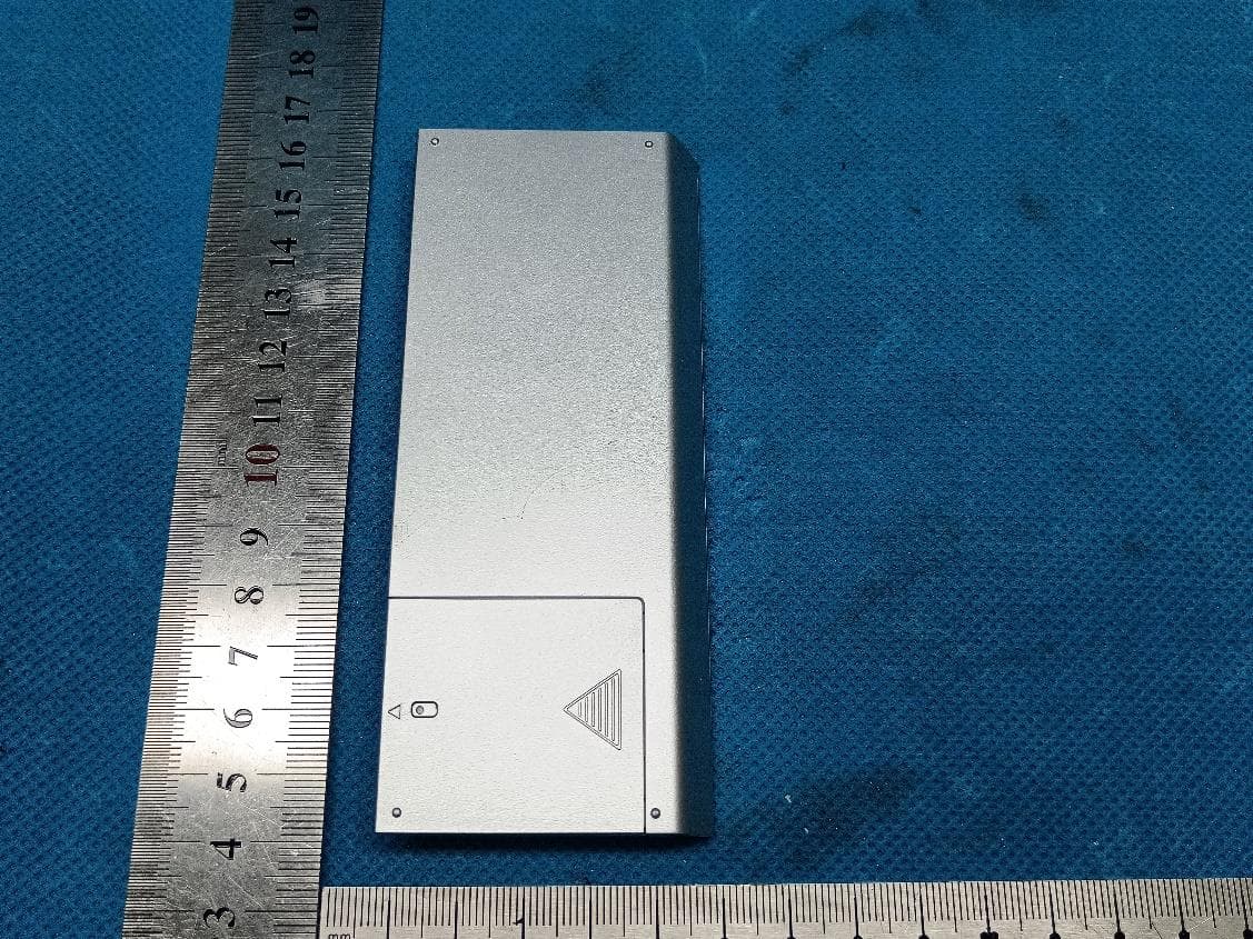
2AGGZ003B9ACA50
Jul 26, 2023Transmitter(Push one channel remote)
Equipment Class
DSC - Part 15 Security/Remote Control Transmitter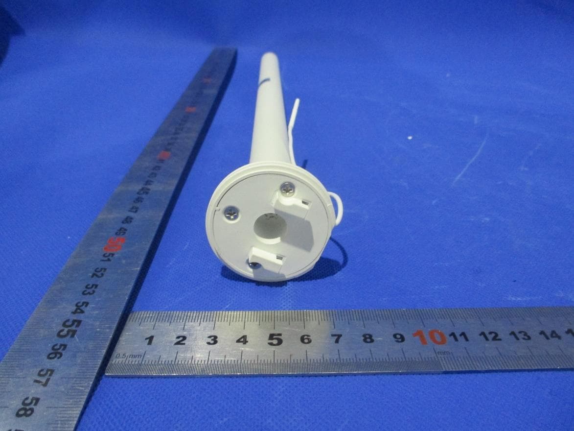
2AGGZ003B9ACA51
Jul 22, 2023Li-ion 0.5Nm ARC Motor
Equipment Class
DSR - Part 15 Remote Control/Security Device Transceiver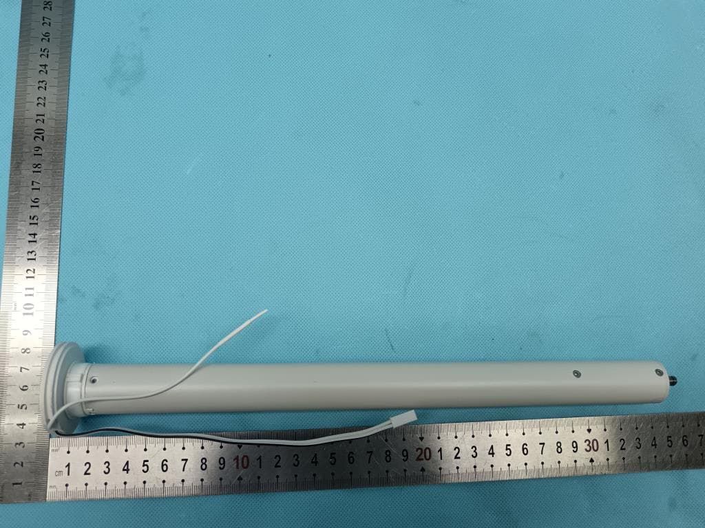
2AGGZ003B9ACA4C
Jul 08, 2023DC 1.1Nm ARC Motor
Equipment Class
DSR - Part 15 Remote Control/Security Device Transceiver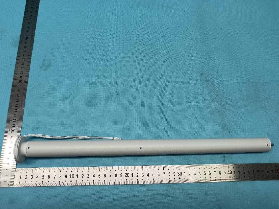
2AGGZ003B9ACA4D
Jul 08, 2023DC 2.0Nm ARC Motor
Equipment Class
DSR - Part 15 Remote Control/Security Device Transceiver