2AHRD-DB1305CUWireless Adapter
Shenzhen EDUP Electronics Technology Co.,Ltd.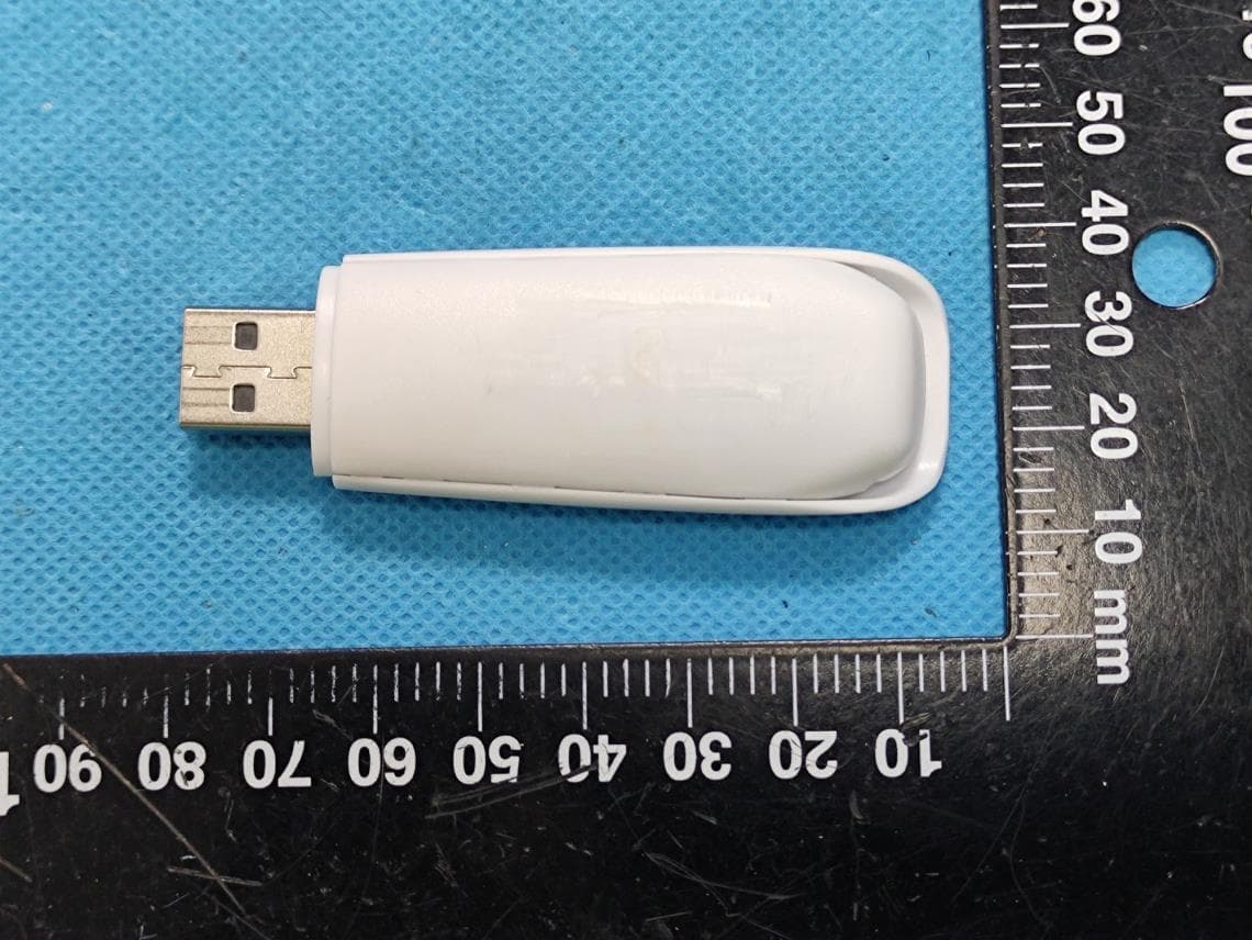
Click to zoom
Application Details
- Equipment Class
- NII - Unlicensed National Information Infrastructure TX
- Date of Grant
- Aug 17, 2022
- Application Purpose
- Original Equipment
- Date of Application
- Aug 17, 2022
- Equipment Note
- Wireless Adapter
- Frequency Range
- 5745.00000000 - 5825.00000000
- Country
- China
Documents & Files
Document Text
Text extracted from the exhibit documents filed with the FCC. Open a document above to read the original.
Users Manual
01. Put in the CD and find windows file “windows (xp,vista,win7,win8,win10)” andSetup.exe. 02. Double click Setup.exe file, Software begin to initialization,then click the “Next”.There shows the installation progress. 03. Do not interrupt installation, Click “finish” to finish the driver installation.The computer automatically restart. Wireless connection (two ways to realize Wireless connection 1 04.Plug the Wireless USB Adapter into the USB port of your PC 05.Click Icon in the Windows system tray, which locates in the bottom-right corner of your computer screen or double click , and pops up a message and click”Available Network” Double-click the utility icon or right click the icon ,and the Wireless Network Connection window appears then double click the SSID you preferred. 12345 USB Wireless Adapter NoteThis Manual based on Windows7 Quick Installation Guide 6 789 10111213 Note:if there is no icon , please find it in the on right buttom,it have been hide as following pictures shows: Wireless Connection2. 06. Click Iconwhich locates in the bottom-right corner of your computer screen,click the wireless network list and choose the SSID you preferred. and double click (Or click “Connect”). Type the encryption key and then click “ok”. Type the encryption key that you wrote down earlier in both the Network key and Confirm network key boxes, and then click “ok”. FCC Statement RF Exposure Information SAR tests are conducted using standard operating positions accepted by the FCC with the device transmitting at its highest certified power level in all tested frequency bands, although the SAR is determined at the highest certified power level, the actual SAR level of the devide while operating can be well below the maximum value. Before a new device is a available for sale to the public, it must be tested and certified to the FCC that it does not exceed the exposure limit established by the FCC, Tests for each device are performed in positions and locations as required by the FCC. For body worn operation, this device has been tested and meets the FCC RF exposure guidelines when used with an accessory designated for this product or when used with an accessory that Contains no metal and that positions a minimum of 5mm from the body. Non‐compliance with the above restrictions may result in violation of RF exposure guidelines. 1. This device complies with Part 15 of the FCC Rules. Operation is subject to the following two conditions: (1) This device may not cause harmful interference. (2) This device must accept any interference received, including interference that may cause undesired operation. 2. Changes or modifications not expressly approved by the party responsible for compliance could void the user's authority to operate the equipment. NOTE: This equipment has been tested and found to comply with the limits for a Class B digital device, pursuant to Part 15 of the FCC Rules. These limits are designed to provide reasonable protection against harmful interference in a residential installation. This equipment generates uses and can radiate radio frequency energy and, if not installed and used in accordance with the instructions, may cause harmful interference to radio communications.. However, there is no guarantee that interference will not occur in a particular installation. If this equipment does cause harmful interference to radio or television reception, which can be determined by turning the equipment off and on, the user is encouraged to try tocorrect the interference by one or more of the following measures: Reorient or relocate the receiving antenna. Increase the separation between the equipment and receiver. Connect the equipment into an outlet on a circuit different from that to which the receiver is connected. Consult the dealer or an experienced radio/TV technician for help.
External Photos
EXHIBIT B - EUT EXTERNAL PHOTOGRAPHS
Internal Photos
EXHIBIT C - EUT INTERNAL PHOTOGRAPHS Antenna 2.4G Antenna 5G Antenna
RF Exposure Info
SAR TEST REPORT Applicant: Shenzhen EDUP Electronics Technology Co.,Ltd. Address: 6 Floor, #6 Building, No.48, Kangzheng Road Liantang Industrial Area, Buji Town,Shenzhen,China FCC ID: 2AHRD-DB1305CU Product Name: Wireless Adapter Tested Model: EP-DB1305CU Multiple Models: EP-DB1305, 1002216-0000 Standard(s): 47 CFR Part 2(2.1093) The above equipment has been tested and found compliant with the requirement of the relative standards by China Certification ICT Co., Ltd (Dongguan) Report Number: CR22030054-20 Date Of Issue: 2022-05-22 Reviewed By: Sun Zhong Title: Manager Test Laboratory: China Certification ICT Co., Ltd (Dongguan) No. 113, Pingkang Road, Dalang Town, Dongguan, Guangdong, China Tel: +86-769-82016888 China Certification ICT Co., Ltd (Dongguan) Report No.: CR22030054-20 Page 2 of 50 SAR TEST RESULTS SUMMARY Operation Frequency Bands Highest Reported 1g SAR (W/kg) Limits (W/kg) Close to Body (Gap 5mm) WLAN 2.4G 0.25 1.6 WLAN 5.8G 1.19 Maximum Simultaneous Transmission SAR Items Close to Body (Gap 5mm) Limits Sum SAR(W/kg) / 1.6 SPLSR / 0.04 EUT Received Date: 2022/03/19 Test Date: 2022/04/23 Test Result: Pass China Certification ICT Co., Ltd (Dongguan) Report No.: CR22030054-20 Page 3 of 50 Test Facility The Test site used by China Certification ICT Co., Ltd (Dongguan) to collect test data is located on the No. 113, Pingkang Road, Dalang Town, Dongguan, Guangdong, China. The lab has been recognized as the FCC accredited lab under the KDB 974614 D01 and is listed in the FCC Public Access Link (PAL) database, FCC Registration No. : 442868, the FCC Designation No. : CN1314. The lab has been recognized by Innovation, Science and Economic Development Canada to test to Canadian radio equipment requirements, the CAB identifier: CN0123. Declarations China Certification ICT Co., Ltd (Dongguan) is not responsible for the authenticity of any test data provided by the applicant. Data included from the applicant that may affect test results are marked with a triangle symbol “▲”. Customer model name, addresses, names, trademarks etc. are not considered data. Unless otherwise stated the results shown in this test report refer only to the sample(s) tested. This report cannot be reproduced except in full, without prior written approval of the Company. This report is valid only with a valid digital signature. The digital signature may be available only under the Adobe software above version 7.0. This report may contain data that are not covered by the accreditation scope and shall be marked with an asterisk “★”. China Certification ICT Co., Ltd (Dongguan) Report No.: CR22030054-20 Page 4 of 50 CONTENTS SAR TEST RESULTS SUMMARY .............................................................................................. 2 TEST FACILITY .......................................................................................................................................... 3 DECLARATIONS .......................................................................................................................................... 3 1. GENERAL INFORMATION .................................................................................................... 6 1.1 PRODUCT DESCRIPTION FOR EQUIPMENT UNDER TEST (EUT) ....................................................... 6 1.2 TEST SPECIFICATION, METHODS AND PROCEDURES ........................................................................ 7 1.3 SAR LIMTS ........................................................................................................................................... 8 2. SAR MEASUREMENT SYSTEM ............................................................................................ 9 3. EQUIPMENT LIST AND CALIBRATION .......................................................................... 16 3.1 EQUIPMENTS LIST & CALIBRATION INFORMATION ....................................................................... 16 4. SAR MEASUREMENT SYSTEM VERIFICATION ........................................................... 17 4.1 LIQUID VERIFICATION ...................................................................................................................... 17 4.2 SYSTEM ACCURACY VERIFICATION ................................................................................................. 18 4.3 SAR SYSTEM VALIDATION DATA ............................................................................................. 19 5. EUT TEST STRATEGY AND METHODOLOGY .............................................................. 21 5.1 TEST POSITIONS FOR DEVICE OPERATING NEXT TO A PERSON’S EAR ......................................... 21 5.2 CHEEK/TOUCH POSITION .................................................................................................................. 22 5.3 EAR/TILT POSITION ........................................................................................................................... 22 5.4 TEST POSITIONS FOR BODY-WORN AND OTHER CONFIGURATIONS ................................................ 23 5.5 TEST DISTANCE FOR SAR EVALUATION .......................................................................................... 24 5.6 SAR EVALUATION PROCEDURE ....................................................................................................... 25 6. CONDUCTED OUTPUT POWER MEASUREMENT ........................................................ 26 6.1 TEST PROCEDURE .............................................................................................................................. 26 6.3 MAXIMUM TARGET OUTPUT POWER ............................................................................................... 26 6.4 TEST RESULTS: .................................................................................................................................. 27 7. STANDALONE SAR TEST EXCLUSION CONSIDERATIONS ...................................... 28 ANTENNA DISTANCE TO EDGE ....................…
Text truncated - open the document above for the full version.
RF Exposure Info
APPENDIX C PROBE CALIBRATION CERTIFICATES DIPOLE CALIBRATION CERTIFICATES
Test Report
TEST REPORT Applicant: Shenzhen EDUP Electronics Technology Co.,Ltd. Address: 6 Floor, #6 Building, No.48, Kangzheng Road Liantang Industrial Area, Buji Town,Shenzhen,china FCC ID: 2AHRD-DB1305CU Product Name: Wireless Adapter Standard(s): 47 CFR Part 15, Subpart E(15.407) ANSI C63.10-2013 KDB 789033 D02 General U-NII Test Procedures New Rules v02r01 The above equipment has been tested and found compliant with the requirement of the relative standards by China Certification ICT Co., Ltd (Dongguan) Report Number: CR22030054-00B Date Of Issue: 2022-05-23 Reviewed By: Sun Zhong Title: Manager Test Laboratory: China Certification ICT Co., Ltd (Dongguan) No. 113, Pingkang Road, Dalang Town, Dongguan, Guangdong, China Tel: +86-769-82016888 China Certification ICT Co., Ltd (Dongguan) Report No.: CR22030054-00B Page 2 of 50 Test Facility The Test site used by China Certification ICT Co., Ltd (Dongguan) to collect test data is located on the No. 113, Pingkang Road, Dalang Town, Dongguan, Guangdong, China. The lab has been recognized as the FCC accredited lab under the KDB 974614 D01 and is listed in the FCC Public Access Link (PAL) database, FCC Registration No. : 442868, the FCC Designation No. : CN1314. The lab has been recognized by Innovation, Science and Economic Development Canada to test to Canadian radio equipment requirements, the CAB identifier: CN0123. Declarations China Certification ICT Co., Ltd (Dongguan) is not responsible for the authenticity of any test data provided by the applicant. Data included from the applicant that may affect test results are marked with a triangle symbol “▲”. Customer model name, addresses, names, trademarks etc. are not considered data. Unless otherwise stated the results shown in this test report refer only to the sample(s) tested. This report cannot be reproduced except in full, without prior written approval of the Company. This report is valid only with a valid digital signature. The digital signature may be available only under the Adobe software above version 7.0. This report may contain data that are not covered by the accreditation scope and shall be marked with an asterisk “★”. China Certification ICT Co., Ltd (Dongguan) Report No.: CR22030054-00B Page 3 of 50 CONTENTS TEST FACILITY .......................................................................................................................................... 2 DECLARATIONS .......................................................................................................................................... 2 1. GENERAL INFORMATION .................................................................................................... 5 1.1 PRODUCT DESCRIPTION FOR EQUIPMENT UNDER TEST (EUT) ....................................................... 5 1.2 DESCRIPTION OF TEST CONFIGURATION ........................................................................................... 7 1.2.2 Support Equipment List and Details .............................................................................................................. 7 1.2.3 Support Cable List and Details ...................................................................................................................... 7 1.2.4 Block Diagram of Test Setup ......................................................................................................................... 8 1.3 MEASUREMENT UNCERTAINTY .......................................................................................................... 9 2. SUMMARY OF TEST RESULTS .......................................................................................... 10 3. REQUIREMENTS AND TEST PROCEDURES .................................................................. 11 3.1 AC LINE CONDUCTED EMISSIONS .................................................................................................... 11 3.1.1 Applicable Standard ..................................................................................................................................... 11 3.1.2 EUT Setup .................................................................................................................................................... 12 3.1.3 EMI Test Receiver Setup ............................................................................................................................. 12 3.1.4 Test Procedure ............................................................................................................................................. 13 3.1.5 Corrected Amplitude & Margin Calculation ................................................................................................ 13 3.2 RADIATION SPURIOUS EMISSIONS .................................................................................................... 14 3.2.1 Applicable Standard ..................................................................................................................................... 14 3.2.2 EUT Setup .................................................................................................................................................... 15 3.2.3 EMI Test Receiver & Spectrum Analyzer Setup ......................................................................................... 16 3.2.4 Test Procedure ............................................................................................................................................. 17 3.2.5 Corrected Amplitude & Margin Calculation ................................................................................................ 17 3.3 EMISSION BANDWIDTH: .................................................................................................................... 18 3.3.1 Applicable Standard ..................................................................................................................................... 18 3.3.2 EUT Setup .................................................…
Text truncated - open the document above for the full version.
Test Setup Photos
EXHIBIT D - TEST SETUP PHOTOGRAPHS Conducted Emissions Front View Conducted Emissions Side View Radiated Emission Below 1GHz View Radiated Emission Above 1GHz View
Test Setup Photos
Report No.: CR22030054-20 Page 1 of 4 APPENDIX B EUT TEST POSITION PHOTOS Liquid depth ≥ 15cm Phantom: Twin SAM; Type: Twin SAM V5.0; Serial: TP:1412 Report No.: CR22030054-20 Page 2 of 4 Horizontal-Down Adding USB Extension Cable Setup Photo(5 mm) Horizontal-Up Setup Photo(5 mm) 5mm 5mm Report No.: CR22030054-20 Page 3 of 4 Vertical-Front Setup Photo(5 mm) Vertical-Back Adding USB Extension Cable Setup Photo(5 mm) 5 mm 5mm Report No.: CR22030054-20 Page 4 of 4 Body Top Setup Photo (5 mm) 5mm
Contact Information
Applicant
Zhou Chunping
Test Firm
CHINA CERTIFICATION ICT CO., LTD (DONGGUAN)Tanie Ou
[email protected]0086 0769 86858888
Technical Specifications
| # | Rule Parts | Frequency Range | Power Output |
|---|---|---|---|
| 1 | 15E | 5.75 GHz - 5.83 GHz | 10.00 mW |
Other Applications from Shenzhen EDUP Electronics Technology Co.,Ltd.
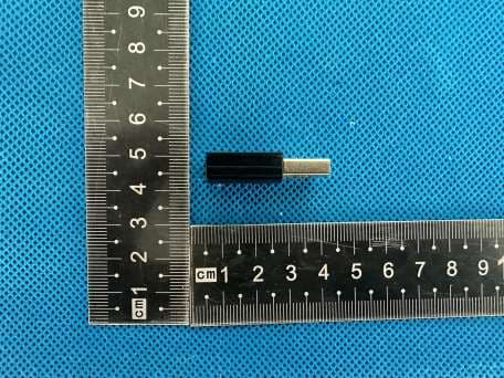
2AHRDEP-AC1633
Mar 09, 2024USB WiFi Adapter
Equipment Class
DTS - Digital Transmission System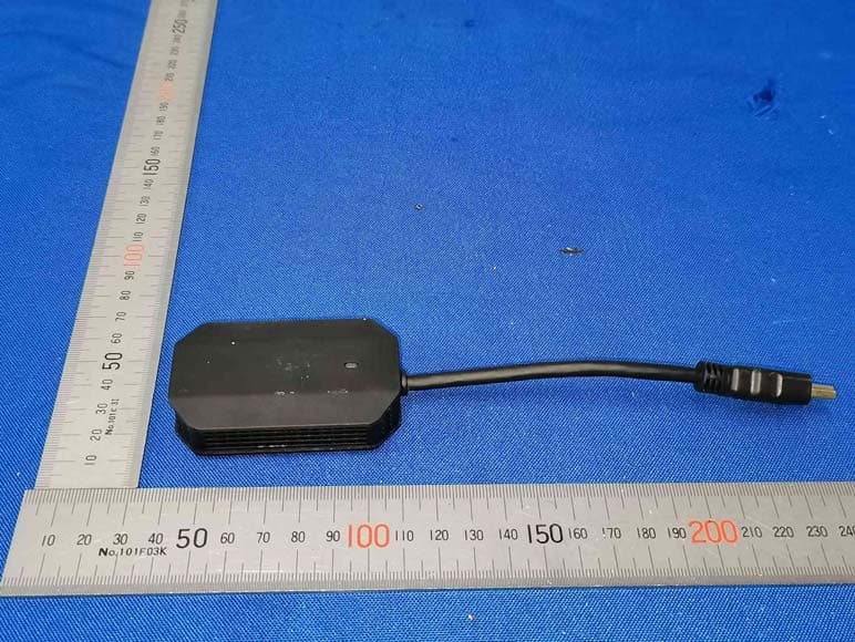
2AHRD-EHWD9905
May 09, 2023Co-screen Device
Equipment Class
DTS - Digital Transmission System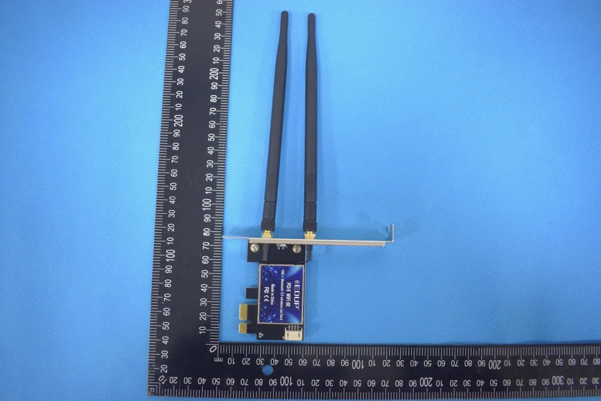
2AHRD-EPEP9651
Mar 04, 2022Bluetooth PCI-E WiFi Card
Equipment Class
NII - Unlicensed National Information Infrastructure TX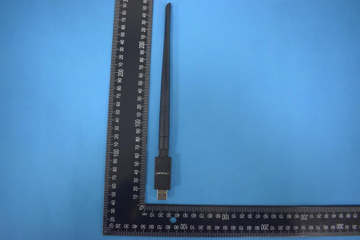
2AHRD-EPAC1690
Mar 04, 20221200M Wireless Adapter with Bluetooth Function
Equipment Class
DTS - Digital Transmission System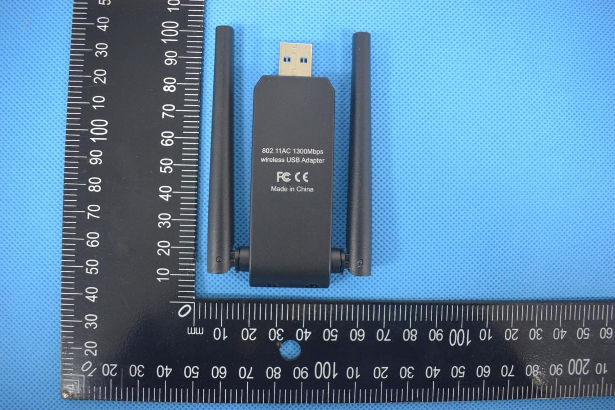
2AHRD-EPAC1698
Mar 04, 20221300M Wireless Adapter
Equipment Class
NII - Unlicensed National Information Infrastructure TX