2AJGM-P53UGMRS TWO WAY RADIO
PO FUNG ELECTRONIC (HK) INTERNATONAL GROUP COMPANY LIMITED
Click to zoom
Application Details
- Equipment Class
- TNF - Licensed Non-Broadcast Transmitter Held to Face
- Date of Grant
- Jul 15, 2020
- Application Purpose
- Original Equipment
- Date of Application
- Jul 15, 2020
- Equipment Note
- GMRS TWO WAY RADIO
- Frequency Range
- 467.65000000 - 467.65000000
- Country
- Hong Kong
Documents & Files
Document Text
Text extracted from the exhibit documents filed with the FCC. Open a document above to read the original.
Users Manual
User Manual(FCC Version Draft) This manual is applicable to the following product: P53U,BF-1903,P53UH,P53UL,P53X,P54U,BF-1904,P54UM,P54G,P54X ATTENTION This is a multi-task GMRS transceiver. Combining the latest technology in radio communication along with a sturdy mechanical frame, Radio is the ideal and effective solution for the professionals who need to stay in touch with the working team (in construction sites, buildings, shows, trade fairs or hotels) or for leisure users that just want to keep up with friends and family. To help you ward off bodily injury or property loss that may arise from improper operation, please read all the information carefully before using our products. Use the two way radio in the environment with the temperature between -10°C ~ 40°C, otherwise, it may damage your two way radio. It can be operating under 2000m. Long-term high-power channel transmitter, the radio fever is a normal phenomenon, but we do not recommend you for a long time at high power transmitter, do not use the radios in without installing an antenna or antenna damaged. Intended Use Our products are designed to provide reliable wireless communication services for users across many industry sectors. In order to use the products safely and to achieve the best performance, they must be used as intended. The operator of the product is responsible for damage to the product or damage caused by the product if the product was used beyond the intended use instructions. Intended use includes that: • The product is used by users who have full knowledge of its RF exposure and can exercise control over their RF exposure to meet the occupational limits in FCC/ICNIRP and international standards. • All the security instructions set forth in this document are always heeded. • The general, national and in-house safety regulations are heeded. • The product is exclusively used with the frequencies licensed by the respective authority. • The product is configured appropriately by the dealer. Besides, intended use also requires the product operator to be well-trained and to be familiar with the applicable standards, regulations and provisions. REGULATORY Information This equipment has been tested and found to comply with the limits for a Class B digital device, pursuant to Part 15 of FCC Rules. These limits are designed to provide reasonable protection against harmful interference in a residential installation. This equipment generates and can radiate radio frequency energy. If not installed and used in accordance with the instructions, it may cause harmful interference to radio communications. However, there is no guarantee that interference will not occur in a particular installation. Verification of harmful interference by this equipment to radio or television reception can be determined by turning it off and then on. The user is encouraged to try to correct the interference by one or more of the following measures: - Reorient or relocate the receiving antenna. - Increase the separation between the equipment and receiver. - Connect the equipment into an outlet on a circuit different from that to which the receiver is connected. - Consult the dealer or an experienced radio/TV technician for help. Changes or modifications not expressly approved by the party responsible for compliance could void the user's authority to operate the equipment. This device complies with Part 15 of the FCC Rules. Operation is subject to the following two conditions: (1) This device may not cause harmful interference, and (2) This device must accept any interference received, including interference that may cause undesired operation. FCC License required for GMRS operation (Only applicable for GMRS radio use in the US) The radios operate on GMRS frequencies which require an FCC license. You must be licensed prior to operating on channels 1~16, which comprise the GMRS channels of the radio. Serious penalties could result from unlicensed used of GMRS channels,in viola-tion of FCC rules,as stipulated in the communications acts secitions 501 and 502 (amended). User Manual(FCC Version Draft) This manual is applicable to the following product: P53U,BF-1903,P53UH,P53UL,P53X,P54U,BF-1904,P54UM,P54G,P54X You will be issued a call sign by the FCC which should be used for sation identification when operating the radio on GMRS channels. You should also cooperate by engaging in permissible transmissions only,avoiding channel interference with orher GMRS users,and being prudent with the length of your transmission time. To obtain a license or ask questions about the license application,contact the FCC at 1-88-CALL FCC or go to the fcc website:http://www.fcc.gov andrequestfom 605. Important: Any changes or modifications not expressly approved by the party responsible for compliance could void the user's authority to operate this device. Your radio is set up to transmit a regulated signal on an assigned frequency. It is against the law to alter or adjust the settings inside the radio to exceed those limitations. Any adjustments to your radio must be made by qualified technicians. To be safe and sure: • Never open your radio’s case. • Never change or replace anything in your radio except the battery. Your radio might cause TV or radio interference even when it is operating properly. To determine whether Your radio is causing the interference, turn it off. If the interference goes away, your radio is causing it. Try to eliminate the interference by moving your radio away from the receiver. If you cannot eliminate the interference, the FCC requires that you stop using the radio. Hazardous Environments: Do not operate the radio in hazardous environments. Explosion or fire may result. Do not operate the radio near unshielded electrical blasting caps. Under certain conditions, radios can interfere with blasting operations and may cause an explosion. Turn your radio OFF to prevent accidental transmission when in a blasting area or in areas posted: "Turn of…
Text truncated - open the document above for the full version.
Cover Letter(s)
PO FUNG ELECTRONIC(HK) INTERNATIOANL GROUP COMPANY 3/F FULOK BLDG 131-133 WING LOK ST SHEUNG WAN, Hong Kong Agent Authorization Company: PO FUNG ELECTRONIC(HK) INTERNATIOANL GROUP COMPANY Address: 3/F FULOK BLDG 131-133 WING LOK ST SHEUNG WAN, Hong Kong Product Name: TWO WAY RADIO Model Number(s): P53U, BF-1903, P53UH, P53UL, 53X Product Description: GMRS TWO WAY RADIO We authorize MiCOM Labs Inc., 575 Boulder Court, Pleasanton, California 94566, USA, to act on our behalf on all matters concerning the certification of above named equipment. We declare that MiCOM Labs Inc. is allowed to forward all information related to the approval and certification of equipment to the regulatory agencies as required and to discuss any issues concerning the approval application. Any and all acts carried out by MiCOM Labs on our behalf shall have the same effect as acts of our own. Signature: Date: Jun. 24, 2020 Name: Peter Wang Title: General Manager Company: PO FUNG ELECTRONIC(HK) INTERNATIOANL GROUP COMPANY
Cover Letter(s)
PO FUNG ELECTRONIC(HK) INTERNATIOANL GROUP COMPANY 3/F FULOK BLDG 131-133 WING LOK ST SHEUNG WAN, Hong Kong Jun. 24, 2020 To: Federal Communication Commission Equipment Authorization Branch 7435 Oakland Mills Road Columbia, MD 21046 Subject: Attestation statement regarding the Mobile Radio frequency Applicant: PO FUNG ELECTRONIC(HK) INTERNATIOANL GROUP COMPANY 3/F FULOK BLDG 131-133 WING LOK ST SHEUNG WAN, Hong Kong TYPE OF QEUIPMENT: Licensed Non-Broadcast Transmitter Held to Face FCC ID: 2AJGM-P53U Dear Sir or Madam I attest that the product has one antenna, one battery capacity, one body-worn and audio accessory. And that the product could program the frequency on computer through interface by manufacturer, is incapable of tuning, or readily being altered, by the end-user. Please contact the undersigned if you have any questions or need any further information. Regards Signature: Name, Job Title and Dept.: Peter Wang / General Manager
Cover Letter(s)
PO FUNG ELECTRONIC(HK) INTERNATIOANL GROUP COMPANY 3/F FULOK BLDG 131-133 WING LOK ST SHEUNG WAN, Hong Kong Jun. 24, 2020 Office of Engineering Technology Federal Communications Commission 7435 Oakland Mills Road Columbia, MD 21046 USA Subject: Explanation of differences between product types FCC ID: 2AJGM-P53U Models: P53U, BF-1903, P53UH, P53UL, 53X To Whom It May Concern: We, The PO FUNG ELECTRONIC(HK) INTERNATIOANL GROUP COMPANY hereby declare that the model : BF-1903, P53UH, P53UL, 53X is identical with the model : P53U, except the shell design differences & models, trademarks are different. Except for the different above, no other modification is performed. Sincerely, PO FUNG ELECTRONIC(HK) INTERNATIOANL GROUP COMPANY Signature: [Peter Wang, General Manager]
Cover Letter(s)
PO FUNG ELECTRONIC(HK) INTERNATIOANL GROUP COMPANY 3/F FULOK BLDG 131-133 WING LOK ST SHEUNG WAN, Hong Kong Office of Engineering Technology Federal Communications Commission 7435 Oakland Mills Road Columbia, MD 21046 USA Date: Jun. 24, 2020 Subject; Request for Confidentiality FCC ID: 2AJGM-P53U To Whom It May Concern, Pursuant to the provisions of the Commission’s rules Title 47 Sections §0.457 and §0.459, we are requesting the Commission to withhold the following attachment(s) as confidential documents from public disclosure indefinitely. These documents contain detailed system and equipment descriptions and are considered as proprietary information in operation of the equipment. The public disclosure of these documents might be harmful to our company and would give competitors an unfair advantage in the market. Schematic Diagram Block Diagram Parts List Operational Description Tune-up Procedure It is our understanding that all measurement test reports, FCC ID label format and correspondence during the certification review process cannot be granted as confidential documents and this information will be available for public review once the grant of equipment authorization is issued. Sincerely, Signature: Name: Peter Wang Title: General Manager
External Photos
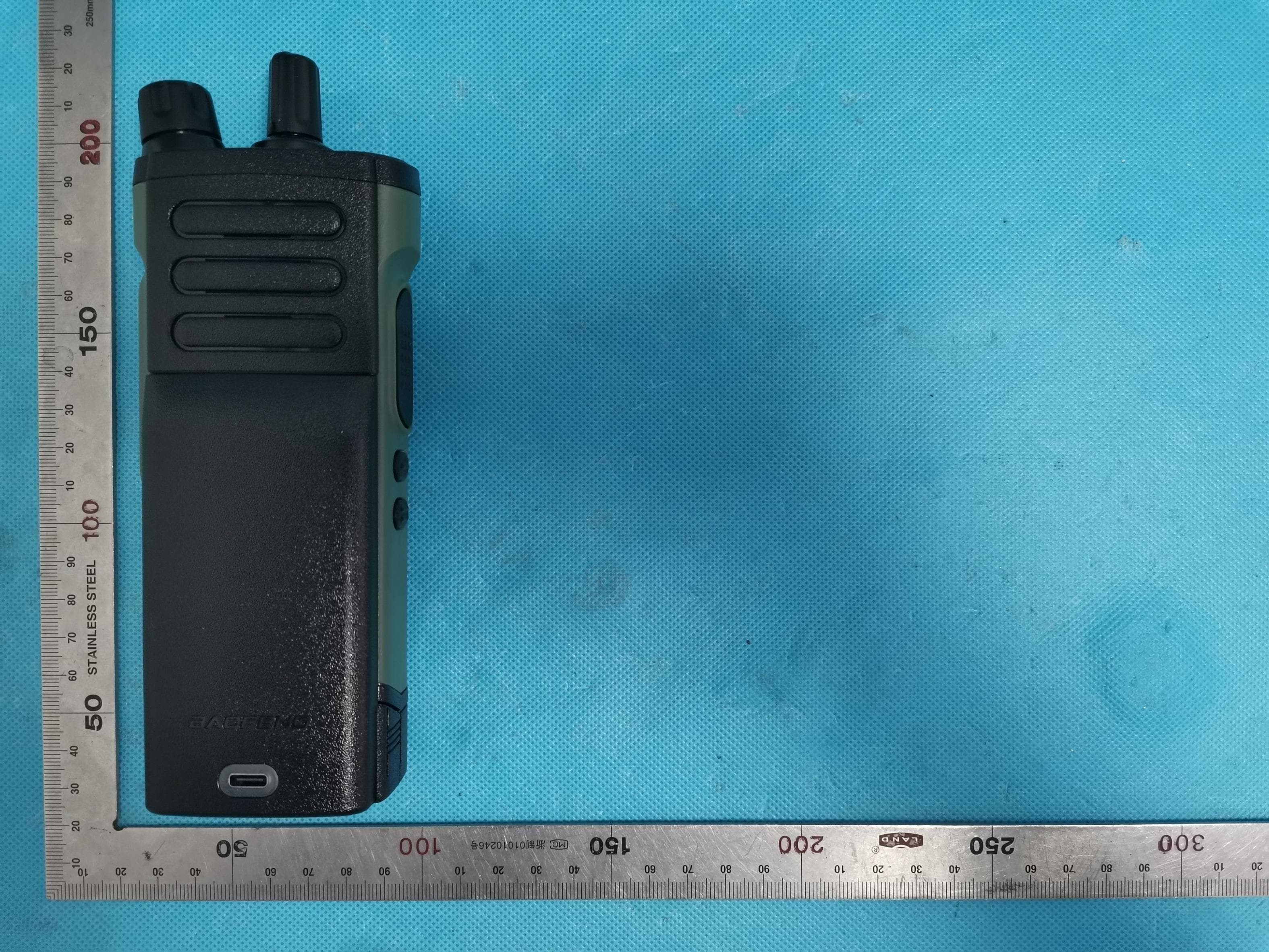
External Photos All VIEW OF EUT TOP VIEW OF EUT BOTTOM VIEW OF EUT FRONT VIEW OF EUT BACK VIEW OF EUT LEFT VIEW OF EUT RIGHT VIEW OF EUT
ID Label/Location Info
FCC ID Label Location 15mm*15mm FCC ID: 2AJGM-P53U
ID Label/Location Info
PO FUNG ELECTRONIC(HK) INTERNATIOANL GROUP COMPANY 3/F FULOK BLDG 131-133 WING LOK ST SHEUNG WAN, Hong Kong Jun. 24, 2020 Statement We, PO FUNG ELECTRONIC(HK) INTERNATIOANL GROUP COMPANY (FCC ID: 2AJGM-P53U) puts the label inside the battery compartment of this device. It is visible to the users as they purchase the products and install the battery. Regards PO FUNG ELECTRONIC(HK) INTERNATIOANL GROUP COMPANY Contact person: Peter Wang Title: General Manager
Internal Photos
Internal Photos OPEN VIEW OF EUT(FIGURE 1) OPEN VIEW OF EUT(FIGURE 2) OPEN VIEW OF EUT(FIGURE 3) INTERNAL VIEW OF EUT(FIGURE 1) INTERNAL VIEW OF EUT(FIGURE 2) INTERNAL VIEW OF EUT(FIGURE 3) GMRS Antenna INTERNAL VIEW OF EUT(FIGURE 4) INTERNAL VIEW OF EUT(FIGURE 5) INTERNAL VIEW OF EUT(FIGURE 6)
RF Exposure Info
PROBE CALIBRATION DATA DIPOLE CALIBRATION DATA
RF Exposure Info
Page 1 of 46 SAR Test Report Report No.: AGC02294200402FH01 FCC ID : 2AJGM-P53U PRODUCT DESIGNATION : TWO WAY RADIO BRAND NAME : BAOFENG, POFUNG MODEL NAME : P53U, BF-1903, P53UH, P53UL, P53X APPLICANT : PO FUNG ELECTRONIC(HK) INTERNATIOANL GROUP COMPANY DATE OF ISSUE : Jun. 28,2020 STANDARD(S) : IEEE Std. 1528:2013 FCC 47 CFR Part 2§2.1093:2013 IEEE Std C95.1 ™-2005 IEC 62209-1: 2016 REPORT VERSION : V1.0 Attestation of Global Compliance(Shenzhen) Co., Ltd. CAUTION: This report shall not be reproduced except in full without the written permission of the test laboratory and shall not be quoted out of context. Report No.: AGC02294200402FH01 Page 2 of 46 Report Revise Record Report Version Revise Time Issued Date Valid Version Notes V1.0 / Jun. 28,2020 Valid Initial Release Report No.: AGC02294200402FH01 Page 3 of 46 Test Report Applicant Name PO FUNG ELECTRONIC(HK) INTERNATIOANL GROUP COMPANY Applicant Address 3/F FULOK BLDG 131-133 WING LOK ST SHEUNG WAN, Hong Kong Manufacturer Name PO FUNG ELECTRONIC(HK) INTERNATIOANL GROUP COMPANY Manufacturer Address 3/F FULOK BLDG 131-133 WING LOK ST SHEUNG WAN, Hong Kong Factory Name PO FUNG ELECTRONIC(HK) INTERNATIOANL GROUP COMPANY Factory Address 3/F FULOK BLDG 131-133 WING LOK ST SHEUNG WAN, Hong Kong Product Designation TWO WAY RADIO Brand Name BAOFENG, POFUNG Model Name P53U, BF-1903, P53UH, P53UL, P53X Different Description The same motherboard and specifications, only the shell design differences & models, trademarks are different. EUT Voltage DC7.4 V Applicable Standard IEEE Std. 1528:2013 FCC 47 CFR Part 2§2.1093:2013 IEEE Std C95.1 ™-2005 IEC 62209-1: 2016 Test Date May 23,2020 Report Template AGCRT- US -PTT/SAR (2018-02-02) Note: The results of testing in this report apply to the product/system which was tested only. Prepared By Jack Gui (Project Engineer) May 23,2020 Reviewed By Angela Li (Reviewer) Jun. 28,2020 Approved By Forrest Lei (Authorized Officer) Jun. 28,2020 Report No.: AGC02294200402FH01 Page 4 of 46 TABLE OF CONTENTS 1. SUMMARY OF MAXIMUM SAR VALUE ......................................................................................................... 5 2. GENERAL INFORMATION ............................................................................................................................... 6 2.1. EUT DESCRIPTION......................................................................................................................................... 6 3. SAR MEASUREMENT SYSTEM ........................................................................................................................ 7 3.1. THE SATIMO SYSTEM USED FOR PERFORMING COMPLIANCE TESTS CONSISTS OF FOLLOWING ITEMS .................. 7 3.2. COMOSAR E-FIELD PROBE .......................................................................................................................... 8 3.3. ROBOT .......................................................................................................................................................... 8 3.4. VIDEO POSITIONING SYSTEM .......................................................................................................................... 9 3.5. DEVICE HOLDER ............................................................................................................................................ 9 3.6. SAM TWIN PHANTOM ................................................................................................................................... 10 4. SAR MEASUREMENT PROCEDURE ............................................................................................................ 11 4.1. SPECIFIC ABSORPTION RATE (SAR) .............................................................................................................. 11 4.2. SAR MEASUREMENT PROCEDURE ................................................................................................................ 12 5. TISSUE SIMULATING LIQUID ....................................................................................................................... 14 5.1. THE COMPOSITION OF THE TISSUE SIMULATING LIQUID..................................................................................... 14 5.2. TISSUE DIELECTRIC PARAMETERS FOR HEAD AND BODY PHANTOMS ............................................................... 14 5.3. TISSUE CALIBRATION RESULT ....................................................................................................................... 15 6. SAR SYSTEM CHECK PROCEDURE ........................................................................................................... 16 6.1. SAR SYSTEM CHECK PROCEDURES ............................................................................................................. 16 7. EUT TEST POSITION ...................................................................................................................................... 18 7.1. BODY WORN POSITION ................................................................................................................................ 18 8. SAR EXPOSURE LIMITS ............................................................................................................................... 19 9. TEST FACILITY .............................................................................................................................................. 20 10. TEST EQUIPMENT LIST .............................................................................................................................. 21 11. MEASUREMENT UNCERTAINTY ................................................................................................................ 22 12. POWER MEASUREMENT ............................................................................................................................ 25 13. TEST RESULTS ...................................................................................…
Text truncated - open the document above for the full version.
Test Report
Page 1 of 49 FCC Part 95 Rules Test Report Report No.:AGC02294200402FE10 FCC ID : 2AJGM-P53U PRODUCT DESIGNATION : TWO WAY RADIO BRAND NAME : BAOFENG, POFUNG MODEL NAME : P53U, BF-1903, P53UH, P53UL, 53X APPLICANT : PO FUNG ELECTRONIC(HK) INTERNATIOANL GROUP COMPANY DATE OF ISSUE : Jun. 23, 2020 STANDARD(S) : FCC Part 95 Rules REPORT VERSION : V 1.0 Attestation of Global Compliance (Shenzhen) Co., Ltd CAUTION: This report shall not be reproduced except in full without the written permission of the test laboratory and shall not be quoted out of context. Report No.:AGC02294200402FE10 Page 2 of 49 Report Revise Record Report Version Revise Time Issued Date Valid Version Notes V1.0 / Jun. 23, 2020 Valid Initial release Report No.:AGC02294200402FE10 Page 3 of 49 VERIFICATION OF COMPLIANCE Applicant PO FUNG ELECTRONIC(HK) INTERNATIOANL GROUP COMPANY Address 3/F FULOK BLDG 131-133 WING LOK ST SHEUNG WAN, Hong Kong manufacturer PO FUNG ELECTRONIC(HK) INTERNATIOANL GROUP COMPANY Address 3/F FULOK BLDG 131-133 WING LOK ST SHEUNG WAN, Hong Kong Factory PO FUNG ELECTRONIC(HK) INTERNATIOANL GROUP COMPANY Address 3/F FULOK BLDG 131-133 WING LOK ST SHEUNG WAN, Hong Kong Product Designation: TWO WAY RADIO Brand Name: BAOFENG,POFUNG Test Model P53U Serial Model BF-1903, P53UH, P53UL, 53X Difference Description The same motherboard and specifications, only the shell design differences & models, trademarks are different Date of Test: Apr. 30, 2020~Jun. 23, 2020 WE HEREBY CERTIFY THAT: The above equipment was tested by Attestation of Global Compliance (Shenzhen) Co., Ltd. The data evaluation, test procedures, and equipment configurations shown in this report were made in accordance with the procedures given in TIA/EIA 603. The sample tested as described in this report is in compliance with the FCC Rules Part 95 requirements. The test results of this report relate only to the tested sample identified in this report. Prepared By Calvin Liu (Project Engineer) Jun. 23, 2020 Reviewed By Max Zhang (Reviewer ) Jun. 23, 2020 Approved By Forrest Lei Authorized Officer Jun. 23, 2020 Report No.:AGC02294200402FE10 Page 4 of 49 TABLE OF CONTENTS 1. GENERAL INFORMATION .............................................................................................................................. 6 1.1 PRODUCT DESCRIPTION .................................................................................................................... 6 1.2 RELATED SUBMITTAL(S) / GRANT (S) ................................................................................................ 8 1.3 TEST METHODOLOGY............................................................................................................................... 8 1.4 TEST FACILITY ........................................................................................................................................... 8 1.5 SPECIAL ACCESSORIES ........................................................................................................................... 8 1.6 EQUIPMENT MODIFICATIONS .................................................................................................................. 8 2. SYSTEM TEST CONFIGURATION .................................................................................................................. 9 2.1 EUT CONFIGURATION .............................................................................................................................. 9 2.2 EUT EXERCISE .......................................................................................................................................... 9 2.3 CONFIGURATION OF TESTED SYSTEM ............................................................................................... 10 3. SUMMARY OF TEST RESULTS .................................................................................................................... 11 4. DESCRIPTION OF TEST MODES ................................................................................................................. 14 5. FREQUENCY TOLERANCE .......................................................................................................................... 15 5.1 PROVISIONS APPLICABLE ..................................................................................................................... 15 5.2 MEASUREMENT PROCEDURE .............................................................................................................. 15 5.3 TEST SETUP BLOCK DIAGRAM ............................................................................................................. 16 5.4TEST RESULT ............................................................................................................................................ 17 6. EMISSION BANDWIDTH ............................................................................................................................... 19 6.1 PROVISIONS APPLICABLE ..................................................................................................................... 19 6.2 MEASUREMENT PROCEDURE .............................................................................................................. 19 6.3 TEST SETUP BLOCK DIAGRAM ............................................................................................................. 20 6.4 MEASUREMENT RESULT ........................................................................................................................ 23 7. UNWANTED RADIATION ............................................................................................................................... 25 7.1 PROVISIONS APPLICABLE ..................................................................................................................... 25 7.2 MEASUREMENT PROCEDURE .............................................................................................................. 25 7.3 TEST SETUP BLOCK DIAG…
Text truncated - open the document above for the full version.
Test Setup Photos
Test Setup Photos RADIATED EMISSION TEST SETUP
Test Setup Photos
Test Setup Photos Face Up with 2.5 cm Separation Distance. Body Back Touch with all accessories The thickness of EUT is 3.5 cm 25mm Note : The headset is just for testing. This tested and electrically similar headsets may be used. DEPTH OF THE LIQUID IN THE PHANTOM—ZOOM IN Note:The position used in the measurement were according to IEEE 1528-2013 450MHz body
Contact Information
Applicant
Peter Wang
Technical Contact
Test Firm
Attestation of Global Compliance (Shenzhen) Co., LDoris Li
[email protected]+86-755-25234088
Technical Specifications
| # | Rule Parts | Frequency Range | Power Output | Emission | Tolerance |
|---|---|---|---|---|---|
| 3 | 95E | 467.65 MHz - 467.65 MHz | 4.8641 W | 10K1F3E | 1.06 ppm |
Other Applications from PO FUNG ELECTRONIC (HK) INTERNATONAL GROUP COMPANY LIMITED
2AJGM-GM32
May 14, 2026GMRS Two Way Radio
Equipment Class
DTS - Digital Transmission System
2AJGM-AT2
Apr 13, 2026Two Way Radio
Equipment Class
DTS - Digital Transmission System
2AJGM-M4
Dec 29, 2025Two Way Radio
Equipment Class
TNF - Licensed Non-Broadcast Transmitter Held to Face
2AJGM-W31S
Dec 08, 2025Two Way Radio
Equipment Class
TNF - Licensed Non-Broadcast Transmitter Held to Face
2AJGM-888S
Oct 14, 2024TWO-WAY RADIO
Equipment Class
TNF - Licensed Non-Broadcast Transmitter Held to Face