2AJJ2-DETECTORMETAL DETECTOR
NOKTA MUHENDISLIK A.S.
Click to zoom
Application Details
- Equipment Class
- DXX - Part 15 Low Power Communication Device Transmitter
- Date of Grant
- Jul 09, 2021
- Application Purpose
- Original Equipment
- Date of Application
- Jul 09, 2021
- Equipment Note
- METAL DETECTOR
- Frequency Range
- 2440.00000000 - 2460.00000000
- Company
- NOKTA MUHENDISLIK A.S.
- Country
- Turkey
Documents & Files
Document Text
Text extracted from the exhibit documents filed with the FCC. Open a document above to read the original.
Users Manual
Turning On/Off the Device To turn on the device, press and hold the On/Off button until the bar starts filling up. To turn off the device, press and hold the button until the display light turns off. Sensitivity This is the depth setting of the device. It is also used to eliminate the ambient electromagnetic signals from the surrounding environment and noise signals transmitted from ground. Sensitivity setting consists of 8 levels and is pre-defined for each mode. Each mode starts with its default sensitivity setting and it can be manually modified when necessary. Note : If the ground is highly mineralized causing the device to overload, decrease the Sensitivity until the overload warning icon disappears from the screen. Pinpoint Pinpoint is to find the center or the exact location of a detected target. To perform pinpoint : 1- After a target is detected, move the search coil aside where there is no target response and push the Pinpoint button . 2- Keep the button pressed down and bring the search coil closer to the target slowly and parallel to the ground. 3- Signal sound becomes stronger and changes in pitch while getting closer to the target center. In addition, the bar on screen will rise or fall based on signal strength. 4- Mark the position which provides the loudest sound using a tool or your foot. 5- Repeat the above procedure by changing your direction 90°. Actions to be performed from a couple of different directions will narrow the target area and provide you with the most exact details of the target location. Frequency Shift It is used to eliminate the electromagnetic interference that the device receives from another detector which operates in the same frequency range nearby or from the surroundings. If too much noise is received when the search coil is lifted in the air, this may be caused by the local electromagnetic signals or excessive sensitivity settings. To shift the frequency, press and hold the M button for 3 seconds while the device is on. The frame around the search modes icon will start blinking. Change the frequency using the sensitivity +/- buttons. Note : If no button is pressed for 5 seconds, the screen will time out and the device will revert back to the main screen. Frequency shift will be reflected on the left side of the bar. The left side of the bar will start filling up / falling each time you press the sensitivity +/- buttons. Frequency shift consists of 10 steps and 5 is the central frequency. IMPORTANT! At each power up, the frequency shift setting will start at the central frequency of 5. Search Modes There are 2 search modes: All Metal and Discrimination. Press the M button to select the mode. All Metal Mode In this mode, the device does not provide audio tone discrimination and gives the same audio tone for all types of targets. Discrimination Mode In this mode, the device does NOT provide any audio tone for ferrous metals and it provides a high tone for non-ferrous metals. In both search modes: When the device detects a ferrous metal, the left side of the bar fills up in proportion to the strength of the target signal. When the device detects a non-ferrous metal, the right side of the bar fills up in proportion to the strength of the target signal. 1) On / Off Button 2) Search Mode Button 3) Search Modes 4) Pinpoint Button 5) Volume Buttons 6) Sensitivity Buttons 7) Signal Strength Bar 8) Warning Icons 9) Battery Icon 10) Wireless Connection Icon Control Display Illumination LEDs It is the flashlight used for lighting the area you are scanning while detecting at night or in dark locations. To activate the LEDs, while the detector is on, press the pinpoint and volume minus (-) buttons at the same time. Repeat the same to turn them off. LEDs do not operate when the device is off. It is recommended to turn them on only when necessary since they consume extra battery power. Volume Press the + or - button to adjust the volume. QUICK GUIDE 2 1 7 8 9 10 4 56 3 Assembly (2) To join the middle rod with the upper and lower rods, open the lever latches and engage the pieces together. After adjusting the length of the device to your height, press the latches to secure. (1) After inserting the washers on the lower shaft, place the lower shaft in its location on the search coil. Secure by tightening the screw and nut. Do not overtighten. (3) Wind the search coil cable on the shaft without stretching too much. Then, plug the connector to the search coil input socket on the system box and secure by tightening the nut. While tightening, you may hear clicks indicating that the connector is secured. (4) To adjust the armrest to your comfort, push the red lock forward. Adjust it by sliding it up or down and secure by pushing the red lock in the opposite direction. Insert the armrest strap as shown in the picture and adjust it to your arm size and tighten. Warning Icons Low Battery Warning Battery icon on the display shows the battery life status. When the charge decreases, the bars inside the battery icon decrease, too. When the battery is depleted, the battery icon will start flashing. Check Coil It indicates an interruption in the search coil transmitter signal. The search coil connector may be unattached, loose or disconnected or the search coil may have a defect. If the issue continues when you change the search coil, there may be an issue in the coil control circuit. Overload Shallow and/or large targets may cause an overload and the device starts to generate a continuous sound which resembles a siren. Overload icon is shown on the display simultaneously. In such a case, lift the search coil up until the icon disappears. Software Update Gold Finder 2000 has software update capability. All software updates made after the device is released to the market will be announced on the product's web page along with updating instructions. WARRANTY This product has a 2 year limited warranty from the time of purchase. Please refer to www.noktadetectors.com for further warr…
Text truncated - open the document above for the full version.
Cover Letter(s)
July 1, 2021 Equipment Autorisation Division Federal Communications Commission 7435 Oakland Mills Road Columbia, MD 21046 FCC ID: 2AJJ2-DETECTOR Product Name: METAL DETECTOR Request for Confidentiality Pursuant to Sections 0.457 and 0.459 of the commissions rules, we hereby request that the following documents be held confidential: Schematics Long-term confidential Block diagram Long-term confidential Operation description Long-term confidential These materials contain trade secrets and proprietary information and are not customarily released to the public. The public disclosure of this information might be harmful to the company and provide unjustified benefits to our competitors. Signature: Name DILEK GONULAY Position SALES & MARKETING DIRECTOR Company Name NOKTA MUHENDISLIK A.S. Address EMEK MAH. SAKIZ SOK. NO: 4/1, 34785 SANCAKTEPE, ISTANBUL, TURKEY Tel 902164155686 Fax 902164156343 Email [email protected]
Cover Letter(s)
Differences Description We NOKTA MUHENDISLIK A.S. state: Product name: METAL DETECTOR Model: GOLD FINDER 2000, EZ GOLD All model’s the function, software and electric circuit are the same, except the model numbers and appearance color difference. 2021-07-01 Name DILEK GONULAY Position SALES & MARKETING DIRECTOR Company Name NOKTA MUHENDISLIK A.S. Address EMEK MAH. SAKIZ SOK. NO: 4/1, 34785 SANCAKTEPE, ISTANBUL, TURKEY Tel 902164155686 Fax 902164156343 Email [email protected] (Signature)
External Photos
FCC ID: 2AJJ2-DETECTOR FCC ID: 2AJJ2-DETECTOR FCC ID: 2AJJ2-DETECTOR
ID Label/Location Info
4.5cm 2.5cm 4.5cm 2.5cm Label Location FCC ID: 2AJJ2-DETECTOR NOKTA MUHENDISLIK A.S. Product name: METAL DETECTOR Model No.: GOLD FINDER 2000 This device complies with Part 15 of the FCC Rules. Operation is subject to the following two conditions: (1) this device may not cause harmful interference, and (2) this device must accept any interference received, including interference that may cause undesired operation. FCC ID: 2AJJ2-DETECTOR NOKTA MUHENDISLIK A.S. Product name: METAL DETECTOR Model No.: EZ GOLD This device complies with Part 15 of the FCC Rules. Operation is subject to the following two conditions: (1) this device may not cause harmful interference, and (2) this device must accept any interference received, including interference that may cause undesired operation.
RF Exposure Info
FCC ID: 2AJJ2-DETECTOR RF Exposure evaluation According to 447498 D01 General RF Exposure Guidance v06 The 1-g and 10-g SAR test exclusion thresholds for 100 MHz to 6 GHz at test separation distances ≤ 50 mm are determined by: [(max. power of channel, including tune-up tolerance, mW)/(min. test separation distance, mm)] ·[√f(GHz)] ≤ 3.0 for 1-g SAR and ≤ 7.5 for 10-g extremity SAR, where f(GHz) is the RF channel transmit frequency in GHz Power and distance are rounded to the nearest mW and mm before calculation The result is rounded to one decimal place for comparison eirp = pt x gt = (EXd) 2 /30 where: pt = transmitter output power in watts, gt = numeric gain of the transmitting antenna (unitless), E = electric field strength in V/m, --- 10 ((dBuV/m)/20) /10 6 d = measurement distance in meters (m)---3m So pt = (EXd) 2 /30 x gt For Worst case Mode: 2460MHz Field strength =97.19dBuV/m @3m Ant gain 0 dBi; so Ant numeric gain=1 So pt= {[10 (97.19/20) /10 6 x3] 2 /30x1} x 1000 mW =1.5708 mW So (1.5708mW/5mm) x √2.460 GHz = 0.4927<3 Then SAR evaluation is not required
Test Report
FCC TEST REPORT FCC ID: 2AJJ2-DETECTOR On Behalf of NOKTA MUHENDISLIK A.S. METAL DETECTOR Model No.: GOLD FINDER 2000, EZ GOLD Prepared for : NOKTA MUHENDISLIK A.S. Address : EMEK MAH. SAKIZ SOK. NO: 4/1, 34785 SANCAKTEPE, ISTANBUL, TURKEY Prepared By : Shenzhen Alpha Product Testing Co., Ltd. Address : Building i, No.2, Lixin Road, Fuyong Street, Bao'an District, 518103, Shenzhen, Guangdong, China Report Number : A2105083-C01-R10 Date of Receipt : May 24, 2021 Date of Test : May 24, 2021– June 18, 2021 Date of Report : June 18, 2021 Version Number : V0 Page 2 of 46 Report No.: A2105083-C01-R10 TABLE OF CONTENTS Description Page 1. Summary of Standards and Results .................................................................................. 6 1.1. Description of Standards and Results ......................................................................... 6 2. General Information ........................................................................................................... 7 2.1. Description of Device (EUT) ...................................................................................... 7 2.2. Accessories of Device (EUT) ..................................................................................... 8 2.3. Tested Supporting System Details .............................................................................. 8 2.4. Block Diagram of Connection Between EUT and Simulators ................................... 8 2.5. Test Mode Description ................................................................................................ 8 2.6. Test Conditions ........................................................................................................... 9 2.7. Test Facility ................................................................................................................ 9 2.8. Measurement Uncertainty ......................................................................................... 10 2.9. Test Equipment List .................................................................................................. 11 3. Power Line Conducted Emission Test ............................................................................. 12 3.1. Block Diagram of Test Setup .................................................................................... 12 3.2. Test Limits ................................................................................................................ 12 3.3. Configuration of EUT on Test .................................................................................. 13 3.4. Operating Condition of EUT .................................................................................... 13 3.5. Test Procedure .......................................................................................................... 13 3.6. Test Results ............................................................................................................... 13 4. Radiated Emission Test ..................................................................................................... 15 4.1. Block Diagram of Test Setup .................................................................................... 15 4.2. Test Limit .................................................................................................................. 16 4.3. Configuration of EUT on Test .................................................................................. 17 4.4. Operating Condition of EUT .................................................................................... 17 4.5. Test Procedure .......................................................................................................... 17 4.6. Test Results ............................................................................................................... 18 5. Band Edge Test .................................................................................................................. 23 5.1. Block Diagram of Test Setup .................................................................................... 23 5.2. Test Limit .................................................................................................................. 23 5.3. Configuration of EUT on Test .................................................................................. 24 5.4. Operating Condition of EUT .................................................................................... 24 5.5. Test Procedure .......................................................................................................... 24 5.6. Test Results ............................................................................................................... 26 6. Occupied Bandwidth Test ................................................................................................. 27 6.1. Block Diagram of Test Setup .................................................................................... 27 6.2. Test Limit .................................................................................................................. 27 6.3. Test Procedure .......................................................................................................... 27 6.4. Test Results ............................................................................................................... 27 7. Antenna Requirement ....................................................................................................... 31 7.1. Standard Requirement ............................................................................................... 31 7.2. Antenna Connected Construction ............................................................................. 31 Page 3 of 46 Report No.: A2105083-C01-R10 7.3. Results ....................................................................................................................... 31 8. Photograph ......................…
Text truncated - open the document above for the full version.
Test Setup Photos
Setupo Photos Photos of Radiated Emission Test Photos of Power Line Conducted Emission Test
Contact Information
Applicant
DILEK Gonulay(SALES & MARKETING DIRECTOR)
Test Firm
Shenzhen Alpha Product Testing Co., LTD.Real Yak
[email protected]+86 755 29766001
Technical Specifications
| # | Rule Parts | Frequency Range | Power Output |
|---|---|---|---|
| 1 | 15C | 2.44 GHz - 2.46 GHz | - |
Other Applications from NOKTA MUHENDISLIK A.S.
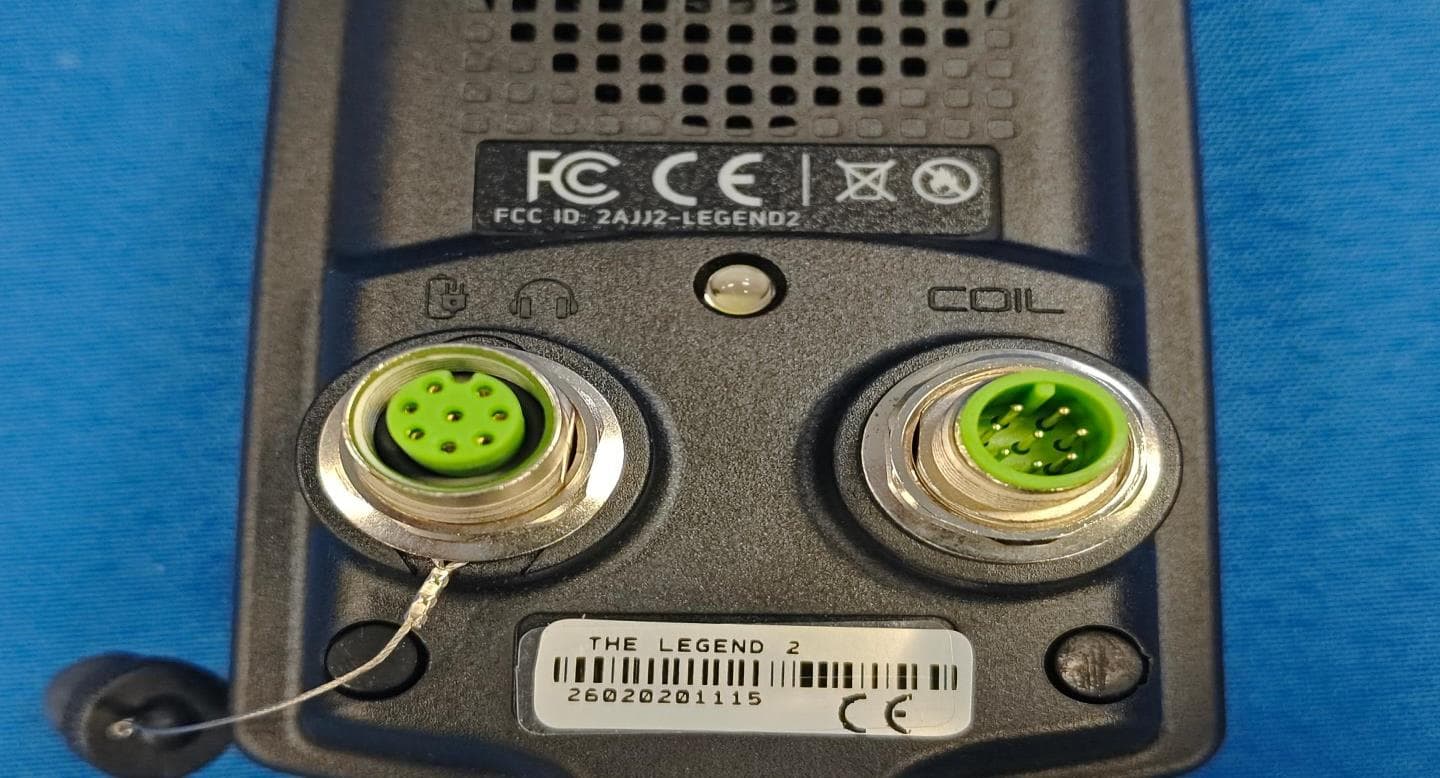
2AJJ2-LEGEND2
May 07, 2026Metal Detector
Equipment Class
DSS - Part 15 Spread Spectrum Transmitter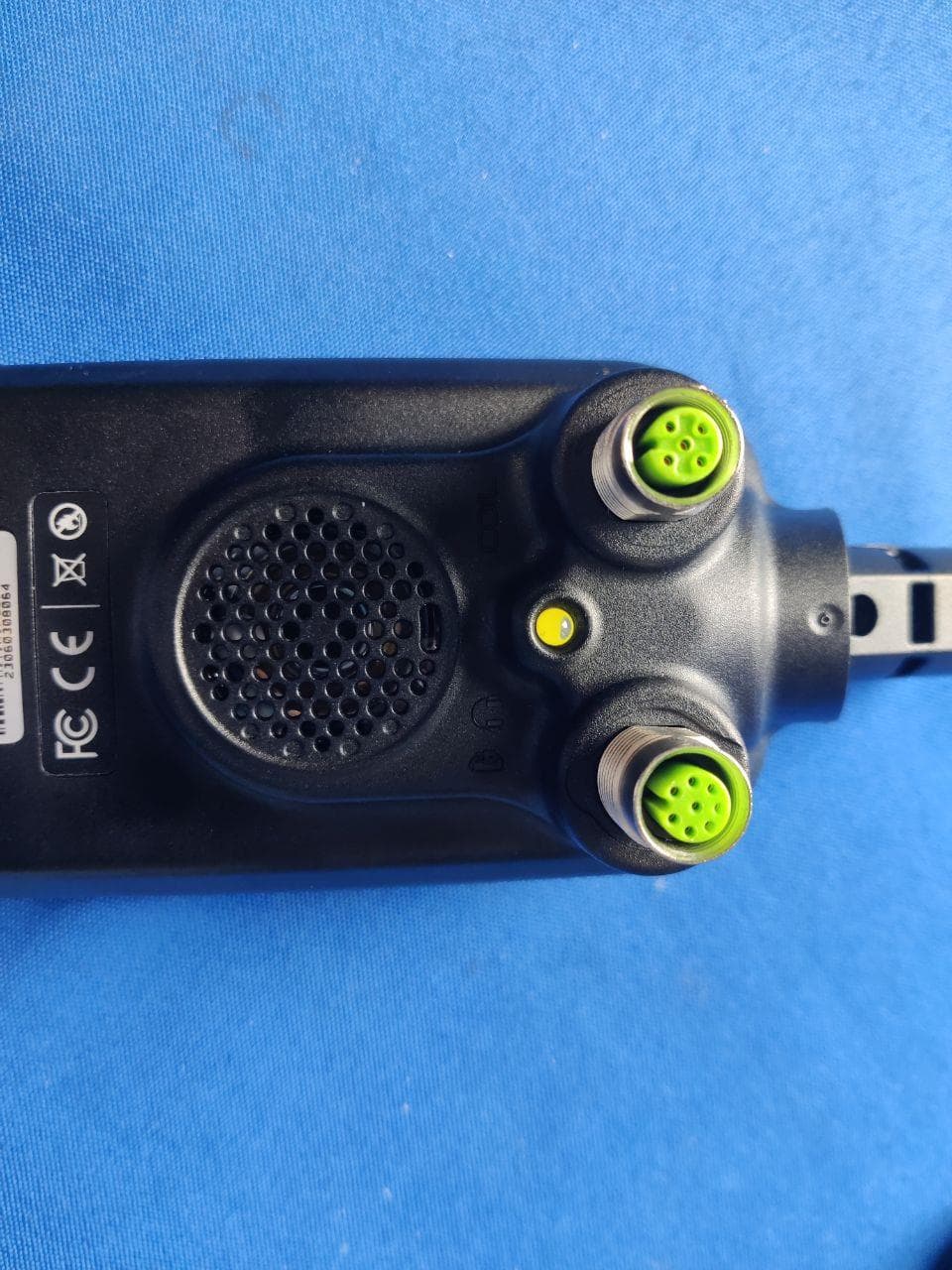
2AJJ2-SIMPLEXNG
Jul 23, 2023METAL DETECTOR
Equipment Class
DSS - Part 15 Spread Spectrum Transmitter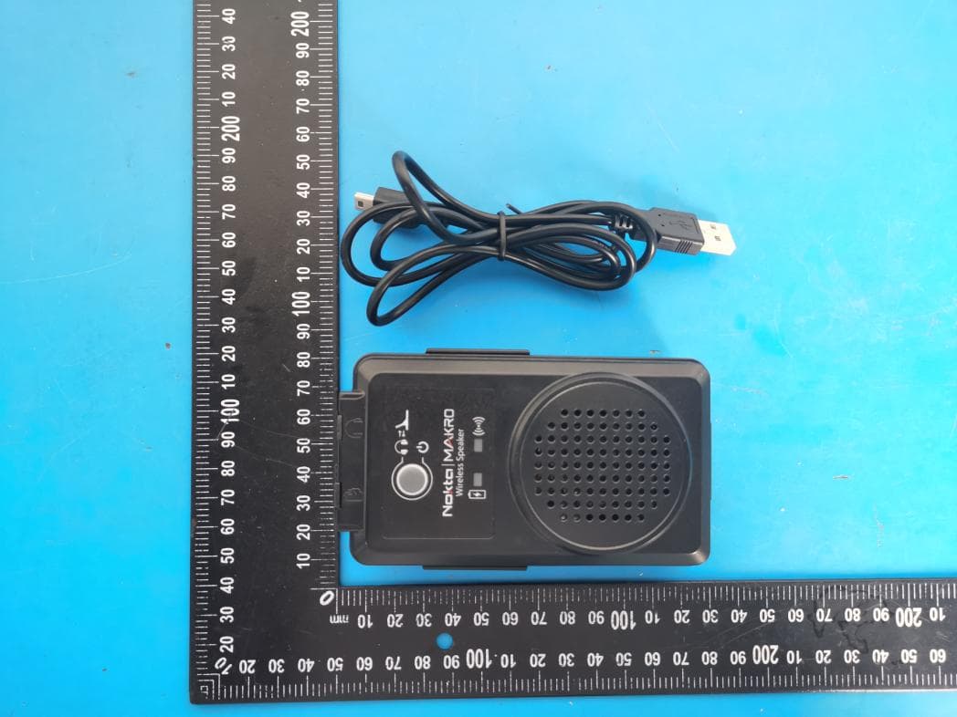
2AJJ2-SPEAKER
Jul 11, 2021WIRELESS LOUDSPEAKER
Equipment Class
JAB - Part 15 Class B Digital Device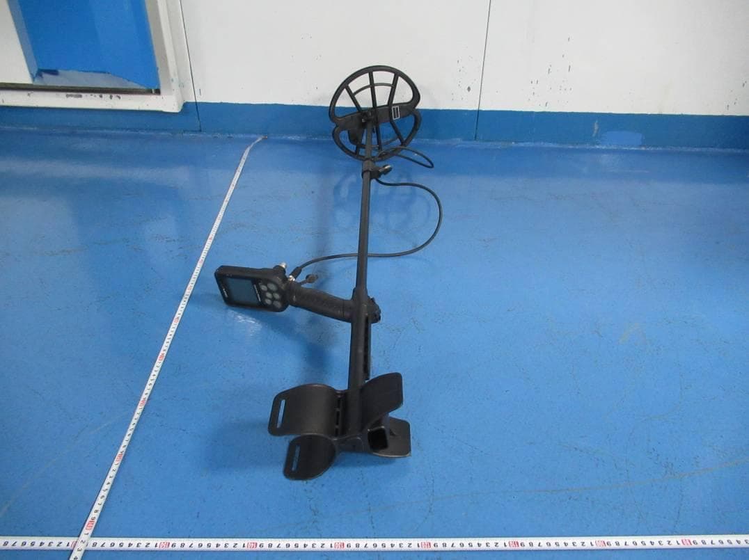
2AJJ2-SIMPLEX
Jan 17, 2020METAL DETECTOR
Equipment Class
DXX - Part 15 Low Power Communication Device Transmitter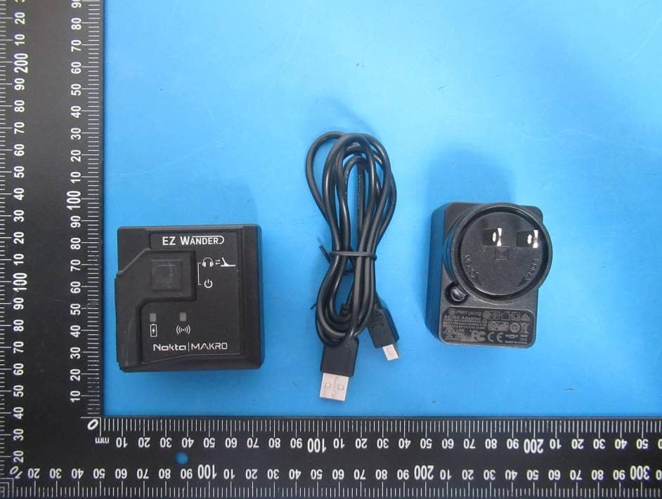
2AJJ2-WANDER
Jan 17, 2020WIRELESS MODULE
Equipment Class
DXX - Part 15 Low Power Communication Device Transmitter