2AJJ2-WANDERWIRELESS MODULE
NOKTA MUHENDISLIK A.S.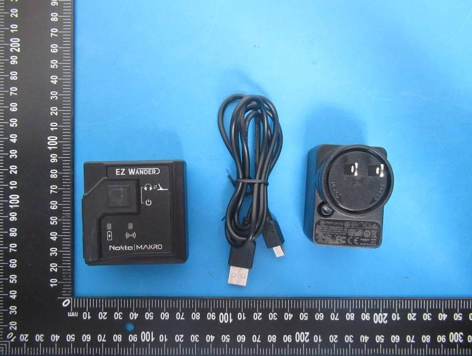
Click to zoom
Application Details
- Equipment Class
- DXX - Part 15 Low Power Communication Device Transmitter
- Date of Grant
- Jan 17, 2020
- Application Purpose
- Original Equipment
- Date of Application
- Jan 17, 2020
- Equipment Note
- WIRELESS MODULE
- Frequency Range
- 2402.00000000 - 2480.00000000
- Company
- NOKTA MUHENDISLIK A.S.
- Country
- Turkey
Documents & Files
Document Text
Text extracted from the exhibit documents filed with the FCC. Open a document above to read the original.
Users Manual
User Guide WIRELESS MODULE 1. MAKE SURE YOUR DETECTOR IS OFF! 2. Insert your wired headphone's plug into the headphone jack located on the side of the EZ Wander. 3. Press and hold down the power button on the EZ Wander for about 7 seconds. The blue LED will flash fast while the button is pressed down. Do not let go of the button until the beep indicating the battery status is heard through the headphones and the red LED on the EZ Wander lights up. Once the button is released, the blue LED will start blinking every 2 seconds. EZ Wander is now ready to be paired. 4. 5Headphones will emit a number of beeps to indicate the battery status as follows: Five (5) beeps for fully charged battery, four (4), three (3), two (2) beeps to indicate diminishing charge and one (1) beep if the battery is low. In addition, the red LED will blink as many times as the beeps (e.g. red LED blinks 5 times with 5 beeps). When the battery is approaching full depletion, the headphones will start emitting continuous beeps at short intervals indicating an immediate need to charge the battery. IMPORTANT! Disconnection and unpairing may occur when the battery is low! 5. Turn the detector on while pressing the SETTINGS button and do NOT let go of the button until ''HP'' is displayed on the screen. 6. When the pairing is successful, the audio will be heard through the headphones and the blue LED on the EZ Wander will start blinking about every second. In addition, the wireless icon will appear at the bottom right corner of the screen. If the pairing is not successful, the wireless icon will start blinking. In such a case, repeat the above steps. 7. Once the pairing is successful, if you experience any distortion in the audio or interference from another detector, first select WIRELESS from options. Change the channel by using the plus (+) and minus (-) button. Each time you press the buttons, channels will change between 00-19-oF. At oF position, the wireless connection is off. When you are not using the EZ Wander, keeping the WIRELESS setting at oF position is recommended. 8. Once the pairing is complete, the EZ Wander and the detector will connect automatically at the next start-up. To turn on or off the EZ Wander, press and hold the power button for about 3 seconds. 9. To adjust the volume, use the VOLUME setting of the detector. IMPORTANT! FOR OPTIMAL PERFORMANCE, BE SURE THAT THE EZ WANDER AND THE DETECTOR ARE ON THE SAME SIDE! Pairing Instructions for Anfibio and Kruzer 1. MAKE SURE YOUR DETECTOR IS OFF! 2. Insert your wired headphone's plug into the headphone jack located on the side of the EZ Wander. 3. Press and hold down the power button on the EZ Wander for about 7 seconds. The blue LED will flash fast while the button is pressed down. Do not let go of the button until the beep indicating the battery status is heard through the headphones and the red LED on the EZ Wander lights up. Once the button is released, the blue LED will start blinking every 2 seconds. EZ Wander is now ready to be paired. 4. Headphones will emit a number of beeps to indicate the battery status as follows: Five (5) beeps for fully charged battery, four (4), three (3), two (2) beeps to indicate diminishing charge and one (1) beep if the battery is low. In addition, the red LED will blink as many times as the beeps (e.g. red LED blinks 5 times with 5 beeps). When the battery is approaching full depletion, the headphones will start emitting continuous beeps at short intervals indicating an immediate need to charge the battery. IMPORTANT! Disconnection and unpairing may occur when the battery is low! 5. Turn the detector on while pressing the ZOOM OUT button and do NOT let go of the button until the blue LED on the EZ Wander starts blinking about every second. 6. When the pairing is successful, the audio will be heard through the headphones. In addition, the headphones icon will appear green on the info bar. If the pairing is not successful repeat the above steps. 7. Once the pairing is successful, if you experience any distortion in the audio or interference from another detector, you can change the wireless headphones channel from the OPTIONS menu. When you are not using the EZ Wander, keeping the wireless headphones connection off is recommended. 8. Once the pairing is complete, the EZ Wander and the detector will connect automatically at the next start-up. To turn on or off the EZ Wander, press and hold the power button for about 3 seconds. 9. To adjust the volume, use the VOLUME setting of the detector. Pairing Instructions for Invenio 1. MAKE SURE YOUR DETECTOR IS OFF! 2. Insert your wired headphone's plug into the headphone jack located on the side of the EZ Wander. 3. Press and hold down the power button on the EZ Wander for about 7 seconds. The blue LED will flash fast while the button is pressed down. Do not let go of the button until the beep indicating the battery status is heard through the headphones and the red LED on the EZ Wander lights up. Once the button is released, the blue LED will start blinking every 2 seconds. EZ Wander is now ready to be paired. 4. Headphones will emit a number of beeps to indicate the battery status as follows: Five (5) beeps for fully charged battery, four (4), three (3), two (2) beeps to indicate diminishing charge and one (1) beep if the battery is low. In addition, the red LED will blink as many times as the beeps (e.g. red LED blinks 5 times with 5 beeps). When the battery is approaching full depletion, the headphones will start emitting continuous beeps at short intervals indicating an immediate need to charge the battery. IMPORTANT! Disconnection and unpairing may occur when the battery is low! 5. Turn the detector on while pressing the sensitivity + button and do NOT let go of the button until the wireless icon (icon) starts blinking at the bottom of the screen. 6. When the pairing is successful, the audio will be heard through the headphones and the blue LED on the EZ Wander will start bli…
Text truncated - open the document above for the full version.
Cover Letter(s)
Date: 2020-01-10 Equipment Autorisation Division Federal Communications Commission 7435 Oakland Mills Road Columbia, MD 21046 FCC ID: 2AJJ2-WANDER Product Name: WIRELESS MODULE Request for Confidentiality Pursuant to Sections 0.457 and 0.459 of the commissions rules, we hereby request that the following documents be held confidential: Schematics Long-term confidential Block diagram Long-term confidential Operation description Long-term confidential These materials contain trade secrets and proprietary information and are not customarily released to the public. The public disclosure of this information might be harmful to the company and provide unjustified benefits to our competitors. Signature: Name DILEK GONULAY Position SALES & MARKETING DIRECTOR Company Name NOKTA MUHENDISLIK A.S. Address EMEK MAH. SAKIZ SOK. NO: 4/1, 34785 SANCAKTEPE, ISTANBUL, TURKEY Tel 902164155686 Fax 902164156343 Email [email protected] NOKTA MUHENDISLIK A.S.
External Photos
PHOTOS OF THE EUT
ID Label/Location Info
30mm 20mm Label Location FCC ID: 2AJJ2-WANDER NOKTA MUHENDISLIK A.S. Model name: WIRELESS MODULE Model No.: EZ WANDER This device complies with Part 15 of the FCC Rules. Operation is subject to the following two conditions: (1) this device may not cause harmful interference, and (2) this device must accept any interference received, including interference that may cause undesired operation.
Internal Photos
Antenna
RF Exposure Info
FCC ID: 2AJJ2- WANDER RF Exposure evaluation According to 447498 D01 General RF Exposure Guidance v06: The 1-g and 10-g SAR test exclusion thresholds for 100 MHz to 6 GHz at test separation distances ≤ 50 mm are determined by: [(max. power of channel, including tune-up tolerance, mW)/(min. test separation distance, mm)] ·[√f(GHz)] ≤ 3.0 for 1-g SAR and ≤ 7.5 for 10-g extremity SAR, where f(GHz) is the RF channel transmit frequency in GHz. Power and distance are rounded to the nearest mW and mm before calculation. The result is rounded to one decimal place for comparison. eirp = p t x g t = (E x d) 2 /30 where: p t = transmitter output power in watts, g t = numeric gain of the transmitting antenna (unitless), E = electric field strength in V/m, --- 10 ((dBuV/m)/20) /10 6 , d = measurement distance in meters (m)--- 3m. So p t = (E x d) 2 /(30 x g t ) Worse case is as below: Field strength = 72.19 dBuV/m @3m (AV) Ant gain 0 dBi; so Ant numeric gain=1 So p t ={[10 (72.19/20) /10 6 x3] 2 /(30x1)}x1000mW =0.005mW So (0.005mW/5mm)x √2.480GHz = 0.002<3.0 for 1-g SAR Then SAR evaluation is not required.
Test Report
FCC TEST REPORT FCC ID: 2AJJ2-WANDER On Behalf of NOKTA MUHENDISLIK A.S. WIRELESS MODULE Model No.: EZ WANDER Prepared for : NOKTA MUHENDISLIK A.S. Address : EMEK MAH. SAKIZ SOK. NO: 4/1, 34785 SANCAKTEPE, ISTANBUL, TURKEY Prepared By : Shenzhen Alpha Product Testing Co., Ltd. Address : Building i, No.2, Lixin Road, Fuyong Street, Bao'an District, 518103, Shenzhen, Guangdong, China Report Number : A1907364-C01-R01 Date of Receipt : November 20, 2019 Date of Test : November 20, 2019-December 18, 2019 Date of Report : December 18, 2019 Version Number : V0 Page 2 of 39 Report No.: A1907364-C01-R01 TABLE OF CONTENTS Description Page 1. Summary of Standards And Results ................................................................................. 6 1.1. Description of Standards and Results ......................................................................... 6 2. General Information ........................................................................................................... 7 2.1. Description of Device (EUT) ...................................................................................... 7 2.2. Accessories of Device (EUT) ..................................................................................... 8 2.3. Tested Supporting System Details .............................................................................. 8 2.4. Block Diagram of connection between EUT and simulators ...................................... 8 2.5. Test Mode Description ................................................................................................ 8 2.6. Test Conditions ........................................................................................................... 9 2.7. Test Facility ................................................................................................................ 9 2.8. Measurement Uncertainty ........................................................................................... 9 2.9. Test Equipment List .................................................................................................. 10 3. Power Line Conducted Emission Test ............................................................................. 11 3.1. Block Diagram of Test Setup .................................................................................... 11 3.2. Test Limits ................................................................................................................ 11 3.3. Configuration of EUT on Test .................................................................................. 11 3.4. Operating Condition of EUT .................................................................................... 11 3.5. Test Procedure .......................................................................................................... 12 3.6. Test Results ............................................................................................................... 12 4. Radiated Emission Test ..................................................................................................... 14 4.1. Block Diagram of Test Setup .................................................................................... 14 4.2. Test Limit .................................................................................................................. 15 4.3. Configuration of EUT on Test .................................................................................. 16 4.4. Operating Condition of EUT .................................................................................... 16 4.5. Test Procedure .......................................................................................................... 16 4.6. Test Results ............................................................................................................... 17 5. Band Edge Test .................................................................................................................. 22 5.1. Block Diagram of Test Setup .................................................................................... 22 5.2. Test Limit .................................................................................................................. 22 5.3. Configuration of EUT on Test .................................................................................. 23 5.4. Operating Condition of EUT .................................................................................... 23 5.5. Test Procedure .......................................................................................................... 23 5.6. Test Results ............................................................................................................... 25 6. Occupied bandwidth Test ................................................................................................. 27 6.1. Block Diagram of Test Setup .................................................................................... 27 6.2. Test Limit .................................................................................................................. 27 6.3. Test Procedure .......................................................................................................... 27 6.4. Test Results ............................................................................................................... 27 7. Antenna Requirement ....................................................................................................... 31 7.1. Standard Requirement ............................................................................................... 31 Page 3 of 39 Report No.: A1907364-C01-R01 7.2. Antenna Connected Construction ............................................................................. 31 7.3. Results ....................................................................................................................... 31 8. Photograph ...................…
Text truncated - open the document above for the full version.
Test Setup Photos
Photos of Radiated Emission Test Conducted Emission
Contact Information
Applicant
DILEK Gonulay(SALES & MARKETING DIRECTOR)
Test Firm
Shenzhen Alpha Product Testing Co., LTD.Simple Guan
[email protected]+86 755 29766001-810
Technical Specifications
| # | Rule Parts | Frequency Range | Power Output |
|---|---|---|---|
| 1 | 15C | 2.40 GHz - 2.48 GHz | - |
Other Applications from NOKTA MUHENDISLIK A.S.
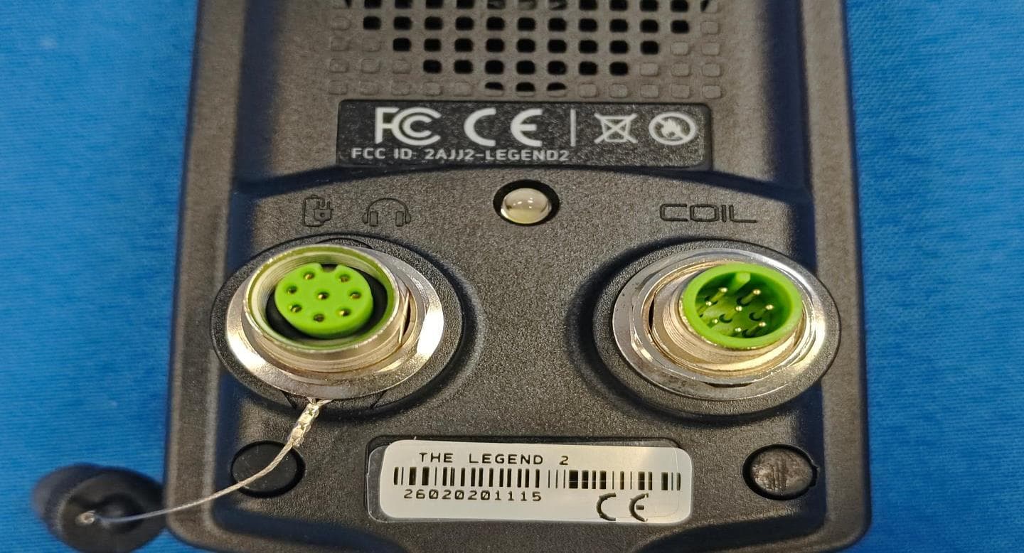
2AJJ2-LEGEND2
May 07, 2026Metal Detector
Equipment Class
DSS - Part 15 Spread Spectrum Transmitter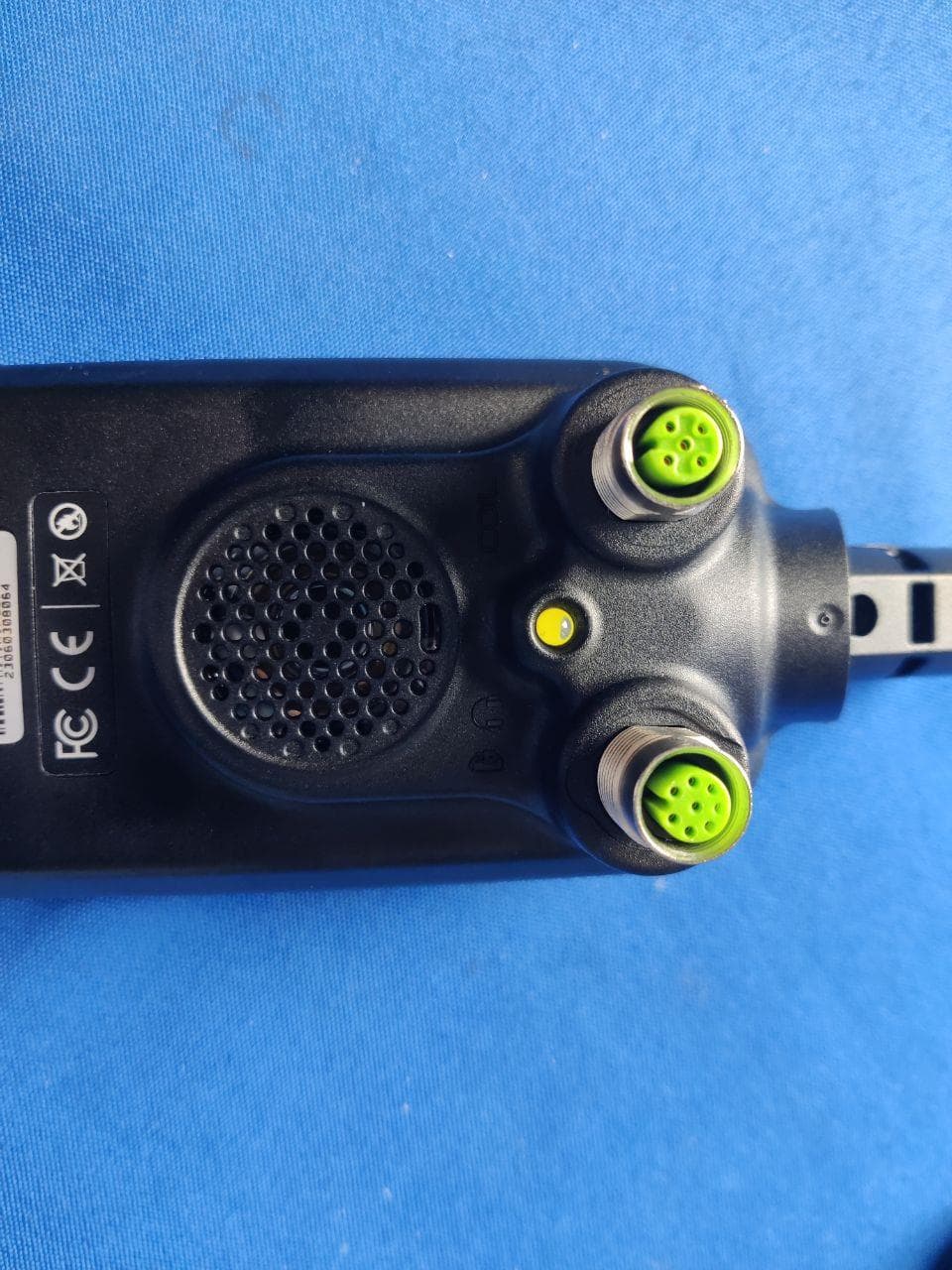
2AJJ2-SIMPLEXNG
Jul 23, 2023METAL DETECTOR
Equipment Class
DSS - Part 15 Spread Spectrum Transmitter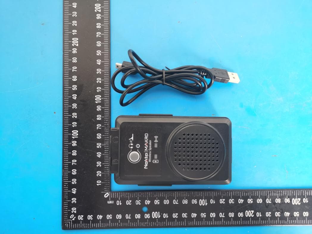
2AJJ2-SPEAKER
Jul 11, 2021WIRELESS LOUDSPEAKER
Equipment Class
JAB - Part 15 Class B Digital Device
2AJJ2-DETECTOR
Jul 09, 2021METAL DETECTOR
Equipment Class
DXX - Part 15 Low Power Communication Device Transmitter
2AJJ2-SIMPLEX
Jan 17, 2020METAL DETECTOR
Equipment Class
DXX - Part 15 Low Power Communication Device Transmitter