2AJJ2-LEGEND2Metal Detector
NOKTA MUHENDISLIK A.S.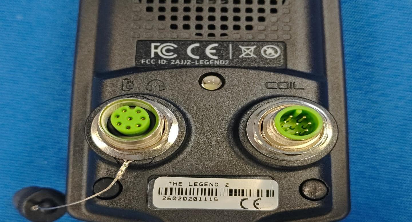
Click to zoom
Application Details
- Equipment Class
- DSS - Part 15 Spread Spectrum Transmitter
- Date of Grant
- May 07, 2026
- Application Purpose
- Original Equipment
- Equipment Note
- Metal Detector
- Frequency Range
- 2402.00000000 - 2480.00000000
- Company
- NOKTA MUHENDISLIK A.S.
- Country
- Turkey
Documents & Files
Document Text
Text extracted from the exhibit documents filed with the FCC. Open a document above to read the original.
Users Manual
1 USER MANUAL High-Performance Metal Detector! READ CAREFULLY BEFORE OPERATION OF THE DEVICE! LEGAL DISCLAIMERS Comply with applicable laws and regulations governing use of metal detectors while using this detector. Do not use the detector without authorization in protected or archeological sites. Do not use this detector around unexploded ordnance or in restricted military zones without authorization. Notify appropriate authorities with details of any historical or culturally signi cant artifacts you nd. WARNINGS The LEGEND 2 is a state-of-the-art electronic device. Do not assemble or operate the device before reading the user manual. Do not store the device and search coil under extremely low or high temperatures for extended periods. (Storage Temperature: - 20°C to +45°C / - 4°F to +113°F) The device features an IP68 waterproof rating, allowing submersion up to 5 meters (16 ft), excluding the Bluetooth® headphones. Pay attention to the items below after using the device especially under salty water: 1. Rinse the system box, shaft, and coil with tap water, making sure all saltwater is fully removed from the connectors. 2. Do not use any chemicals for cleaning and/or for any other purposes. 3. Wipe the screen and the shaft dry with a soft, non-scratch cloth. Protect the detector from impact during use. When shipping, place it in the original carton and secure it with shock-resistant packaging. The LEGEND 2 metal detector may only be disassembled and repaired by Nokta Authorized Service Centers. Unauthorized disassembly/intrusion into the metal detector control housing for any reason voids the warranty. IMPORTANT! Do not use the device indoors, where surrounding metals may cause continuous target signals. Use only in open outdoor areas. Keep other detectors and electromagnetic devices a minimum of 10 m (30 ft) from the device. Do not carry any metal objects while using the device. Keep the device away from your shoes while walking. Metal on your body or inside your shoes may be detected as targets. ASSEMBLY INTRODUCTION TO THE DEVICE DISPLAY BATTERY INFORMATION CORRECT USE QUICK GUIDE COMMON AND MODE-BASED SETTINGS SEARCH MODES USER PROFILE MUTE FUNCTION TARGET ID GROUND BALANCE PINPOINT FERROCHECK™ MINERALIZATION INDICATOR TARGET DEPTH QUICK SETTINGS 1. Sensitivity 2. Frequency 3. Discrimination Patterns 4. Recovery Speed 5. Bottle Cap Rejection 5.1 Iron Rejection in Relic Mode 6. Iron Filter 7. Stability in Beach Mode CONTENTS : 3-6 : 7 : 8 : 9 : 10 : 11 : 11-12 : 12-14 : 14-15 : 15 : 16 : 16-18 : 18 : 19 : 20 : 20 : 20-25 : 21 : 22 : 23 : 24 : 24 : 24 : 25 : 25 1 SETTINGS 1. Volume Level 2. Frequency Shift 3. Ground Suppressor 4. Deep Target Identi cation 5. Notch (Accepting and Rejecting IDs) 6. Screen and Keypad Backlight 7. Vibration 8. LED Flashlight AUDIO OPTIONS 1. Speaker 2. Bone Conduction Headphones 3. Bluetooth® Headphones 4. Multiple Audio Output 5. Wired Headphones SUB-SETTINGS 1. Number of Tones 2. Tone Volume 3. Tone Frequency 4. Tone Break 5. Threshold Level 6. Threshold Frequency 7. Audio Gain 8. Clock and Usage Duration 9. FerroCheck™ / Mineralization Option WARNING MESSAGES REVERTING BACK TO FACTORY DEFAULTS SOFTWARE UPDATE HEADPHONES TECHNICAL SPECIFICATIONS RECOMMENDED ACCESSORIES : 25-30 : 26 : 26-27 : 27 : 27 : 28-29 : 29 : 30 : 30 : 30-31 : 31 : 31 : 31 : 31 : 31 : 32-40 : 32-33 : 34 : 35-36 : 36-37 : 38 : 39 : 39 : 40 : 40 : 41 : 41 : 41 : 41 : 42 : 43 CONTENTS (Continued) 2 ASSEMBLY After inserting the washers onto the lower shaft, attach the lower shaft to the search coil and secure it by tightening the screw. Do not overtighten. Open the lever latches to connect the middle shaft to the upper and lower shafts. Adjust the length to your height, tighten the side screws, and close the latches to secure. IMPORTANT! During assembly, make sure that the red lines on the shafts are aligned to overlap, as shown in below. 3 Wind the search coil cable around the shaft without overstretching (Figure A), then plug the connector into the search coil input socket on the system box (Figure B) and secure it by tightening the nut until you hear clicks. Figure B: If you want to adjust the armrest, open the latch. Once it reaches your desired height, close the latch to secure it. (Figure C) Figure C: Attach the armrest strap as shown in the picture (Figure D) and tighten it according to the width of your arm. Figure D: 4 Figure A 1 IMPORTANT! When the red lines on the shafts are aligned and the shafts are set to their shortest position, the search coil becomes rotatable. By rotating and folding the search coil, you can place the detector in a compact carrying position. IMPORTANT! To prepare the detector for use from the compact position, the system box and the search coil must be aligned in the same direction, and the red lines on the shafts must be fully aligned. Otherwise, the shafts cannot be extended. 5 6 IMPORTANT! The at section on the rear of the detector shafts ensures a tight t. IMPORTANT! The red lines on the rear of the shafts indicate the maximum length to which the shafts can be extended. Do not exceed this limit. INTRODUCTION TO THE DEVICE 1. LCD Screen 2. Power / Settings Button Press and hold the Power / Settings button for 2 seconds to turn the device on. Press once to enter or exit settings. To turn the device o , press and hold the Power / Settings button. Note : While in settings, pressing and holding the Power / Settings button will not turn the device o . 3. Ground Balance Button Press the Ground Balance button once to enter or exit the ground balance menu. Press and hold the Ground Balance button to perform automatic ground balancing. 4. Right Button On the main screen, the Right button navigates between modes, while in the settings menu, it navigates through the settings options. 5. Up and Down Buttons Use the Up and Down buttons to adjust the selected quick setting on the main screen or to change any setting value in the settings menu. 6. Left Button …
Text truncated - open the document above for the full version.
Users Manual
3. Start pumping the search coil up and down from about 15-20 cm (~6’’- 8’’) above the ground down to 3 cm (~1’’) o the ground with smooth movements and keeping it parallel to the ground. 4. Continue until the audio reduces in response to the ground. Based on ground conditions, it usually takes about 2-4 pumps for the ground balance to be completed. 5. The ground balance value is displayed on the screen in the ID area and in the Info Bar. In order to ensure that the ground balance is proper, ground balance at least 2-3 times and check the ground balance values on the display. In general, the di erence between the values shall not be higher than 1-2 numbers. 6. If you cannot ground balance, it means that either the ground is too conductive or not mineralized or there is a target right below the search coil. In such a case, retry ground balancing at a di erent spot. Manual Ground Balance Allows you to manually modify the ground balance value. It is not preferred mostly because it takes time. However, it is the preferred option in cases where a successful ground balance cannot be performed using other methods or minor corrections are required to the automatic balance. 1. Find a clear spot without metals. 2. Press the Ground Balance button once. The device will switch to the ground balance screen. The current ground balance value is displayed in the center of the screen. If ground balance has not been performed previously, this value will always be zero (0). Press once 3. You need to listen to the sounds coming from the ground in order to perform manual ground balance. Pump the search coil up and down from about 15-20 cm (~6’’- 8’’) above the ground down to 3 cm (~1’’) o the ground with smooth movements and keeping it parallel to the ground. 4. If you are getting a low tone while pumping the coil, it means that that you should increase the ground balance value using the Up button. On the other hand, if you are getting a high tone, you should decrease the ground balance value using the Down button. 5. Continue the above process until the ground response is eliminated. 6. Press the Ground Balance button once to exit. The ground balance value may vary in single frequencies and Multi frequency in certain soil types. The sound may not be eliminated completely on certain terrains. In this case, if the ground noise is minimized, it means that the ground balance has been done. Ground Tracking The device tracks the changes in the ground during detection and updates the ground balance automatically. Ground changes that are not visible to the eye will a ect the depth and discrimination performance of the detector. 1. To activate ground tracking, press the Ground Balance button once. The device will go into the ground balance screen. 2. Press the Pinpoint & Accept/Reject button once. In the Info Bar, next to the ground balance icon, ground tracking icon will appear. Press once Ground tracking is now active. Press the Ground Balance button once to go back to the main screen. When the Ground Tracking feature is activated, the ground balance icon and the numerical values indicating the ground balance level are removed from the information area. The Ground Tracking icon is displayed, and in the section showing real-time ground measurements, the ground balance level calculated by the Ground Tracking feature and at which the device is operating is shown. The device updates the ground balance automatically as long as the search coil is swung over the ground. Tracking is suitable for use in areas where di erent soil structures are present within the same land or in elds where mineralized rocks are scattered widely apart. If you use ground tracking in areas where hot rocks are intensely present, the device may not be able to eliminate these highly mineralized rocks or you may miss the smaller or deeper metals. When the Tracking feature is activated, the ground balance level ashes on the screen. In Relic mode, when the Ground Balance 2 is activated while the tracking feature is on, the ground balance level will be shown steady to avoid confusion. 17 Second Ground Balance Feature in Relic Mode Due to its con guration, Relic mode may cause the device to give false signals to ground changes and mineralized/hot rocks. This may cause discomfort to the user during detection. Relic mode o ers users a 2nd Ground Balance feature to overcome mineralized/hot rocks, red bricks and other ground changes in the surrounding environment that have di erent properties than the soil that’s been ground balanced. With the second ground balance, depending on the properties of the hot rock or brick, in some cases, complete silence can be achieved over these falsing targets. In other cases, a broken signal may be heard. Broken sounds indicate that the detected target is a mineralized/hot rock. To use this feature: 1. Press the Ground Balance button to access the setting. 2. Activate the 2nd Ground Balance feature by pressing the Quick Settings button. When the 2nd Ground Balance is activated, the number “2” appears on the screen above the letters Gb. 3. You can perform the 2nd Ground Balance by pressing and holding the Pinpoint & Accept/Reject button. When Relic mode is selected, 1st and 2nd Ground Balancing can only be performed automatically. Manual ground balancing is not possible. 4. You can switch back from the 2nd Ground Balance to the 1st Ground Balance by pressing the Quick Settings button again. Resetting the 1st and 2nd Ground Balance Settings in the Relic Mode While Relic mode is selected, the Ground Balance value is reset by entering the ground balance menu and long pressing the Up button. When the button is held down, the animation is shown on the screen. To reset the 2nd Ground Balance value, rst activate the 2nd Ground Balance. Reset the 2nd Ground Balance value by pressing the Up button again. PINPOINT Pinpoint is to nd the center or the exact location of a detected target. The LEGEND 2 is a motion detector. In othe…
Text truncated - open the document above for the full version.
Users Manual
In the ID Enable / Disable setting, pressing the “Ground Balance” button automatically lowers the Sensitivity level. The letters “LS” are displayed on the screen. LS: Low Sensitivity Press once When both the “Automatic Sensitivity Reduction” and “Sequential ID Enable / Disable” features are activated, the screen appears as shown below: Press once The LEGEND 2 does not produce a sound for rejected targets, but it displays their ID values on the screen in the Notch (Accepting and Rejecting IDs) setting. When you re-enter the Notch (Accepting and Rejecting IDs) setting, the cursor and Target ID remain in their last position. You can press the Power / Settings button to exit the menu. IMPORTANT! When you exit the Notch (Accepting and Rejecting IDs) setting, the currently selected Discrimination Pattern remains active. If you want to switch to the “C” Custom Discrimination Pattern, you can change the Discrimination Pattern from the quick settings. 6. Screen and Keypad Backlight It enables you to adjust the display backlight level according to your personal preference. It ranges from 0 to 5 and A1 to A5. At 0 level, the backlight is o . At 1-5 levels, it will be continuously lit. At A1-A5 levels, it lights up only for a short period of time when a target is detected or while navigating the menu and then it goes o . ParkField Beach Relic Gold This setting is common to all modes; changes will take e ect in all modes. Adjusting the Keypad Backlight When the Screen Backlight setting is selected, you can turn the keypad backlight on or o by pressing the Pinpoint & Acept/ Reject button. The continuous operation of the backlight will a ect power consumption, which is not recommended. The backlight setting is restored to the nal saved setting when the device is turned o and on again. Adjusting the Backlight 1. Press the Power / Settings button once, and use the Right and Left buttons to select the Screen Backlight setting. 2. Change the backlight level using the Up and Down buttons. 3. Press the Power / Settings button once to go back to the main screen. When the backlight is on, the backlight icon will be displayed in the Info Bar at the top of the screen. 29 7. Vibration This feature provides feedback to the user by producing a vibration e ect when a target is detected. It can be used independently or together with the audio response. When audio response is disabled, all responses during target detection are provided to the user as vibration only. The Vibration setting can be set to 0 (O ) or 1 (On). At 0 vibration is o . The magnitude of the vibration e ect can vary according to the depth of the target and the swinging speed. ParkField Beach Relic Gold This setting is common to all modes; changes will take e ect in all modes. When you turn o and on the device, it will start with the last vibration level you chose. Adjusting the Vibration 1. Press the Power / Settings button once. Select vibration using the Right and Left buttons. The current value will be displayed on screen. 2. Change the level using the Up and Down buttons. 3. Press the Power / Settings button once to go back to the main screen. When the vibration is on, the vibration icon will be displayed in the Info Bar at the top of the screen. Even if the vibration is on, it will not generate a response for targets while in the settings menu but only in the detection screen. 8. LED Flashlight Use this setting to operate a headlight that illuminates the search area during night or low-light conditions. LED Flashlight does not operate when the device is o . It is recommended to turn it on only when necessary since its operation consumes extra battery power. LED Flashlight setting can be set to 0 (o ) or to 1 (on). The LED Flashlight will be o at each start up. Turning the LED Flashlight On/O 1. Press the Power / Settings button once. Select LED Flashlight using the Right and Left buttons. The current value will be displayed on screen: 0 (O ) or 1 (On). 2. Turn the ashlight On/O using the Up and Down buttons. 3. Press the Power / Settings button once to go back to the main screen. When the LED Flashlight is on, the ashlight icon will be displayed in the Info Bar at the top of the screen. AUDIO OPTIONS This setting is used to select the audio output. To select the audio output, choose the Audio Options setting from the Settings menu. When this setting is selected, three di erent audio output options are displayed on the screen. You can change the audio output option using the Up and Down buttons. The default audio output is the speaker. 30 1. Speaker When the speaker icon in the sound options settings is selected, the sound is emitted through the device’s speaker. 2. Bone Conduction Headphones When the bone conduction headphones icon in the sound options settings is selected, the sound is emitted through the bone conduction headphones. IMPORTANT! When the bone conduction headphone audio output is selected, make sure that the bone conduction headphones are connected. If the bone conduction headphones are not connected, you will not receive any audio output from the detector. 3. Bluetooth® Headphones When the Bluetooth® icon in the sound options settings is selected, The LEGEND 2 turns on Bluetooth® and enters pairing mode. In pairing mode, the Bluetooth® icon blinks. The device will search for the headphones it has been paired with initially and try to connect to those. This will prevent the device from connecting to other Bluetooth® devices when the Bluetooth® setting is on. If you want to pair the device with di erent Bluetooth® headphones (other than those it was initially paired with) you must delete them from memory. Once it pairs with any Bluetooth® headphones (Nokta BT Headphones or others), one of the icons below will be displayed in the Info Bar: When headphones are connected, they will automatically turn o if no sound is transmitted from the device for 14 minutes. Standard Bluetooth® headphones connected. aptX™ Low Latency hea…
Text truncated - open the document above for the full version.
Attestation Statements
NOKTA MUHENDISLIK A.S. * the applicant must designate a contact located in the United States for purposes of acting as the applicant’s agent for service of process, regardless of whether the applicant is a domestic or foreign entity. An applicant located in the United States may designate itself as the agent for service of process. U.S. Agent Designation for Service of Process - Certification Attestation Letter DATE 2026/4/2 ATTN.: Reviewing Engineer FCC ID: 2AJJ2-LEGEND2 FRN: 0025825795 Per section 2.911(d)(7) of the FCC rules, NOKTA MUHENDISLIK A.S. certifies that the equipment for which authorization is sought is designated to the following U.S. agent* for service of process: Company Name: NOKTA ENGINEERING INC. FRN: 0034007773 Physical U.S. Company Address: 6500 Iron Horse Blvd, North Richland Hills, TX 76180 Agent name: MARK TYMENSKY Agent Email Address: [email protected] Tel: +1 817 498 7100 The above contact person accepts the obligation for service of process. The applicant accepts to maintain an agent for no less than one year after the grantee has terminated all marketing and importation or the conclusion of any Commission-related proceeding involving the equipment. Applicant Signed: Signed: Printed name: DILEK GONULAY Title: SALES & MARKETING DIRECTOR Company Name: NOKTA MUHENDISLIK A.S. Date: 4/22/2026 Agent Signed (if different to Applicant): Signed: Printed name: MARK TYMENSKY Title: Manger Company Name: NOKTA ENGINEERING INC.. Date: 4/22/2026
Attestation Statements
NOKTA MUHENDISLIK A.S. (April 22, 2026) Eurofins Electrical and Electronic Testing NA, Inc. 914 West Patapsco Avenue Baltimore, MD 21230 ATTN.: Reviewing Engineer FCC ID: 2AJJ2-LEGEND2 NOKTA MUHENDISLIK A.S. certifies that the equipment for which authorization is sought is not “covered” equipment prohibited from receiving an equipment authorization pursuant to section 2.903 of the FCC rules. Note: If the equipment for which the applicant seeks authorization is produced by any of the entities identified on the current Covered List, the applicant should include an explanation on why the equipment is not “covered” equipment. NOKTA MUHENDISLIK A.S. certifies that, as of the date of the filing of the application, the applicant is not identified on the Covered List as an entity producing “covered” equipment. Sincerely, Signature: Name DILEK Gonulay Position SALES & MARKETING DIRECTOR Company Name NOKTA MUHENDISLIK A.S. Address Melek Aras Blv. No:1, 34953, Aydınlı, KOSB, Tuzla, Istanbul, Turkey Tel 902164155686 Fax 902164156343 Email [email protected]
Attestation Statements
(NOKTA MUHENDISLIK A.S.) (April 22, 2026) Eurofins Electrical and Electronic Testing NA, Inc. 914 West Patapsco Avenue Baltimore, MD 21230 RE: Attestation Statements Part 2.911(d)(5)(i) request for (FCC ID: 2AJJ2-LEGEND2) [NOKTA MUHENDISLIK A.S.] (“the applicant”) certifies that the equipment for which authorization is sought is not “covered” equipment prohibited from receiving an equipment authorization pursuant to section 2.903 of the FCC rules. We also certify that, as of the date of the filing of the application, the equipment does not utilize cyber-security or anti-virus software from Kaspersky Lab, Inc, or any of its successors and assignees, which is also on the “covered list”. Sincerely, () (DILEK Gonulay) (NOKTA MUHENDISLIK A.S.) (April 22, 2026) Eurofins Electrical and Electronic Testing NA, Inc. 914 West Patapsco Avenue Baltimore, MD 21230 RE: Attestation Statements Part 2.911(d)(5)(ii) request for (FCC ID: 2AJJ2-LEGEND2) [NOKTA MUHENDISLIK A.S.] (“the applicant”) certifies that, as of the date of the filing of the application, the applicant is not identified on the Covered List as an entity producing “covered” equipment. Sincerely, () (DILEK Gonulay)
Cover Letter(s)
NOKTA MUHENDISLIK A.S. (April 22, 2026) Eurofins Electrical and Electronic Testing NA, Inc. 914 West Patapsco Avenue Baltimore, MD 21230 RE: CONFIDENTIALITY REQUEST FOR (Metal Detector / The Legend 2, Legend 2 Pro Pack, Legend 2 Starter Pack # FCC ID: 2AJJ2-LEGEND2#) To Whom It May Concern: This letter serves as an official request for confidentiality under sections 0.457 and 0.459 of CFR 47. We have requested that the (Schematics, Block diagram, Operation description) required to be submitted with this application be permanently withheld from public review. These materials contain trade secrets and proprietary information and are not customarily released to the public. The public disclosure of this information might be harmful to the company and provide unjustified benefits to our competitors. Please contact me if there is any information you may need. Sincerely, Signature: Name DILEK Gonulay Position SALES & MARKETING DIRECTOR Company Name NOKTA MUHENDISLIK A.S. Address Melek Aras Blv. No:1, 34953, Aydınlı, KOSB, Tuzla, Istanbul, Turkey Tel 902164155686 Fax 902164156343 Email [email protected]
Cover Letter(s)
NOKTA MUHENDISLIK A.S. (April 22, 2026) Eurofins Electrical and Electronic Testing NA, Inc. 914 West Patapsco Avenue Baltimore, MD 21230 RE: LETTER OF AGENT AUTHORIZATION To Whom It May Concern: We, the undersigned, hereby authorize (Shenzhen NCT Testing Technology Co., Ltd.) to act on our behalf in all matters relating to application for equipment authorization, including the signing of all documents relating to these matters. We also hereby certify that no party to the application authorized hereunder is subject to the denial of benefits, including FCC benefits, pursuant to Section 5301 of the Anti-Drug Abuse Act of 1988, 21 U.S.C.853(a). This agreement expires one year from the current date. Sincerely, Signature: Name DILEK Gonulay Position SALES & MARKETING DIRECTOR Company Name NOKTA MUHENDISLIK A.S. Address Melek Aras Blv. No:1, 34953, Aydınlı, KOSB, Tuzla, Istanbul, Turkey Tel 902164155686 Fax 902164156343 Email [email protected]
External Photos
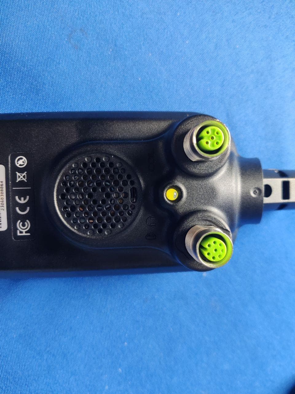
FCC ID: 2AJJ2-LEGEND2 FCC ID: 2AJJ2-LEGEND2 FCC ID: 2AJJ2-LEGEND2 FCC ID: 2AJJ2-LEGEND2 FCC ID: 2AJJ2-LEGEND2
ID Label/Location Info
4.5cm 0.5cm Label location FCC ID: 2AJJ2-LEGEND2
Internal Photos
FCC ID: 2AJJ2-LEGEND2 FCC ID: 2AJJ2-LEGEND2 FCC ID: 2AJJ2-LEGEND2 FCC ID: 2AJJ2-LEGEND2 FCC ID: 2AJJ2-LEGEND2 FCC ID: 2AJJ2-LEGEND2 FCC ID: 2AJJ2-LEGEND2 FCC ID: 2AJJ2-LEGEND2 BT ANT FCC ID: 2AJJ2-LEGEND2 FCC ID: 2AJJ2-LEGEND2 FCC ID: 2AJJ2-LEGEND2 FCC ID: 2AJJ2-LEGEND2 FCC ID: 2AJJ2-LEGEND2
RF Exposure Info
RF Exposure evaluation According to 447498 D04 Interim General RF Exposure Guidance v01 1-mW Test Exemption A single RF source is exempt RF device (from the requirement to show data demonstrating compliance to RF exposure limits, as previously mentioned) if the available maximum time-averaged power is no more than 1 mW, regardless of separation distance. This exemption applies to all operating configurations and exposure conditions, for the frequency range 100 kHz to 100 GHz, regardless of fixed, mobile, or portable device exposure conditions. This is a standalone exemption, and it cannot be applied in conjunction with any other test exemption. 1-mW Test Exemption for Multiple Sources The 1-mW exemption intended for single transmitters may be also applied to simultaneous transmission conditions, within the same host device, according one of the following criteria: a) When maximum available power each individual transmitting antenna within the same time averaging period is ≤ 1 mW, and the nearest parts of the antenna structures of the simultaneously operating transmitters are separated by at least 2 cm. b) When the aggregate maximum available power of all transmitting antennas is ≤ 1 mW in the same time-averaging period. This exemption may not be combined with any other exemption. SAR-Based Exemption This exemption is applicable to the frequency range between 300 MHz and 6 GHz, with test separation distances between 0.5 cm and 40 cm, and for all RF sources in fixed, mobile, and portable device exposure conditions. Accordingly, a RF source is considered an RF exempt device if its available maximum time-averaged (matched conducted) power or its effective radiated power (ERP), whichever is greater, are below a specified threshold. This exemption threshold was derived based on general population 1-g SAR requirements. This method shall only be used at separation distances from 0.5 cm to 40 cm and at frequencies from 0.3 GHz to 6 GHz (inclusive). Pth is given by follow Formulas “f” is in GHz, “d” is the separation distance (cm) Simultaneous Transmission with SAR-based Exemptions For these cases, a device with multiple RF sources transmitting simultaneously will be considered an RF exempt device if the condition of following Formula is satisfied. (1-mW Test Exemption) As this equipment: Pt = 10 (Pm/10) where: Pt = transmitter output power in milliwatts, Pm = measured transmitter output power in dBm, So Pt =10 (-0.102/10) mW =0.9768 mW<1mW Then the SAR test is exempted.
Test Report
1 / 44 Dwell Time Condition Mode Frequency (MHz) Antenna Pulse Time (ms) Total Dwell Time (ms) Burst Count Period Time (ms) Limit (ms) Verdict NVNT 1-DH1 2441 Ant1 0.376 118.816 316 31600 400 Pass NVNT 1-DH3 2441 Ant1 1.632 264.384 162 31600 400 Pass NVNT 1-DH5 2441 Ant1 2.88 285.12 99 31600 400 Pass NVNT 2-DH1 2441 Ant1 0.386 123.134 319 31600 400 Pass NVNT 2-DH3 2441 Ant1 1.638 250.614 153 31600 400 Pass NVNT 2-DH5 2441 Ant1 2.886 326.118 113 31600 400 Pass NVNT 3-DH1 2441 Ant1 0.387 123.453 319 31600 400 Pass NVNT 3-DH3 2441 Ant1 1.637 266.831 163 31600 400 Pass NVNT 3-DH5 2441 Ant1 2.887 311.796 108 31600 400 Pass Dwell NVNT 1-DH1 2441MHz Ant1 One Burst Dwell NVNT 1-DH1 2441MHz Ant1 Accumulated 2 / 44 Dwell NVNT 1-DH3 2441MHz Ant1 One Burst Dwell NVNT 1-DH3 2441MHz Ant1 Accumulated 3 / 44 Dwell NVNT 1-DH5 2441MHz Ant1 One Burst Dwell NVNT 1-DH5 2441MHz Ant1 Accumulated 4 / 44 Dwell NVNT 2-DH1 2441MHz Ant1 One Burst Dwell NVNT 2-DH1 2441MHz Ant1 Accumulated 5 / 44 Dwell NVNT 2-DH3 2441MHz Ant1 One Burst Dwell NVNT 2-DH3 2441MHz Ant1 Accumulated 6 / 44 Dwell NVNT 2-DH5 2441MHz Ant1 One Burst Dwell NVNT 2-DH5 2441MHz Ant1 Accumulated 7 / 44 Dwell NVNT 3-DH1 2441MHz Ant1 One Burst Dwell NVNT 3-DH1 2441MHz Ant1 Accumulated 8 / 44 Dwell NVNT 3-DH3 2441MHz Ant1 One Burst Dwell NVNT 3-DH3 2441MHz Ant1 Accumulated 9 / 44 Dwell NVNT 3-DH5 2441MHz Ant1 One Burst Dwell NVNT 3-DH5 2441MHz Ant1 Accumulated 10 / 44 Maximum Conducted Output Power Condition Mode Frequency (MHz) Antenna Conducted Power (dBm) Duty Factor (dB) Total Power (dBm) Limit (dBm) Verdict NVNT 1-DH5 2402 Ant1 -1.583 0 -1.583 21 Pass NVNT 1-DH5 2441 Ant1 -1.21 0 -1.21 21 Pass NVNT 1-DH5 2480 Ant1 -1.372 0 -1.372 21 Pass NVNT 2-DH5 2402 Ant1 -0.861 0 -0.861 21 Pass NVNT 2-DH5 2441 Ant1 -0.487 0 -0.487 21 Pass NVNT 2-DH5 2480 Ant1 -0.678 0 -0.678 21 Pass NVNT 3-DH5 2402 Ant1 -0.501 0 -0.501 21 Pass NVNT 3-DH5 2441 Ant1 -0.102 0 -0.102 21 Pass NVNT 3-DH5 2480 Ant1 -0.264 0 -0.264 21 Pass -20dB Bandwidth Condition Mode Frequency (MHz) Antenna -20 dB Bandwidth (MHz) Limit -20 dB Bandwidth (MHz) Verdict NVNT 1-DH5 2402 Ant1 1.026 0.025 Pass NVNT 1-DH5 2441 Ant1 1.036 0 Pass NVNT 1-DH5 2480 Ant1 1.058 0 Pass NVNT 2-DH5 2402 Ant1 1.32 0 Pass NVNT 2-DH5 2441 Ant1 1.382 0 Pass NVNT 2-DH5 2480 Ant1 1.344 0 Pass NVNT 3-DH5 2402 Ant1 1.324 0 Pass NVNT 3-DH5 2441 Ant1 1.318 0 Pass NVNT 3-DH5 2480 Ant1 1.322 0 Pass -20dB Bandwidth NVNT 1-DH5 2402MHz Ant1 11 / 44 -20dB Bandwidth NVNT 1-DH5 2441MHz Ant1 -20dB Bandwidth NVNT 1-DH5 2480MHz Ant1 12 / 44 -20dB Bandwidth NVNT 2-DH5 2402MHz Ant1 -20dB Bandwidth NVNT 2-DH5 2441MHz Ant1 13 / 44 -20dB Bandwidth NVNT 2-DH5 2480MHz Ant1 -20dB Bandwidth NVNT 3-DH5 2402MHz Ant1 14 / 44 -20dB Bandwidth NVNT 3-DH5 2441MHz Ant1 -20dB Bandwidth NVNT 3-DH5 2480MHz Ant1 15 / 44 Occupied Channel Bandwidth Condition Mode Frequency (MHz) Antenna 99% OBW (MHz) NVNT 1-DH5 2402 Ant1 0.929 NVNT 1-DH5 2441 Ant1 0.939 NVNT 1-DH5 2480 Ant1 0.941 NVNT 2-DH5 2402 Ant1 1.209 NVNT 2-DH5 2441 Ant1 1.221 NVNT 2-DH5 2480 Ant1 1.209 NVNT 3-DH5 2402 Ant1 1.217 NVNT 3-DH5 2441 Ant1 1.197 NVNT 3-DH5 2480 Ant1 1.213 OBW NVNT 1-DH5 2402MHz Ant1 16 / 44 OBW NVNT 1-DH5 2441MHz Ant1 OBW NVNT 1-DH5…
Text truncated - open the document above for the full version.
Contact Information
Applicant
DILEK Gonulay(SALES & MARKETING DIRECTOR)
[email protected]Fax: 902164156343
Test Firm
SHENZHEN NCT TESTING TECHNOLOGY CO., LTD.Henry Wang
Technical Specifications
| # | Rule Parts | Frequency Range | Power Output |
|---|---|---|---|
| 1 | 15C | 2.40 GHz - 2.48 GHz | 980.00 µW |
Other Applications from NOKTA MUHENDISLIK A.S.
2AJJ2-SIMPLEXNG
Jul 23, 2023METAL DETECTOR
Equipment Class
DSS - Part 15 Spread Spectrum Transmitter
2AJJ2-SPEAKER
Jul 11, 2021WIRELESS LOUDSPEAKER
Equipment Class
JAB - Part 15 Class B Digital Device
2AJJ2-DETECTOR
Jul 09, 2021METAL DETECTOR
Equipment Class
DXX - Part 15 Low Power Communication Device Transmitter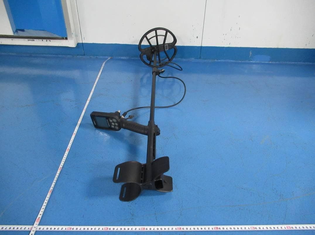
2AJJ2-SIMPLEX
Jan 17, 2020METAL DETECTOR
Equipment Class
DXX - Part 15 Low Power Communication Device Transmitter
2AJJ2-WANDER
Jan 17, 2020WIRELESS MODULE
Equipment Class
DXX - Part 15 Low Power Communication Device Transmitter