2AK7ELBP08Wireless Security Camera S4
VuPoint Solutions Inc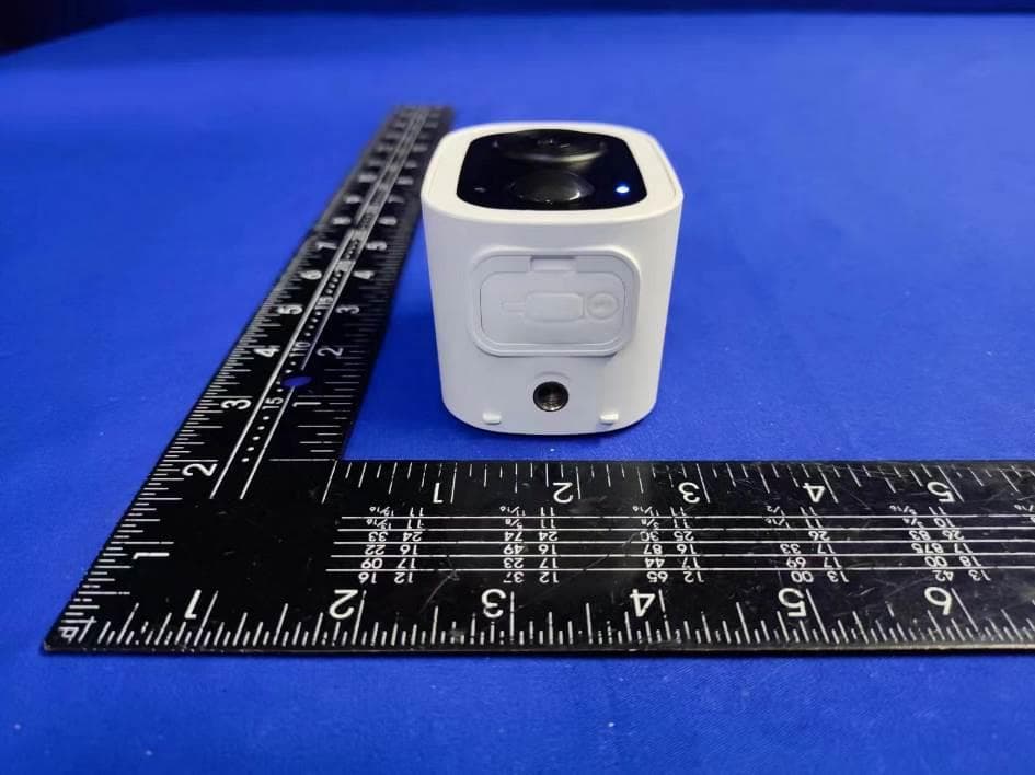
Click to zoom
Application Details
- Equipment Class
- DTS - Digital Transmission System
- Date of Grant
- Aug 18, 2024
- Application Purpose
- Original Equipment
- Date of Application
- Aug 18, 2024
- Equipment Note
- Wireless Security Camera S4
- Frequency Range
- 2412.00000000 - 2462.00000000
- Company
- VuPoint Solutions Inc
- Country
- United States
Documents & Files
Document Text
Text extracted from the exhibit documents filed with the FCC. Open a document above to read the original.
Users Manual
VuPoint (Europe) Company Limited: 1 Devon Way, Longbridge Technology Park, Longbridge, Birmingham B31 2TS, UK VuPoint Solutions, Inc. (USA): 12339 Denholm Dr, El Monte, CA 91732 For additional info, visit our website at ToucanSolution.com Items included Wireless Security Camera S4 Wall Anchors x3 Mounting Screws x3 Camera Mount USB Charging Cable TWC400S | TWC400S-EC USER MANUAL Wireless Security Camera S4 User Manual TWC400S USER MANUAL Wireless Security Camera S4 1. Camera Lens 2. Microphone 3. Motion Sensor 4. LED Indicator 5. Speaker 6. Camera Mount Screw Hole 7. SET / Power ON Button 8. Micro SD Card Slot 9. RST / Power OFF Pinhole Button 10. USB Charging Port 1 2 6 7 8 9 10 3 4 5 Get to know your Wireless Security Camera S4 1 Download the Toucan App for Android or iOS Scan QR code or visit www.toucansolution.com/pages/toucan-smart-home-app Ensure your Wi-Fi is set to 2.4Ghz before commencing the pairing process (5Ghz not supported) 2 Open the app and create a free account Tap the dashboard, then tap the "+" button. 3 Press and hold the SET button until LED light blinks to enter the setup mode 4 Follow the instruction in the Toucan App to complete the setup 5 Flashing BLUE Flashing PURPLE Flashing RED Setup Mode Connecting to cloud server, DO NOT TURN OFF POWER Connection Failed LED Description Setup your Wireless Security Camera S4 Charge your Wireless Security Camera S4 Open the USB plug cover, plug in the USB cable to charge the camera. Recommend to fully charge the device before 1st use. LED Description Solid RED Solid BLUE Charging Battery Battery Fully Charged 1 Mark the holes 6 Tighten the mount Install your Wireless Security Camera S4 For detailed setup procedure, please refer to the Toucan website (www.toucansolution.com) or scan the QR code. tighten FCC Statement Warning: Changes or modifications to this unit not expressly approved by the party responsible for compliance could void the user’s authority to operate the equipment. NOTE: This equipment has been tested and found to comply with the limits for a Class B digital device, pursuant to Part 15 of the FCC Rules. These limits are designed to provide reasonable protection against harmful interference in a residential installation. This equipment generates, uses and can radiate radio frequency energy and, if not installed and used in accordance with the instructions, may cause harmful interference to radio communications. However, there is no guarantee that interference will not occur in a particular installation. If this equipment does cause harmful interference to radio or television reception, which can be determined by turning the equipment off and on, the user is encouraged to try to correct the interference by one or more of the following measures: • Reorient or relocate the receiving antenna. • Increase the separation between the equipment and receiver. • Connect the equipment into an outlet on a circuit different from that to which the receiver is connected. • Consult the dealer or an experienced radio/TV technician for help. This device complies with Part 15 of the FCC Rules. Operation is subject to the following two conditions: (1) This device may not cause harmful interference. (2) This device must accept any interference received, including interference that may cause undesired operation. RF Exposure Compliance This equipment complies with FCC radiation exposure limits set forth for an uncontrolled environment. This equipment should be installed and operated with minimum distance 20cm between the radiator and your body. Please register to activate your 1-year free warranty within the App or by visiting our website: www.toucansolution.com. Proof of purchase in the form of a bill of sale or receipted invoice, which is evidence that the unit is within the warranty period, must be presented to obtain warranty service. VuPoint Solutions and VuPoint (Europe) Company Limited (herein referred to as “VuPoint”, “us”, “we”, or “our”) warrants this Toucan Product (including any included accessories) against defects in material and workmanship as follows: For 1 year (12 months) from date of original retail purchase of this Product, if Product is used primarily for personal, family, or household purposes (“Household Consumer Use”), VuPoint will repair or replace the Product, at its sole discretion, if the Product is determined to be defective due to material or workmanship. If Product is used for any other purpose than Household Consumer Use, including but not limited to commercial, industrial, or other non-household purposes, VuPoint will repair or replace the Product at no charge, at its sole discretion, if the Product is determined to be defective due to material or workmanship. Before returning the product, please contact us for help and support. Details of your local customer support can be found on our website: www.toucansolution.com To obtain warranty services, you must deliver the Product at your cost in either its original packaging or packaging that affords equivalent degree of protection as the original packaging to the VuPoint service facility. Please deliver the Product with an explanation of the defect, the dated sales receipt, a return address, and contact details. Please allow 7 working days for the Product to be tested for defects. This warranty does not cover customer instruction, installation, set up adjustments or signal reception problems. This warranty does not cover cosmetic damage or damage due to acts of God, accident, misuse, abuse, negligence, commercial use, or modification of, or to any part of the Product. This warranty does not cover damage due to improper operation or maintenance, connection to improper voltage supply, or attempted repair by anyone other than VuPoint service center. This warranty does not cover Products sold AS IS or WITH ALL FAULTS, or consumables (such as fuses or batteries). This warranty is invalid if the factory applied serial number has been altered or removed from the …
Text truncated - open the document above for the full version.
Attestation Statements
Rev 1/26/2023 VuPoint Solutions Inc. Federal Communications Commission Authorization and Evaluation Division 7435 Oakland Mills Road Columbia, MD 21046 USA Date: 08-13-2024 Ref: Attestation Statements Part 2.911(d)(5)(i) Filing FCC ID: 2AK7ELBP08 VuPoint Solutions Inc. ("the applicant")certifies that the equipment for which authorization is sought is not“covered” equipment prohibited from receiving an equipment authorization pursuant to section 2.903 of the FCC rules. Sincerely, (Applicantsignature) (Applicant printed name) Mitchell Kuan /Executive Vice President Rev 1/26/2023 VuPoint Solutions Inc. Federal Communications Commission Authorization and Evaluation Division 7435 Oakland Mills Road Columbia, MD 21046 USA Date: 08-13-2024 Ref: Attestation Statements Part 2.911(d)(5)(ii) Filing FCC ID: 2AK7ELBP08 VuPoint Solutions Inc. (“the applicant”) certifies that, as of the date of the filing of the application, the applicant is not identified on the Covered List(as a specifically named entity or any of its subsidiaries or affiliates) as an entity producing “covered” equipment. Sincerely, (Applicant signature) (Applicant printed name) Mitchell Kuan /Executive Vice President
Attestation Statements
Rev 1/26/2023 VuPoint Solutions Inc. 12339 Denholm Dr, El Monte, CA 91732 Federal Communications Commission Authorization and Evaluation Division 7435 Oakland Mills Road Columbia, MD 21046 USA Date:08-13-2024 Ref: Attestation Statements Part 2.911(d)(7) Filing FCC ID: 2AK7ELBP08 VuPoint Solutions Inc. certifies that, as of the date of the filing of the application, we designate ourselves as the U.S. agent for service of process. Designated U.S. Agent Information: FRN: 0026271080 Company Name: VuPoint Solutions Inc. Address: 12339 Denholm Dr, El Monte, CA 91732 Contact Name: Mitchell Kuan Contact Person: Executive Vice President Tel.: 626-893-5543 Email: [email protected] Sincerely, VuPoint Solutions Inc. Mitchell Kuan [Applicant signature]
External Photos
EUT EXTERNAL PHOTOGRAPHS ----------------The end----------------
ID Label/Location Info
US:TWC400S US:TWC400S-EC
Internal Photos
EUT INTERNAL PHOTOGRAPHS Antenna ----------------The end----------------
RF Exposure Info
FCC ID : 2AK7ELBP08 RF EXPOSURE EVALUATION According to FCC 1.1310: The criteria listed in the following table shall be used to evaluate the environment impact of human exposure to radio frequency (RF) Radiation as specified in §1.1307(b) Limits for Maximum Permissible Exposure (MPE) Frequency Range(MHz) Electric Field Strength(V/m) Magnetic Field Strength(A/m) Power Density(mW/cm 2 ) Average Time (A) Limits for Occupational/Control Exposures 300-1500 -- -- F/300 6 1500-100000 -- -- 5 6 (B) Limits for General Population/Uncontrol Exposures 300-1500 -- -- F/1500 6 1500-100000 -- -- 1 30 1.1 Friis transmission formula: Pd= (Pout*G)\ (4*pi*R 2 ) Where Pd= Power density in mW/cm 2 Pout=output power to antenna in mW G= Numeric gain of the antenna relative to isotropic antenna Pi=3.1416 R= distance between observation point and center of the radiator in 20cm Pd the limit of MPE, 1mW/cm 2 . If we know the maximum gain of the nd total power input to the antenna, through the calculation, we will know the distance where the MPE limit is reached. 1.2 Measurement Result Mode Max Measured power (dBm) Max tune-up power (dBm) Antenna gain Antenna Gain Numeric Evaluation result (mW/cm2 ) Power density Limits (mW/cm2 ) 2.4G WiFi 20.04 21 1.55 1.43 0.03579 1 ----------------THE END OF REPORT---------------
Test Report
Antenna test Report LBP08 SKYLIGHT ENGINEER DEPT APPROVAL BYDRAWN BY DATEVersion lijie Louisjiang 2024.07.01V01 SKY LIGHT Electronic (ShenZhen) Limited Website: http://www.skylight.com.hk(TEL)86-755-27511234 Content Antenna Performance{LBP08 Antenna} conclusion Instrumentation Performance 1 3 2 3/9 ITEMANTENNA SPEC Model NameLBP08--WiFi Frequency & Gain 2400MHz2420MHz2440MHz2460MHz2480MHz 1.541.491.551.360.99 Peak Gain(dBi) 1.55 Average Gain(dB) 1.38 Impedance50 Ω Antenna Size 12.5*17(mm) ManufactureSky Light Electronic (ShenZhen) Limited VSWR < 2.0 Antenna Typemetal Return Loss(dB) <-10 SPEC--WiFi 4/9 Instrumentation Performance 5/9 Instrumentation Performance 6/9 LBP08 in the lab 7/9 Antenna Size--WiFi 8/9 Antenna Size--WiFi 9/9 Performance of LBP08-2.4G 2D&3D sectional view XY Plane at 2.4GHz 10/9 Performance of LBP08-2.4G 2D&3D sectional view XZ Plane at 2.4GHz 11/9 Performance of LBP08-2.4G 2D&3D sectional view YZ Plane at 2.4GHz 12/9 Performance of LBP08 Efficiency & Gain 66% 66% 66% 65% 64% 65% 64% 64% 64% 62% 62% 62% 62% 62% 61% 60% 60% 59% 54% 56% 58% 60% 62% 64% 66% 68% Efficiencyof LBP08 Efficiency 1.54 1.37 1.58 1.53 1.49 1.65 1.60 1.59 1.55 1.48 1.44 1.38 1.36 1.32 1.26 1.05 0.99 0.70 0.00 0.20 0.40 0.60 0.80 1.00 1.20 1.40 1.60 1.80 Gainof LBP08 Gain 13/9 SKY LIGHT Electronic (ShenZhen) LimitedVersion: 01 Website: http://www.skylight.com.hk(TEL)86-755-27511234
Test Report
Report No. ENS2407090030W00901R Page 1 of 67 Ver.1.0 TEST REPORT Product Name : Wireless Security Camera S4 Model Number : TWC400S, TWC400S-ML, TWC400S-EC FCC ID : 2AK7ELBP08 Prepared for : VuPoint Solutions Inc. Address : 12339 Denholm Dr, El Monte, CA 91732 Prepared by : EMTEK (SHENZHEN) CO., LTD. Address : Building 69, Majialong Industry Zone,Nanshan District, Shenzhen, Guangdong, China Tel: (0755) 26954280 Fax: (0755) 26954282 Report Number : ENS2407090030W00901R Date(s) of Tests : July 11, 2024 to July 31, 2024 Date of issue : August 2, 2024 $二维码$ Report No. ENS2407090030W00901R Page 2 of 67 Ver.1.0 TABLE OF CONTENTS 1 TEST RESULT CERTIFICATION ........................................................................................................ 3 2 EUT TECHNICAL DESCRIPTION ...................................................................................................... 5 3 SUMMARY OF TEST RESULT ........................................................................................................... 6 4 TEST METHODOLOGY ...................................................................................................................... 7 4.1 GENERAL DESCRIPTION OF APPLIED STANDARDS .............................................................. 7 4.2 MEASUREMENT EQUIPMENT USED ........................................................................................ 7 4.3 DESCRIPTION OF TEST MODES ............................................................................................... 8 5 FACILITIES AND ACCREDITATIONS ................................................................................................ 9 5.1 FACILITIES .................................................................................................................................. 9 5.2 EQUIPMENT ................................................................................................................................ 9 5.3 LABORATORY ACCREDITATIONS AND LISTINGS ................................................................... 9 6 TEST SYSTEM UNCERTAINTY ....................................................................................................... 10 7 SETUP OF EQUIPMENT UNDER TEST ........................................................................................... 11 7.1 RADIO FREQUENCY TEST SETUP 1 ........................................................................................ 11 7.2 RADIO FREQUENCY TEST SETUP 2 ........................................................................................ 11 7.3 CONDUCTED EMISSION TEST SETUP ................................................................................... 14 7.4 BLOCK DIAGRAM CONFIGURATION OF TEST SYSTEM ....................................................... 15 7.5 SUPPORT EQUIPMENT ............................................................................................................ 15 8 TEST REQUIREMENTS .................................................................................................................... 16 8.1 DTS 6DB BANDWIDTH .............................................................................................................. 16 8.2 DTS 99% BANDWIDTH ............................................................................................................. 17 8.3 MAXIMUM PEAK CONDUCTED OUTPUT POWER ................................................................. 21 8.4 MAXIMUM POWER SPECTRAL DENSITY ............................................................................... 30 8.5 UNWANTED EMISSIONS IN NON-RESTRICTED FREQUENCY BANDS ............................... 34 8.6 RADIATED SPURIOUS EMISSION ........................................................................................... 43 8.7 CONDUCTED EMISSION TEST ................................................................................................ 64 8.8 ANTENNA APPLICATION .......................................................................................................... 67 Report No. ENS2407090030W00901R Page 3 of 67 Ver.1.0 1 TEST RESULT CERTIFICATION Applicant : VuPoint Solutions Inc. Address : 12339 Denholm Dr, El Monte, CA 91732 Manufacturer : VuPoint Solutions Inc. Address : 12339 Denholm Dr, El Monte, CA 91732 EUT : Wireless Security Camera S4 Model Name : TWC400S, TWC400S-ML, TWC400S-EC Trademark : N/A Measurement Procedure Used: APPLICABLE STANDARDS STANDARD TEST RESULT FCC 47 CFR Part 2, Subpart J FCC 47 CFR Part 15, Subpart C PASS The above equipment was tested by EMTEK(SHENZHEN) CO., LTD. The test data, data evaluation, test procedures, and equipment configurations shown in this report were made in accordance with the procedures given in ANSI C63.10 (2013) and the energy emitted by the sample EUT tested as described in this report is in compliance with the requirements of FCC Rules Part 2, Part 15.247. The test results of this report relate only to the tested sample identified in this report. Date of Test : July 11, 2024 to July 31, 2024 Prepared by : Una Yu /Editor Reviewer : Joe Xia /Supervisor Approve & Authorized Signer : Lisa Wang/Manager Report No. ENS2407090030W00901R Page 4 of 67 Ver.1.0 Modified History Version Report No. Revision Date Summary Ver.1.0 ENS2407090030W00901R / Original Report Report No. ENS2407090030W00901R Page 5 of 67 Ver.1.0 2 EUT TECHNICAL DESCRIPTION Characteristics Description Product: Wireless Security Camera S4 Model Number: TWC400S, TWC400S-ML, TWC400S-EC Sample Number: 2# IEEE 802.11 WLAN Mode Supported: 802.11b 802.11g 802.11n(20MHz channel bandwidth) Modulation: DSSS with DBPSK/DQPSK/CCK for 802.11b; OFDM with BPSK/QPSK/16QAM/64QAM for 802.11g/n; Operating Frequency Range: 2412-2462MHz for 802.11b/g/n(HT20); Number of Channels: 11 channels for 802.11b/g/n(HT20); Transmit Power Max(Peak): 20.04 dBm Antenna Port: Antenna port 1, Antenna port 2 Antenna Type: Metal Antenna Antenna Gain: 1.55 dBi Power Supply: DC5V/2A DC 3.6V from Batte…
Text truncated - open the document above for the full version.
Test Report
Report No. ENS2407090030W00901R Page 38 of 67 Ver.1.0 8.5 UNWANTED EMISSIONS IN NON-RESTRICTED FREQUENCY BANDS 8.5.1 Applicable Standard According to FCC Part15.247(d) and KDB 558074 D01 15.247 Meas Guidance v05r02 According to RSS-247, 5.5 8.5.2 Conformance Limit According to FCC Part 15.247(d): In any 100 kHz bandwidth outside the frequency band in which the spread spectrum or digitally modulated device is operating, the RF power that is produced shall be at least 20 dB below that in the 100 kHz bandwidth within the band that contains the highest level of the desired power, based on either an RF conducted or a radiated measurement, provided that the transmitter demonstrates compliance with the peak conducted power limits. If the transmitter complies with the conducted power limits based on the use of root-mean-square averaging over a time interval, as permitted undersection 5.4(d), the attenuation required shall be 30 dB instead of 20 dB. Attenuation below the general field strength limits specified in RSS-Gen is not required. 8.5.3 Test Configuration Test according to clause 6.1 radio frequency test setup 8.5.4 Test Procedure The transmitter output (antenna port) was connected to the spectrum analyzer Reference level measurement Establish a reference level by using the following procedure: Set instrument center frequency to DTS channel center frequency. Set the span to ≥ 1.5 times the DTS bandwidth. Set the RBW = 100 kHz. Set the VBW ≥ 3 x RBW. Set Detector = peak. Set Sweep time = auto couple. Set Trace mode = max hold. Allow trace to fully stabilize. Use the peak marker function to determine the maximum PSD level. Note that the channel found to contain the maximum PSD level can be used to establish the reference level. Band-edge measurement Use the following spectrum analyzer settings: Span = wide enough to capture the peak level of the emission operating on the channel closest to the band-edge, as well as any modulation products which fall outside of the authorized band of operation Set RBW 1% of the span=100kHz Set VBW 3 x RBW Set Sweep = autoSet Detector function = peakSet Trace = max hold Allow the trace to stabilize. Set the marker on the emission at the bandedge, or on the highest modulation product outside of the band, if this level is greater than that at the bandedge. Enable the marker-delta function, then use the marker-to-peak function to move the marker to the peak of the in-band emission. The marker-delta value now displayed must comply with the limit specified in this Section. Emission level measurement Set the center frequency and span to encompass frequency range to be measured. Set the RBW = 100 kHz. Set the VBW =300 kHz. Set Detector = peak Sweep time = auto couple. Trace mode = max hold. Allow trace to fully stabilize. Use the peak marker function to determine the maximum amplitude level. Ensure that the amplitude of all unwanted emissions outside of the authorized frequency band (excluding restricted frequency bands) are attenuated by at least the minimum requirements . Report the three highest emissions relative to the limit. Report No. ENS2407090030W00901R Page 39 of 67 Ver.1.0 8.5.5 Test Results Temperature: 25 ̊C Relative Humidity: 45 ATM Pressure: 1011 mbar Note: All theantenna(Antenna 1)and modes(802.11b/g/n)have been tested and the worst(Antenna 1,802.11b) resultrecorded was report as below: Band edge measurements TestMode Antenna ChName Frequency [MHz] RefLevel[dBm] Result[dBm] Limit[dBm] Verdict 11B Ant1 Low 2412 4.16 -34.96 ≤-25.84 PASS High 2462 4.63 -37.76 ≤-25.37 PASS 11G Ant1 Low 2412 -0.56 -31.01 ≤-30.56 PASS High 2462 1.32 -37.16 ≤-28.68 PASS 11N20SISO Ant1 Low 2412 1.65 -32.08 ≤-28.35 PASS High 2462 1.71 -38.28 ≤-28.29 PASS Report No. ENS2407090030W00901R Page 40 of 67 Ver.1.0 11B_Ant1_Low_2412 11B_Ant1_High_2462 11G_Ant1_Low_2412 Report No. ENS2407090030W00901R Page 41 of 67 Ver.1.0 11G_Ant1_High_2462 11N20SISO_Ant1_Low_2412 11N20SISO_Ant1_High_2462 Report No. ENS2407090030W00901R Page 42 of 67 Ver.1.0 Conducted Spurious Emission TestMode Antenna Frequency[MHz] FreqRange [Mhz] RefLevel [dBm] Result [dBm] Limit [dBm] Verdict 11B Ant1 2412 Reference 3.35 3.35 --- PASS 30~1000 3.35 -69.26 ≤-26.65 PASS 1000~26500 3.35 -52.6 ≤-26.65 PASS 2437 Reference 3.86 3.86 --- PASS 30~1000 3.86 -68.13 ≤-26.14 PASS 1000~26500 3.86 -50.53 ≤-26.14 PASS 2462 Reference 4.60 4.60 --- PASS 30~1000 4.60 -69.42 ≤-25.4 PASS 1000~26500 4.60 -49.79 ≤-25.4 PASS 11G Ant1 2412 Reference 1.60 1.60 --- PASS 30~1000 1.60 -69.05 ≤-28.4 PASS 1000~26500 1.60 -52.84 ≤-28.4 PASS 2437 Reference -1.85 -1.85 --- PASS 30~1000 -1.85 -69.13 ≤-31.85 PASS 1000~26500 -1.85 -52.97 ≤-31.85 PASS 2462 Reference -0.77 -0.77 --- PASS 30~1000 -0.77 -69.33 ≤-30.77 PASS 1000~26500 -0.77 -47.38 ≤-30.77 PASS 11N20SISO Ant1 2412 Reference -1.81 -1.81 --- PASS 30~1000 -1.81 -69.6 ≤-31.81 PASS 1000~26500 -1.81 -53.33 ≤-31.81 PASS 2437 Reference -1.99 -1.99 --- PASS 30~1000 -1.99 -69.25 ≤-31.99 PASS 1000~26500 -1.99 -39.66 ≤-31.99 PASS 2462 Reference 1.48 1.48 --- PASS 30~1000 1.48 -68.81 ≤-28.52 PASS 1000~26500 1.48 -53.57 ≤-28.52 PASS Report No. ENS2407090030W00901R Page 43 of 67 Ver.1.0 11B_Ant1_2412_0~Reference 11B_Ant1_2412_30~1000 11B_Ant1_2412_1000~26500 Report No. ENS2407090030W00901R Page 44 of 67 Ver.1.0 11B_Ant1_2437_0~Reference 11B_Ant1_2437_30~1000 11B_Ant1_2437_1000~26500 Report No. ENS2407090030W00901R Page 45 of 67 Ver.1.0 11B_Ant1_2462_0~Reference 11B_Ant1_2462_30~1000 11B_Ant1_2462_1000~26500 Report No. ENS2407090030W00901R Page 46 of 67 Ver.1.0 11G_Ant1_2412_0~Reference 11G_Ant1_2412_30~1000 11G_Ant1_2412_1000~26500 Report No. ENS2407090030W00901R Page 47 of 67 Ver.1.0 11G_Ant1_2437_0~Reference 11G_Ant1_2437_30~1000 11G_Ant1_2437_1000~26500 Report No. ENS2407090030W00901R Page 48 of 67 Ver.1.0 11G_Ant1_2462_0~Reference 11G_Ant1_2462_30~1000 11G_Ant1_2462_1000~26500 Report No. ENS2407090030W00901R Page 49 of 67 Ver.1.0 11N20SISO_Ant1_2412_0~Reference 11N20SISO_Ant1_2412_30~1000 1…
Text truncated - open the document above for the full version.
Test Setup Photos
TEST SETUP PHOTOGRAPHS 1.1. Photos of Conducted Emission Measurement 1.2. Photos of Radiation Emission Measurement Spurious Emission Test Setup (Below 1GHz) Spurious Emission Test Setup (Above 1GHz) ----------------The end----------------
Contact Information
Applicant
Mitchell Kuan(Executive Vice President)
Test Firm
EMTEK (Shenzhen) Co., Ltd.Lisa Wang
[email protected]8675526954280
Technical Specifications
| # | Rule Parts | Frequency Range | Power Output |
|---|---|---|---|
| 1 | 15C | 2.41 GHz - 2.46 GHz | 100.00 mW |
Other Applications from VuPoint Solutions Inc
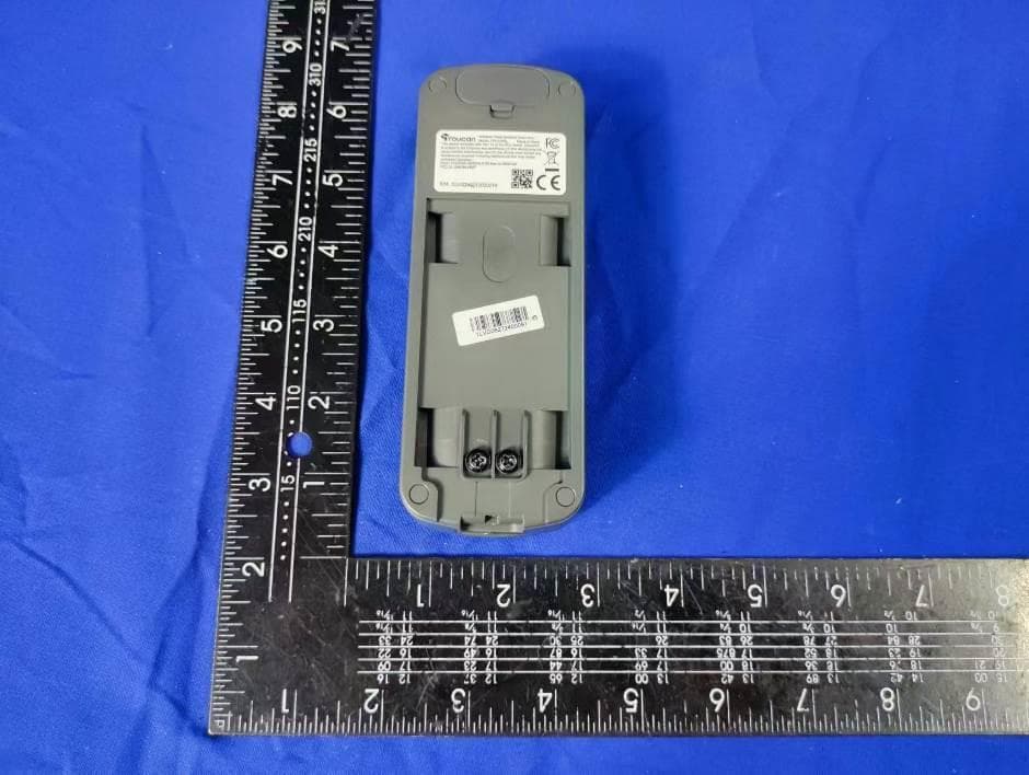
2AK7ELVD07
Sep 24, 2024Wireless Video Doorbell Dual Lens,Wireless Video Doorbell V3
Equipment Class
DSC - Part 15 Security/Remote Control Transmitter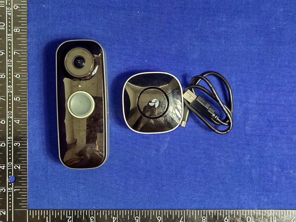
2AK7ELVD05
Jan 03, 2023Wireless Video Doorbell PRO
Equipment Class
DSC - Part 15 Security/Remote Control Transmitter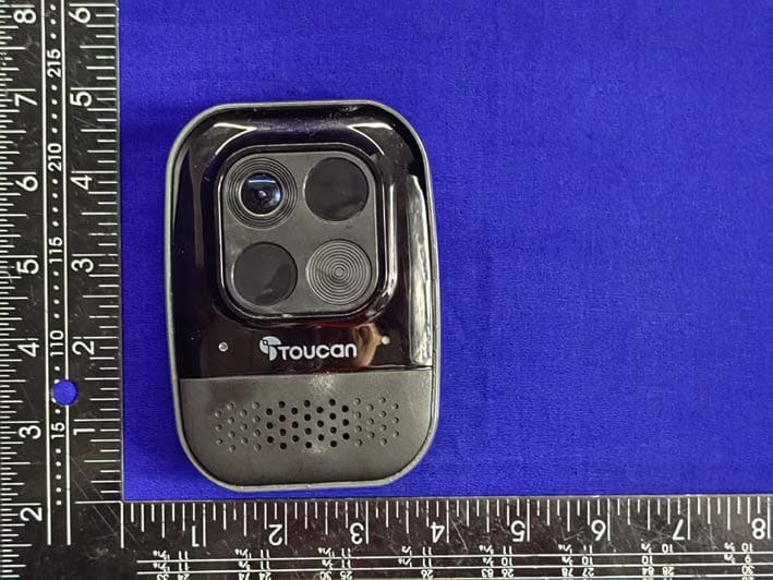
2AK7ELBP05
Nov 09, 2022Wireless Security Camera PRO
Equipment Class
DXX - Part 15 Low Power Communication Device Transmitter