2AK9F-FT4POWER BANKS FOR USE IN PORTABLE APPLICATIONS
Titan Company Limited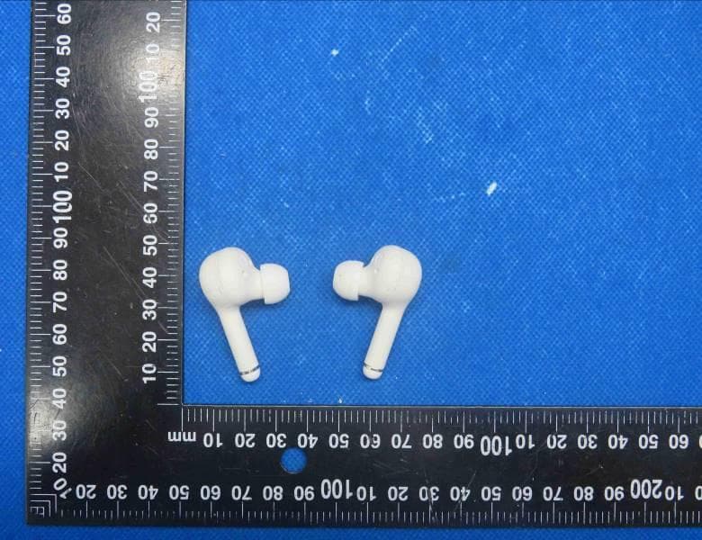
Click to zoom
Application Details
- Equipment Class
- DSS - Part 15 Spread Spectrum Transmitter
- Date of Grant
- Oct 07, 2023
- Application Purpose
- Original Equipment
- Date of Application
- Oct 07, 2023
- Equipment Note
- POWER BANKS FOR USE IN PORTABLE APPLICATIONS
- Frequency Range
- 2402.00000000 - 2480.00000000
- Company
- Titan Company Limited
- Country
- India
Documents & Files
Document Text
Text extracted from the exhibit documents filed with the FCC. Open a document above to read the original.
Users Manual
Wireless Earphones user manual 【1】【2】【3】 Product parameters ◎Wireless version: V5.3 ◎Working range: barrier-free 10 meters ◎Wireless frequency: 2.402-2.480GHz ◎ Charge and discharge cycle: ≥300 times ◎Charging box capacity: 800mAh ◎Charging voltage: DC5V-800mA ◎ Charging time: 1.5 hours ◎Talk time: about 3.2 hours (80% volume) ◎Play music: about 4 hours (80% volume) ◎Headphone built-in battery: lithium battery 3.7V, 70mAh Note: The specifications and parameters of this product are all laboratory test data, which will be different in different environments; the product is constantly being upgraded and improved, and the specific functions and product pictures may be slightly different from the actual product, please refer to the actual product. Touch method • Power on: open the cover turn on • Power off: Put the earphone into the charging box, and close the charging box cover to turn off • Play/Pause: Click once on the left/right earphones • Previous song: Three clicks on the left earphone • Next song: Three clicks on the right earphone • Voice Assistant: Press and hold the left/right earphones for 2 seconds • Answer a call: Click once on the left/right earphones • Hang up the phone: Double click on the left/right earphone • Refuse to answer a call: Press and hold the left/right earphones for 2 seconds • Increase volume: Double click on the right earphone • Reduce volume: Double click on the left earphone 【4】【5】【6】 Charging box LED indicator status • Open/close lid indicator light: green light on • When the charging box charges the earphones: the indicator light is on for 8 seconds and then off until the earphones are fully charged. • Charging indicator light for the charging box: The orange light flashes, and remains on for a long time when fully charged • Charging box low battery reminder: LED flashing Universal wireless connection operation 1. Please put the wireless headset and mobile phone (or other connected devices) together; 2. Make sure the headset is powered on, open the charging box cover or remove the headset from the charging box, make sure that the left and right headsets are connected, the headset can enter the pairing mode; 3. Turn on the Wireless function of the user's mobile phone (or other Wireless device), and search or scan. At this time, the mobile phone will search for all nearby Wireless devices. Click the corresponding Wireless model name to connect. After successfully pairing and connecting, you can make a headset call , Listening to songs, etc. Precautions 1. Never use corrosive cleaning agents to clean this product; 2. Do not allow this product to heat or come close to fire sources, such as cooking stoves; 3. Do not expose this product to direct sunlight for a long time to avoid high temperature; 4. Do not dispose of this product in fire to avoid explosion; 5. Do not try to disassemble this product to make any modifications, because it does not contain any maintenance components; 6. Do not use this product in the rain; 7. If you do not plan to use this product for a long period of time, please store it in a dry environment.And charge the headset at least once a month to extend the life and avoid extreme temperatures and dust. Considerations when connecting wirelessly 1. Please control the distance between the wireless headset and the mobile phone (or other connected equipment) within 1 meter, the closer the better; 2. You can put the earphone in the charging box and open the charging box cover to connect; 3. When the headphones are removed from the charging box and connected, make sure that the left and right headphones are connected; 4. Do not close the charging box cover during the connection process; 5. The charging box needs to have enough power. If the headphones cannot be turned on when the cover is opened, put the headphones in the charging box, close the cover of the charging box and plug in the charger to charge for at least one hour; FCC Warnning: This equipment has been tested and found to comply with the limits for a Class B digital device, pursuant to part 15 of the FCC Rules. These limits are designed to provide reasonable protection againstharmful interference in a residential installation. This equipment generates, uses and can radiateradio frequency energy and, if not installed and used in accordance with the instructions, maycause harmful interference to radio communications. However, there is no guarantee thatinterference will not occur in a particular installation. If this equipment does cause harmfulinterference to radio or television reception, which can be determined by turning the equipmentoff and on, the user is encouraged to try to correct the interference by one or more of thefollowing measures: • Reorient or relocate the receiving antenna. • Increase the separation between the equipment and receiver. • Connect the equipment into an outlet on a circuit different from that to which the receiver is connected. • Consult the dealer or an experienced radio/TV technician for help. Caution: Any changes or modifications to this device not explicitly approved by manufacturer could void your authority to operate this equipment. This device complies with part 15 of the FCC Rules. Operation is subject to the following two conditions: (1)This device may not cause harmful interference, and (2) this device must accept any interference received, including interference that may cause undesired operation. This equipment complies with FCC radiation exposure limits set forth for an uncontrolled environment. This equipment should be installed and operated with minimum distance 0cm between the radiator and your body.
Cover Letter(s)
Sincerely, Name/Title: Somprabh Singh/HEAD DESIGN AND TECHNOLOGY Company: Titan Company Limited Address: Integrity, #193, Veerasandra, Electronics City P.O., Off Hosur Main Road Bangalore India Phone: 918066609000 Fax: N/A E-Mail: [email protected]
External Photos
Shenzhen HTT Technology Co., Ltd. Report No.: HTT202306513 Shenzhen HTT Technology Co.,Ltd. Tel: 0755-23595200 Fax: 0755-23595201 1F, Building B, Huafeng International Robotics Industrial Park,Hangcheng Road, Nanchang Community, Xixiang Street, Bao'an District, Guangdong Province, Shenzhen, China Page 1 of 7 Product Name: POWER BANKS FOR USE IN PORTABLE APPLICATIONS Model No.: FT4 EUT Constructional Details External Photo Report No.: HTT202306513 Shenzhen HTT Technology Co.,Ltd. Tel: 0755-23595200 Fax: 0755-23595201 1F, Building B, Huafeng International Robotics Industrial Park,Hangcheng Road, Nanchang Community, Xixiang Street, Bao'an District, Guangdong Province, Shenzhen, China Page 2 of 7 Report No.: HTT202306513 Shenzhen HTT Technology Co.,Ltd. Tel: 0755-23595200 Fax: 0755-23595201 1F, Building B, Huafeng International Robotics Industrial Park,Hangcheng Road, Nanchang Community, Xixiang Street, Bao'an District, Guangdong Province, Shenzhen, China Page 3 of 7 Report No.: HTT202306513 Shenzhen HTT Technology Co.,Ltd. Tel: 0755-23595200 Fax: 0755-23595201 1F, Building B, Huafeng International Robotics Industrial Park,Hangcheng Road, Nanchang Community, Xixiang Street, Bao'an District, Guangdong Province, Shenzhen, China Page 4 of 7 Report No.: HTT202306513 Shenzhen HTT Technology Co.,Ltd. Tel: 0755-23595200 Fax: 0755-23595201 1F, Building B, Huafeng International Robotics Industrial Park,Hangcheng Road, Nanchang Community, Xixiang Street, Bao'an District, Guangdong Province, Shenzhen, China Page 5 of 7 Report No.: HTT202306513 Shenzhen HTT Technology Co.,Ltd. Tel: 0755-23595200 Fax: 0755-23595201 1F, Building B, Huafeng International Robotics Industrial Park,Hangcheng Road, Nanchang Community, Xixiang Street, Bao'an District, Guangdong Province, Shenzhen, China Page 6 of 7 Report No.: HTT202306513 Shenzhen HTT Technology Co.,Ltd. Tel: 0755-23595200 Fax: 0755-23595201 1F, Building B, Huafeng International Robotics Industrial Park,Hangcheng Road, Nanchang Community, Xixiang Street, Bao'an District, Guangdong Province, Shenzhen, China Page 7 of 7 ------End------
ID Label/Location Info
Label and Location Size: L: 1.0cm*W: 0.5cm Label and Location FCC ID : 2AK9F-FT4
Internal Photos
Shenzhen HTT Technology Co., Ltd. Report No.: HTT202306513 Shenzhen HTT Technology Co.,Ltd. Tel: 0755-23595200 Fax: 0755-23595201 1F, Building B, Huafeng International Robotics Industrial Park,Hangcheng Road, Nanchang Community, Xixiang Street, Bao'an District, Guangdong Province, Shenzhen, China Page 1 of 2 Product Name: POWER BANKS FOR USE IN PORTABLE APPLICATIONS Model No.: FT4 EUT Constructional Details Internal Photo Antenna Report No.: HTT202306513 Shenzhen HTT Technology Co.,Ltd. Tel: 0755-23595200 Fax: 0755-23595201 1F, Building B, Huafeng International Robotics Industrial Park,Hangcheng Road, Nanchang Community, Xixiang Street, Bao'an District, Guangdong Province, Shenzhen, China Page 2 of 2 ------End------
RF Exposure Info
RF Exposure evaluation FCC ID: 2AK9F-FT4 1.1. Applicable Standard According to §1.1307(b)(1), systems operating under the provisions of this section shall be operated in a manner that ensures that the public is not exposed to radio frequency energy level in excess of the Commission’s guidelines. According to §1.1310 and §2.1093 RF exposure requirement KDB447498 v06: Mobile and Portable Devices RF Exposure Procedures and Equipment Authorization Policies 1.2. Requirement According to KDB447498 D01 General RF Exposure Guidance v06 Section 4.3.1 Standalone SAR test exclusion considerations: “Unless specifically required by the published RF exposure KDB procedures, standalone 1-g head or body and 10-g extremity SAR evaluation for general population exposure conditions, by measurement or numerical simulation, is not required when the corresponding SAR Test Exclusion Threshold condition, listed below, is satisfied. These test exclusion conditions are based on source-based time-averaged maximum conducted output power of the RF channel requiring evaluation, adjusted for tune-up tolerance, and the minimum test separation distance required for the exposure conditions.22 The minimum test separation distance is determined by the smallest distance from the antenna and radiating structures or outer surface of the device, according to the host form factor, exposure conditions and platform requirements, to any part of the body or extremity of a user or bystander (see 5) of section 4.1). To qualify for SAR test exclusion, the test separation distances applied must be fully explained and justified by the operating configurations and exposure conditions of the transmitter and applicable host platform requirements, typically in the SAR measurement or SAR analysis report, according to the required published RF exposure KDB procedures. When no other RF exposure testing or reporting is required, a statement of justification and compliance must be included in the equipment approval, in lieu of the SAR report, to qualify for the SAR test exclusion. When required, the device specific conditions described in the other published RF exposure KDB procedures must be satisfied before applying these SAR test exclusion provisions; for example, handheld PTT two-way radios, handsets, laptops & tablets etc.23 “ [(max. power of channel, including tune-up tolerance, mW)/ (min. test separation distance, mm)] · [√f (GHz)] ≤ 3.0 for 1-g SAR and ≤ 7.5 for 10-g extremity SAR, where: • f (GHz) is the RF channel transmit frequency in GHz • Power and distance are rounded to the nearest mW and mm before calculation • The result is rounded to one decimal place for comparison • 3.0 and 7.5 are referred to as the numeric thresholds in the step 2 below The test exclusions are applicable only when the minimum test separation distance is ≤ 50 mm and for transmission frequencies between 100 MHz and 6 GHz. When the minimum test separation distance is < 5 mm, a distance of 5 mm according to 5) in section 4.1 is applied to determine SAR test exclusion. 1.3. Manufacturing tolerance GFSK (Peak) Channel Channel 0 Channel 39 Channel 78 Target (dBm) -1.0 0.0 0.0 Tolerance ±(dB) 1.0 1.0 1.0 π/4DQPSK (Peak) Channel Channel 0 Channel 39 Channel 78 Target (dBm) 0.0 1.0 0.0 Tolerance ±(dB) 1.0 1.0 1.0 8-DPSK (Peak) Channel Channel 0 Channel 39 Channel 78 Target (dBm) 0.0 1.0 0.0 Tolerance ±(dB) 1.0 1.0 1.0 Page 2 of 2 2. E v a l u a t i o n R e s u l t Evaluation Results Band/Mode f (GHz) Antenna Distance (mm) RF output power (including tune-up tolerance) SAR Test Exclusion Threshold SAR Test Exclusion dBm mW BT 2.450 5 2.0 1.5849 0.4962<3.0 Yes 3. C o n c l u s i o n The measurement results comply with the FCC Limit per 47 CFR 2.1093 for the uncontrolled RF Exposure and SAR Exclusion Threshold per KDB 447498 v06 .....................End of Report.........................
Test Report
1. Antenna Description: Antenna type PIFA antenna Model FT4 Frequency range 2400-2500MHz Manufacturer Dongguan Cheerlink Electronic Technology Co., LTD ANT Peak Gain 1.58 dBi 2. Antenna Photo: Length: 12.15mm Width: 9.20mm 3. Test Equipment & Conditions 3.1 Test instrument VSWR is tested using Agilent E5071B connected to a hand mechanism, and the status is free space. 3.2 Test environment and methods 4.Antenna Radiation Pattern 2400MHz 2450MHz 2500MHz
Test Report
Shenzhen HTT Technology Co., Ltd. Report No.: HTT202306513F01 This results shown in this test report refer only to the sample(s) tested, this test report cannot be reproduced, except in full, without prior written permission of the company. The report would be invalid without specific stamp of test institute and the signatures of compiler and approver. Page 1 of 46 TEST Report Applicant: Titan Company Limited Address of Applicant: Integrity, #193, Veerasandra, Electronic City P.O., Off Hosur Main Road, Bangalore-560100 Karnataka, India Manufacturer : Dongguan Cheerlink Electronic Technology Co., LTD Address of Manufacturer : Bulding 1, No.4 Fulong, Shipai, Dongguan City, GuangDong Province, China Equipment Under Test (EUT) Product Name: POWER BANKS FOR USE IN PORTABLE APPLICATIONS Model No.: FT4 Series model: N/A Trade Mark: Fastrack FCC ID: 2AK9F-FT4 Applicable standards: FCC CFR Title 47 Part 15 Subpart C Section 15.247 Date of sample receipt: Jun.30,2023 Date of Test: Jun.30,2023~Jul.05,2023 Date of report issued: Jul.05,2023 Test Result : PASS * * In the configuration tested, the EUT complied with the standards specified above. Report No.: HTT202306513F01 Shenzhen HTT Technology Co.,Ltd. Tel: 0755-23595200 Fax: 0755-23595201 1F, Building B, Huafeng International Robotics Industrial Park, Hangcheng Road,Nanchang Community, Xixiang Street, Bao'an District, Shenzhen, Guangdong, China Page 2 of 46 1. Version Version No. Date Description 00 Jul.05,2023 Original Tested/ Prepared By Date: Jul.05,2023 Project Engineer Check By: Date: Jul.05,2023 Reviewer Approved By : Date: Jul.05,2023 Authorized Signature Report No.: HTT202306513F01 Shenzhen HTT Technology Co.,Ltd. Tel: 0755-23595200 Fax: 0755-23595201 1F, Building B, Huafeng International Robotics Industrial Park, Hangcheng Road,Nanchang Community, Xixiang Street, Bao'an District, Shenzhen, Guangdong, China Page 3 of 46 2. Contents Page 1. VERSION ........................................................................................................................................................ 2 2. CONTENTS .................................................................................................................................................... 3 3. TEST SUMMARY ........................................................................................................................................... 4 4. GENERAL INFORMATION ............................................................................................................................ 5 4.1. GENERAL DESCRIPTION OF EUT ................................................................................................................ 5 4.2. TEST MODE ............................................................................................................................................... 7 4.3. DESCRIPTION OF SUPPORT UNITS .............................................................................................................. 7 4.4. DEVIATION FROM STANDARDS .................................................................................................................... 7 4.5. ABNORMALITIES FROM STANDARD CONDITIONS ........................................................................................... 7 4.6. TEST FACILITY ........................................................................................................................................... 7 4.7. TEST LOCATION ......................................................................................................................................... 7 4.8. ADDITIONAL INSTRUCTIONS ........................................................................................................................ 7 5. TEST INSTRUMENTS LIST ........................................................................................................................... 8 6. TEST RESULTS AND MEASUREMENT DATA ........................................................................................... 9 6.1. CONDUCTED EMISSIONS ............................................................................................................................ 9 6.2. CONDUCTED PEAK OUTPUT POWER ......................................................................................................... 12 6.3. 20DB EMISSION BANDWIDTH .................................................................................................................... 13 6.4. FREQUENCIES SEPARATION ...................................................................................................................... 17 6.5. HOPPING CHANNEL NUMBER .................................................................................................................... 19 6.6. DWELL TIME ............................................................................................................................................ 21 6.7. BAND EDGE ............................................................................................................................................. 26 6.7.1. Conducted Emission Method ......................................................................................................... 26 6.7.2. Radiated Emission Method ............................................................................................................ 30 6.8. SPURIOUS EMISSION ................................................................................................................................ 32 6.8.1. Conducted Emission Method ......................................................................................................... 32 6.8.2. Radiated Emission Method ............................................................................................................ 37 6.9. ANTENNA REQUIREMENT .......................................................................................................................... 45 7. TEST SE…
Text truncated - open the document above for the full version.
Test Setup Photos
Shenzhen HTT Technology Co., Ltd. Report No.: HTT202306513 Shenzhen HTT Technology Co.,Ltd. Tel: 0755-23595200 Fax: 0755-23595201 1F, Building B, Huafeng International Robotics Industrial Park,Hangcheng Road, Nanchang Community, Xixiang Street, Bao'an District, Guangdong Province, Shenzhen, China Page 1 of 2 Product Name: POWER BANKS FOR USE IN PORTABLE APPLICATIONS Model No.: FT4 Test Setup Photo Radiated Emission Report No.: HTT202306513 Shenzhen HTT Technology Co.,Ltd. Tel: 0755-23595200 Fax: 0755-23595201 1F, Building B, Huafeng International Robotics Industrial Park,Hangcheng Road, Nanchang Community, Xixiang Street, Bao'an District, Guangdong Province, Shenzhen, China Page 2 of 2 Conducted Emission ------End------
Contact Information
Applicant
Somprabh Kumar Singh(Mr.)
Test Firm
Shenzhen HTT Technology Co.,Ltd.Kevin Yang
[email protected]86-755-23595200
Technical Specifications
| # | Rule Parts | Frequency Range | Power Output |
|---|---|---|---|
| 1 | 15C | 2.40 GHz - 2.48 GHz | 1.30 mW |
Other Applications from Titan Company Limited
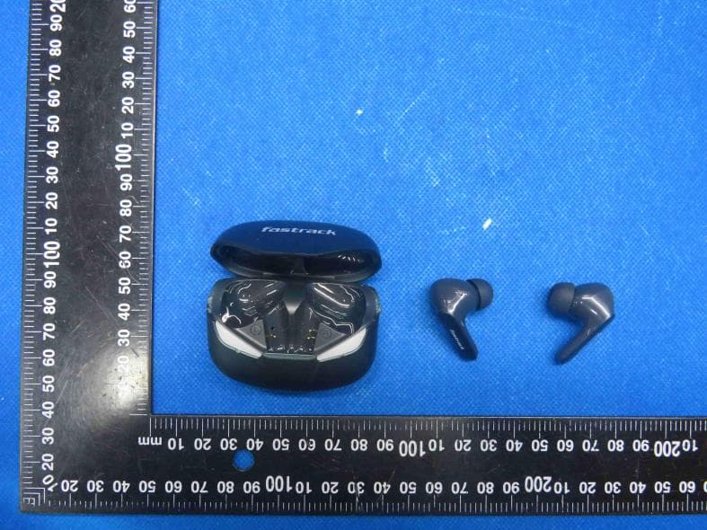
2AK9F-FT3
Oct 07, 2023POWER BANKS FOR USE IN PORTABLE APPLICATIONS
Equipment Class
DSS - Part 15 Spread Spectrum Transmitter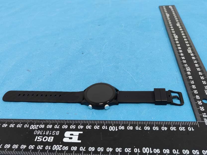
2AK9F-38110
Sep 05, 2023SMART WATCH
Equipment Class
DSS - Part 15 Spread Spectrum Transmitter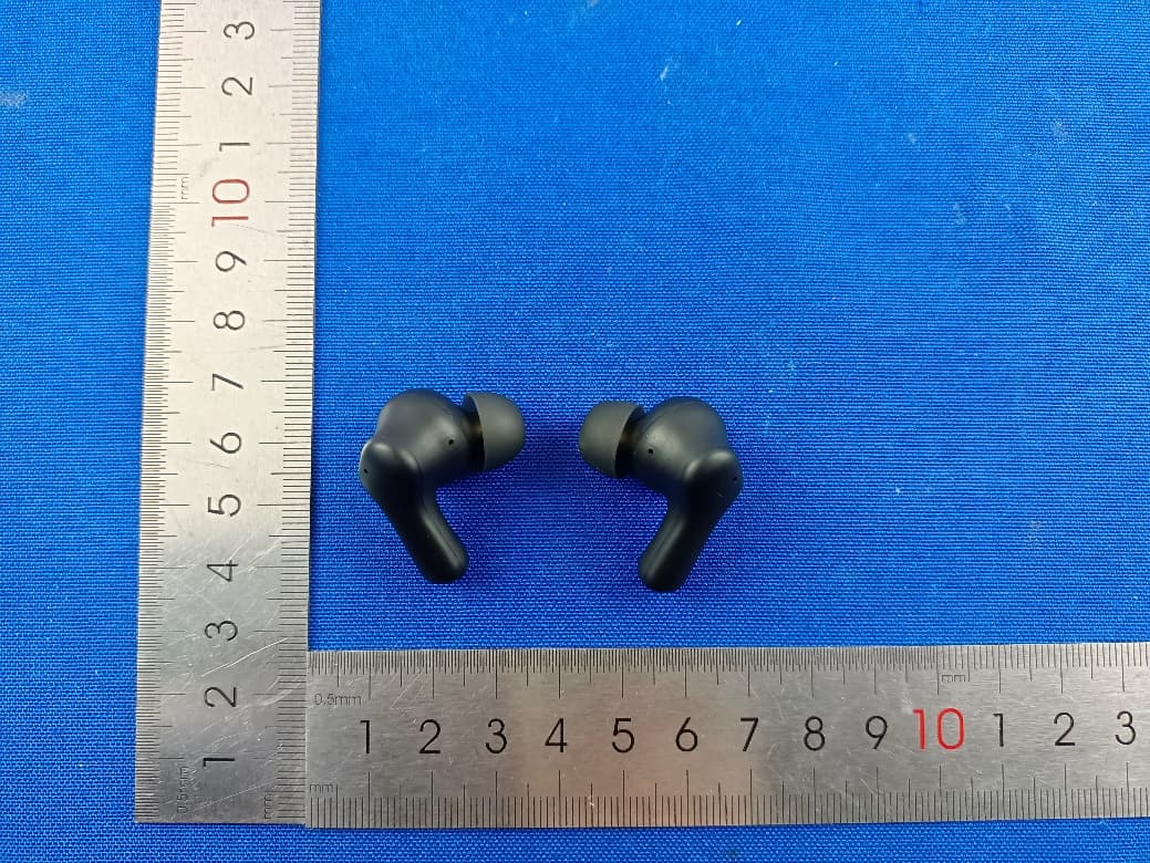
2AK9F-FT9
Aug 30, 2023Wireless Earphone
Equipment Class
DTS - Digital Transmission System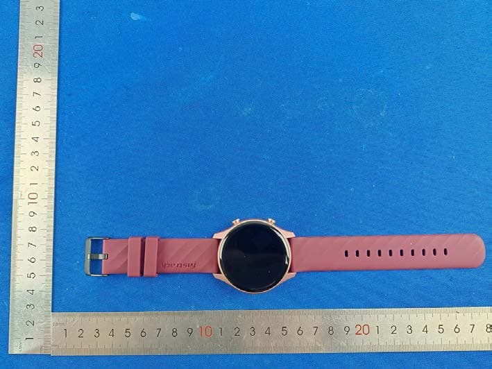
2AK9F-38112
Jul 26, 2023SMART WATCH
Equipment Class
DSS - Part 15 Spread Spectrum Transmitter
2AK9F-FT8
Apr 22, 2023FPods FS100
Equipment Class
DSS - Part 15 Spread Spectrum Transmitter