2AKAF-CAM12AI Recorder II
Waylens Inc.
Click to zoom
Application Details
- Equipment Class
- DSS - Part 15 Spread Spectrum Transmitter
- Date of Grant
- Jul 12, 2023
- Application Purpose
- Original Equipment
- Date of Application
- Jul 12, 2023
- Equipment Note
- AI Recorder II
- Frequency Range
- 2402.00000000 - 2480.00000000
- Company
- Waylens Inc.
- Country
- United States
Documents & Files
Document Text
Text extracted from the exhibit documents filed with the FCC. Open a document above to read the original.
Users Manual
Connect your AI Recorder using this WiFi SSID and password, making sure to keep them in a safe place for future reference. AI Recorder What’s included with the AI Recorder Please ensure the AI Recor der and any necessary power components are secured and out of reach of passenger s. AI R ec or der AI Recorder Mount Plate & Adhesive AI Recorder Wedge Mount Plate & Adhesive Mini Philips Allen Key Installation Guide OBD-II Power Cor d (Optional) Power Cord (one of below) Direct Wir e Power Cor d 1 2 AI Recorder Click × 1 Force power on Click × 3 Flip on WiFi Direct Mode Press for 2s Mark an Event Press for 8s Restart the Camera Magic Button Solid BLUE Power On/Idle Solid RED Recording Blink BLUE Firmware Updating Solid GREEN 5s to Restart Update Success Solid RED 5s to Restart Update Fail Blink BLUE and RED Error Camera LED Solid Green Connected to the Server Solid Blue Connected to 4G but not the Server Off No network connections Network LED Solid Green Expansions (Aux Cam) in working Off No Expansions Expansion LED Road Facing Camera Expansion (AUX Cam) Cables Expansion Cables Locker Tamper proof panel w/ security screws Magic Button Driver Privacy Cover (optional) Driver Facing Camera Night Vision LightsNight Vision Lights Camera LED Road Facing Camera Pitch Adjuster Cover SD Card Slot Power SocketExternal Mounting bracket connection Network LED External AUX LED Al Recorder OverviewInstall Waylens Fleet App to verify the AI Recorder installation The Waylens Fleet App is the companion to the AI Recorder, providing the fleet administrator with an easy way to install, maintain, and diagnose the AI Recorder. Installation Check Points: ● Network/Cloud Connection ● External AUX cameras (if installed) ● Preview video ● Network Test ● Power Test Do not use mobile devices to access the AI Recorder while operating the vehicle. Park your vehicle in a safe location before accessing the App. Simply connect to the wifi network broadcasted by the AI recorder and then open the Waylens Fleet App. The wifi network name and password can be located on the camera label, or on the back of this installation guide. 43 Fleet Waylens requires a high endurance micro SD card (class 10 or higher MLC microSD card 32-512 GB), designed for continuous recording applications. While other cards will technically work with the AI Recorder, they are much more prone to card errors and failures. Installing your AI Recorder Park the car in a safe and convenient place for the installation Insert the microSD card (if not already installed) The new microSD card will be automatically formatted when the first time it was inserted to AI Recorder. Do not remove the microSD card while the AI Recorder is recording (the status LED illuminates red). Install power in the vehicle Direct Wire Power Cord 1. Make sure the vehicle is off. 2. Find the location and layout of your fuse box as well as the appropriate fuse type from the vehicle’s user manual. IMPORTANT NOTE: The recorder should only be wired on a fuse circuit which is non-essential. The users should never install the recorder on any safety system such as airbag, anti-lock braking systems, vehicle lights, driver assistance systems. NOTE: Professional installation assistance is recommended, if you are not familiar with identifying fuses in a vehicle and installing power system related items. 3. Connect the red ACC wire to a switched fuse via Fuse Tap Cable: a. A switched fuse is used to monitor the accessory power such as cigarette lighter, car radio, etc. They will be switched off after you turn off the car. Identify them by referring to the vehicle user manual or consulting a qualified professional. b. Verify the fuse is a switched fuse by using a multimeter to track voltage within the circuit across ignitions ON and OFF positions. 56 1 2 c. If confirmed as a switched power fuse, remove the identified switched fuse from the fuse panel. Use the fuse puller tool if available. d. Select the right Fuse Tap Cable for your vehicle. e. Insert the supplied 5 Amp fuse to the socket 2 if it’s not inserted yet. f. Insert the identified vehicle fuse into slot 3 on the Fuse Tap Cable. NOTE: The supplied 5Amp fuse MUST be placed in the uppermost socket, as shown below. Inline with the red cable. The original vehicle fuse is to be placed in the lower socket. 5 Amp 5 Amp g. Insert the Fuse Tap Cable into the fuse panel carefully. h. Insert the exposed ACC wire from the camera harness into the Fuse Tap Cable connector and crimp to secure the connection. 4. Connect the yellow B+ wire to a constant power fuse via Fuse Tap Cable. a. The constant power fuses are used to monitor constant power within a vehicle. They will not be switched off after you turn off the car. Identify them by referring to the vehicle manual or consulting a professional. b. Verify the fuse is a constant fuse by a multimeter to track voltage within the circuit across ignitions ON and OFF positions. c. If confirmed as a constant power fuse, remove the identified constant fuse from the fuse panel. Use the fuse puller tool if available. d. Refer steps 3.d to 3.h for the Fuse Tap Cable usage and connection. Ensure working on the yellow B+ wire and the right constant power fuse. 5. Connect the black GND wire to a chassis ground point, such as a bolt, that is directly touching a bare metal surface of the vehicle’s framework. 6. Route the wire with USB Type-C plug of the Direct Wire Power Cord to the expected camera mounting location on the windshield. 78 1 1 1 2 3 2 3 2 3 4 4 4 ACS Type (Min) ACN Type (Low profile mini) ATO/ACU Type (Regular) Direct Wire + + Acc B+ GND NOTE: Leave an extra few inches of cord length near the camera to insert the Type-C plug into the AI Recorder’s Power socket, and also to make mounting and dismounting the AI Recorder easier. Important: If your vehicle has side impact airbags, make sure the harness does not interfere with its ability to deploy. 7. Secure any excess wire after the recorder is mounted. The O…
Text truncated - open the document above for the full version.
Attestation Statements
U.S. AGENT LETTER OF ATTESTATION Date: 2023-06-12 FEDERAL COMMUNICATIONS COMMISSION Authorization and Evaluation Division 7435 Oakland Mills Road Columbia, MD 21046 Ref: Attestation Statements Part 2.911(d)(7) Filing FCC ID: 2AKAF-CAM12 Waylens Inc. ( “the Applicant”) certifies that, as of the date of the filing of the application, Waylens Inc. ( U.S. agent). is our designated U.S. agent for service of process for the above referenced FCC ID. Waylens Inc. ( “the Applicant”)accepts to maintain an agent for no less than one year after the grantee has terminated all marketing and importation or the conclusion of any Commission-related proceeding involving the equipment. Waylens Inc.(U.S. agent) accepts, as of the date of the filing of the application, the obligation of the designated U.S. agent for service of process for the above referenced FCC ID. Designated U.S. Agent Information: Company Name: Waylens Inc. Address: 2711 Centerville Road - Suite 400, Wilmington, Delaware, United States 19808 FRN: 0026008268 Tel.: +14084975377 Email: [email protected] Signed by (printed name): Ding Gang Signature: Applicant: Waylens Inc. Add: 2711 Centerville Road - Suite 400, Wilmington, Delaware, United States 19808 FRN: 0026008268 Tel: +14084975377 Email: [email protected] Signed by (printed name): Ding Gang Signature: CFR 47 §2.911(d)(7) U.S Agent
External Photos
EXHIBIT B - EUT EXTERNAL PHOTOGRAPHS Port
ID Label/Location Info
1. Label 2. Label Location
Internal Photos
EXHIBIT C - EUT INTERNAL PHOTOGRAPHS GSM/WCDMA/LTE Module, FCC ID: 2APNR-GM500U1A, IC: 23824-GM500U1A GSM/WCDMA/LTE Chip GPSAntenna Chip Chip Chip Chip WIFI/BT chip WiFi/BT Antenna GSM/WCDMA/LTE Main Antenna GSM/WCDMA/LTE DIV Antenna
RF Exposure Info
RF EXPOSURE EVALUATION REPORT Applicant: Waylens Inc. Address: 2711 Centerville Road - Suite 400, Wilmington, Delaware, United States 19808 FCC ID: 2AKAF-CAM12 IC: 24254-CAM12 HVIN: CAM12 Product Name: AI Recorder II Standard(s): 47 CFR §1.1307 RSS-102 Issue 5 March 2015,Amendment 1 (February 2, 2021) The above equipment has been tested and found compliant with the requirement of the relative standards by China Certification ICT Co., Ltd (Dongguan) Report Number: CR230524361-00E Date Of Issue: 2023/6/6 Reviewed By: Sun Zhong Title: Manager Test Laboratory: China Certification ICT Co., Ltd (Dongguan) No. 113, Pingkang Road, Dalang Town, Dongguan, Guangdong, China Tel: +86-769-82016888 China Certification ICT Co., Ltd (Dongguan) Report No.: CR230524361-00E Page 2 of 10 Test Facility The Test site used by China Certification ICT Co., Ltd (Dongguan) to collect test data is located on the No. 113, Pingkang Road, Dalang Town, Dongguan, Guangdong, China. The lab has been recognized as the FCC accredited lab under the KDB 974614 D01 and is listed in the FCC Public Access Link (PAL) database, FCC Registration No. : 442868, the FCC Designation No. : CN1314. The lab has been recognized by Innovation, Science and Economic Development Canada to test to Canadian radio equipment requirements, the CAB identifier: CN0123. Declarations China Certification ICT Co., Ltd (Dongguan) is not responsible for the authenticity of any test data provided by the applicant. Data included from the applicant that may affect test results are marked with a triangle symbol “▲”. Customer model name, addresses, names, trademarks etc. are not considered data. Unless otherwise stated the results shown in this test report refer only to the sample(s) tested. This report cannot be reproduced except in full, without prior written approval of the Company. This report is valid only with a valid digital signature. The digital signature may be available only under the Adobe software above version 7.0. This report may contain data that are not covered by the accreditation scope and shall be marked with an asterisk “★”. China Certification ICT Co., Ltd (Dongguan) Report No.: CR230524361-00E Page 3 of 10 CONTENTS T EST FACILITY .......................................................................................................................................... 2 DECLARATIONS .......................................................................................................................................... 2 DOCUMENT REVISION HISTORY .......................................................................................... 4 1. RF EXPOSURE EVALUATION .............................................................................................. 5 1.1 APPLICABLE STANDARD ...................................................................................................................... 5 1.1.2 EUT WAAN Information▲: ......................................................................................................................... 6 1.1.3 Measurement Result ....................................................................................................................................... 7 1.2 MAXIMUM PERMISSIBLE EXPOSURE (MPE) .......................................................................... 8 1.2.1 Applicable Standard ....................................................................................................................................... 8 1.2.2 Procedure ....................................................................................................................................................... 8 1.2.3 EUT WAAN Information▲: ......................................................................................................................... 9 1.2.4 Calculated Result: ........................................................................................................................................ 10 China Certification ICT Co., Ltd (Dongguan) Report No.: CR230524361-00E Page 4 of 10 DOCUMENT REVISION HISTORY Revision Number Report Number Description of Revision Date of Revision 1.0 CR230524361-00E Original Report 2023/6/6 China Certification ICT Co., Ltd (Dongguan) Report No.: CR230524361-00E Page 5 of 10 1. RF EXPOSURE EVALUATION 1.1 Applicable Standard According to subpart §1.1310, systems operating under the provisions of this section shall be operated in a manner that ensures that the public is not exposed to radio frequency energy level in excess of the Commission’s guidelines. Limits for Maximum Permissible Exposure (MPE) (§1.1310, §2.1091) (B) Limits for General Population/Uncontrolled Exposure Frequency Range (MHz) Electric Field Strength (V/m) Magnetic Field Strength (A/m) Power Density (mW/cm 2 ) Averaging Time (minutes) 0.3–1.34 614 1.63 *(100) 30 1.34–30 824/f 2.19/f *(180/f²) 30 30–300 27.5 0.073 0.2 30 300–1500 / / f/1500 30 1500–100,000 / / 1.0 30 f = frequency in MHz; * = Plane-wave equivalent power density; According to §1.1310 and §2.1091 RF exposure is calculated. Calculation formula: Prediction of power density at the distance of the applicable MPE limit S = PG/4R² = power density (in appropriate units, e.g. mW/cm 2 ); P = power input to the antenna (in appropriate units, e.g., mW); G = power gain of the antenna in the direction of interest relative to an isotropic radiator, the power gain factor, is normally numeric gain; R = distance to the center of radiation of the antenna (appropriate units, e.g., cm); For simultaneously transmit system, the calculated power density should comply with: China Certification ICT Co., Ltd (Dongguan) Report No.: CR230524361-00E Page 6 of 10 1.1.2 EUT WAAN Information▲: Operation Modes Operation Frequency (MHz) Maximum Conducted Power (dBm) Antenna Gain (dBi) ERP or EIRP (dBm) Limit (dBm) GSM850 824-849 33.650.0531.55 38.45 GSM1900 1850-1910 29.733.0132.74 33 WCDMA B2 1850-1910 23.013.0126.02 33 WCDMA B5 824-849 23.980.0521.…
Text truncated - open the document above for the full version.
Test Report
Frequency/MHzEfficiency / dBEfficiency / %MaxGain/dBi 700-7.3318.49-3.8 710-7.0419.77-3.92 720-6.6321.73-4.17 730-4.2837.33-1.05 740-4.4236.140.3 750-4.9232.210.1 760-5.1130.83-1.3 770-3.9440.36-0.68 780-3.7841.88-0.31 790-3.5144.57-0.25 800-3.643.65-1.58 810-2.951.29-0.54 820-3.5644.06-0.65 830-3.940.74-0.28 840-3.8441.3-1.34 850-2.753.70.05 860-3.3246.560.27 870-3.742.660.35 1710-3.8141.611.45 1730-3.5943.711.59 1750-3.7042.671.24 1770-3.3046.771.84 1790-3.2547.281.35 1810-3.0549.511.85 1830-2.9950.241.55 1850-3.0449.672.27 1870-2.9550.732.97 1890-2.8352.153.01 1910-2.5156.112.99 1930-2.2160.083.15 1950-2.2060.294.2 1970-1.8864.894.53 1990-2.1461.134.14 2010-1.9164.434.12 2030-2.3857.852.87 2050-2.1061.672.99 2070-2.5555.551.92 2090-2.7253.461.99 2110-3.1348.651.18 2130-3.2946.921.27 2150-3.6243.440.73 2170-3.8541.240.32 2190-3.9040.760.14 2210-3.9440.41-0.4 2230-3.9140.64-0.39 2250-3.8940.82-0.66 2270-4.0439.43-0.84 2290-4.0839.1-1.18 2310-4.2537.59-1.61 2330-4.2637.49-1.42 2350-4.4535.89-1.44 2370-4.5734.95-1.6 2390-4.7433.54-2.04 2410-4.8432.78-2.19 2430-4.9132.3-1.39 2450-5.1030.89-1.69 2470-4.9631.94-0.64 2490-5.1130.81-1.48 2510-5.1030.89-0.79 2530-4.9132.3-1.3 2550-4.5235.280.12 2570-4.2537.590.49 2590-3.9340.471.85 2610-3.3146.622.65 2630-3.2547.362.62 2650-3.0749.282.53 2670-3.0349.832.44 2690-3.1848.042.02 MAIN Antenna Antenna Manufacturer: AUDEN TECHNO (KUNSHAN) CO.LTD Frequency/MHzEfficiency / dBEfficiency / %MaxGain/dBi 700-5.1930.27-1.86 710-5.0431.33-1.46 720-5.0531.26-1.69 730-4.5934.75-1.78 740-5.5228.05-2.53 750-4.9232.21-1.78 760-4.4635.81-0.93 770-3.445.71-0.14 780-3.5444.26-0.04 790-3.5444.26-0.06 800-3.5943.75-1.06 810-2.7752.840.36 820-3.247.860.03 830-3.4645.08-0.14 840-3.4145.6-1.08 850-2.5455.720.35 860-3.5943.75-0.26 870-4.2737.41-0.82 1710-5.7526.611.07 1730-5.627.540.82 1750-6.1624.21-0.24 1770-5.9125.64-0.07 1790-6.1624.21-0.63 1810-6.0424.890.01 1830-5.8825.820.24 1850-5.8725.880.67 1870-5.9225.590.37 1890-6.1824.10.17 1910-6.1524.270.34 1930-6.0624.770.59 1950-6.1324.381.06 1970-5.6527.231.12 1990-5.7826.420.91 2010-5.1630.481.25 2030-5.329.510.77 2050-4.5734.911.37 2070-4.833.110.44 2090-4.833.110.36 2110-5.1130.83-0.3 2130-5.0231.48-0.43 2150-5.1530.55-0.88 2170-5.0231.48-1.14 2190-4.7133.81-0.49 2210-4.4435.97-0.09 2230-4.2337.760.48 2250-4.0739.170.89 2270-4.1538.461.41 2290-3.9540.272.19 2310-3.8741.022.25 2330-3.5743.953.22 2350-4.2337.762.39 2370-3.8341.43.55 2390-4.138.93.24 2410-4.1738.282.77 2430-3.9240.552.8 2450-4.0139.722.47 2470-3.5544.163.43 2490-3.9640.182.9 2510-4.3236.983.32 2530-4.6534.282.53 2550-4.9531.992.88 2570-5.4128.771.78 2590-5.8226.181.92 2610-5.528.181.81 2630-5.726.921.34 2650-5.2929.581.29 2670-4.8133.041.67 2690-4.5535.081.4 AUX Antenna Frequency/MHzEfficiency / dBEfficiency / %MaxGain/dBi 2400-3.1648.311.99 2410-3.3446.341.64 2420-3.2647.212.11 2430-3.2946.882.26 2440-3.5743.952.16 2450-3.4944.771.99 2460-3.5144.572.3 2470-3.0949.092.93 2480-3.643.652.25 2490-3.2946.881.96 2500-3.445.712.37 5200-2.3957.688.29 5220-2.4157.418.06 5240-1.9863.398.56 5260-2.2859.168.15 5280-2.3757.948.17 5300-2.3258.617.9 5320-2.5156.17.85 5340-2.1361.248.32 5360-2.3957.688.51 5380-2.1960.398.68 5400-2.0662.238.92 5420-2.9350.937.77 5440-2.6953.838.11 5460-2.8651.767.89 5480-2.8751.648.03 5500-3.1947.977.53 5520-2.8352.127.85 5540-2.5655.467.88 5560-3.148.987.34 5580-2.4457.027.87 5600-3.0949.097.17 5620-3.544.676.72 5640-3.7142.566.69 5660-4.0339.546.66 5680-3.940.747.01 5700-4.1138.827.19 5720-3.5943.757.75 5740-3.7242.467.92 5760-3.3446.348.24 5780-3.2447.428.2 5800-3.5444.267.68 WIFI&BT Antenna Frequency/MHzEfficiency / dBEfficiency / %MaxGain/dBi 1500-13.634.34-8.44 1505-12.475.66-7.45 1510-12.595.51-8.21 1515-11.756.68-6.53 1520-10.099.79-5.14 1525-10.329.29-5.05 1530-8.1115.46-3.37 1535-7.0719.63-2.32 1540-6.5921.95-1.38 1545-5.3329.290.66 1550-5.1230.730.29 1555-4.4236.141.56 1560-3.1848.062.65 1565-3.6243.451.6 1570-3.4645.112.77 1575-3.0050.132.22 1580-3.3646.171.63 1585-3.4445.32.02 1590-4.0938.990.11 1595-4.7733.380.11 1600-5.2330-0.98 GPS Antenna
Test Report
TEST REPORT Applicant: Waylens Inc. Address: 2711 Centerville Road - Suite 400, Wilmington, Delaware, United States 19808 FCC ID: 2AKAF-CAM12 Product Name: AI Recorder II Standard(s): 47 CFR Part 15, Subpart C(15.247) ANSI C63.10-2013 KDB 558074 D01 15.247 Meas Guidance v05r02 The above equipment has been tested and found compliant with the requirement of the relative standards by China Certification ICT Co., Ltd (Dongguan) Report Number: CR230524361-00C Date Of Issue: 2023/6/1 Reviewed By: Sun Zhong Title: Manager Test Laboratory: China Certification ICT Co., Ltd (Dongguan) No. 113, Pingkang Road, Dalang Town, Dongguan, Guangdong, China Tel: +86-769-82016888 China Certification ICT Co., Ltd (Dongguan) Report No.: CR230524361-00C Page 2 of 57 Test Facility The Test site used by China Certification ICT Co., Ltd (Dongguan) to collect test data is located on the No. 113, Pingkang Road, Dalang Town, Dongguan, Guangdong, China. The lab has been recognized as the FCC accredited lab under the KDB 974614 D01 and is listed in the FCC Public Access Link (PAL) database, FCC Registration No. : 442868, the FCC Designation No. : CN1314. The lab has been recognized by Innovation, Science and Economic Development Canada to test to Canadian radio equipment requirements, the CAB identifier: CN0123. Declarations China Certification ICT Co., Ltd (Dongguan) is not responsible for the authenticity of any test data provided by the applicant. Data included from the applicant that may affect test results are marked with a triangle symbol “▲”. Customer model name, addresses, names, trademarks etc. are not considered data. Unless otherwise stated the results shown in this test report refer only to the sample(s) tested. This report cannot be reproduced except in full, without prior written approval of the Company. This report is valid only with a valid digital signature. The digital signature may be available only under the Adobe software above version 7.0. This report may contain data that are not covered by the accreditation scope and shall be marked with an asterisk “★”. China Certification ICT Co., Ltd (Dongguan) Report No.: CR230524361-00C Page 3 of 57 CONTENTS T EST FACILITY .......................................................................................................................................... 2 DECLARATIONS .......................................................................................................................................... 2 DOCUMENT REVISION HISTORY .......................................................................................... 5 1. GENERAL INFORMATION .................................................................................................... 6 1.1 PRODUCT DESCRIPTION FOR EQUIPMENT UNDER TEST (EUT) ....................................................... 6 1.2 DESCRIPTION OF TEST CONFIGURATION ........................................................................................... 7 1.2.1 EUT Operation Condition: ............................................................................................................................. 7 1.2.2 Support Equipment List and Details .............................................................................................................. 7 1.2.3 Support Cable List and Details ...................................................................................................................... 7 1.2.4 Block Diagram of Test Setup ......................................................................................................................... 8 1.3 MEASUREMENT UNCERTAINTY .......................................................................................................... 9 2. SUMMARY OF TEST RESULTS .......................................................................................... 10 3. REQUIREMENTS AND TEST PROCEDURES .................................................................. 11 3.1 AC LINE CONDUCTED EMISSIONS .................................................................................................... 11 3.1.1 Applicable Standard ..................................................................................................................................... 11 3.1.2 EUT Setup.................................................................................................................................................... 12 3.1.3 EMI Test Receiver Setup ............................................................................................................................. 12 3.1.4 Test Procedure ............................................................................................................................................. 13 3.1.5 Corrected Amplitude & Margin Calculation ................................................................................................ 13 3.2 RADIATED SPURIOUS EMISSIONS ...................................................................................................... 14 3.2.1 Applicable Standard ..................................................................................................................................... 14 3.2.2 EUT Setup.................................................................................................................................................... 14 3.2.3 EMI Test Receiver & Spectrum Analyzer Setup ......................................................................................... 15 3.2.4 Test Procedure ............................................................................................................................................. 15 3.2.5 Corrected Amplitude & Margin Calculation ................................................................................................ 15 3.3 20 DB EMISSION BANDWIDTH ........................................................................................................... 16 3.3.1 Applicable Standard ..…
Text truncated - open the document above for the full version.
Test Setup Photos
EXHIBIT D - TEST SETUP PHOTOGRAPHS Conducted Emissions Front View Conducted Emissions Side View Radiated Emission Below 1GHz View Radiated Emission Above 1GHz View
Contact Information
Applicant
Ding Gang(COO)
Test Firm
CHINA CERTIFICATION ICT CO., LTD (DONGGUAN)Tanie Ou
[email protected]0086 0769 86858888
Technical Specifications
| # | Rule Parts | Frequency Range | Power Output |
|---|---|---|---|
| 1 | 15C | 2.40 GHz - 2.48 GHz | 3.30 mW |
Other Applications from Waylens Inc.
2AKAF-CAM20
Jun 09, 2026AI Recorder 3 Pro
Equipment Class
NII - Unlicensed National Information Infrastructure TX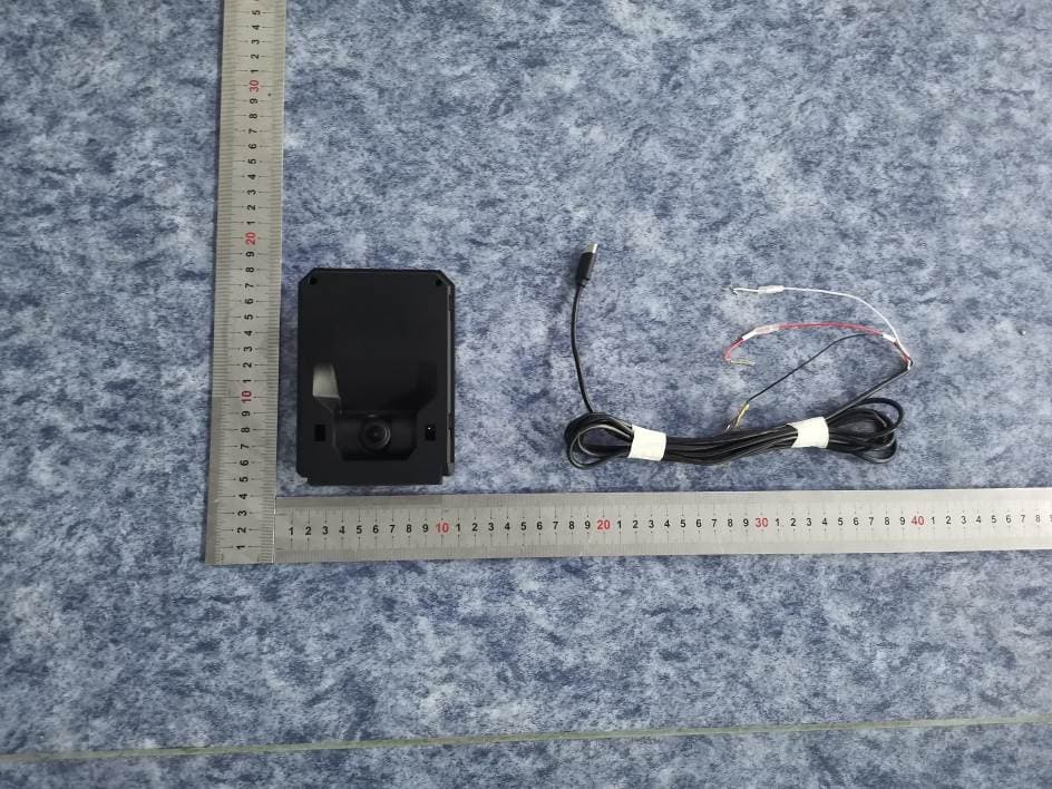
2AKAF-CAM17
Aug 21, 2024AI Recorder I
Equipment Class
DTS - Digital Transmission System
2AKAF-MDM01
Jul 16, 2024LTE CAT.1 Module
Equipment Class
PCB - PCS Licensed Transmitter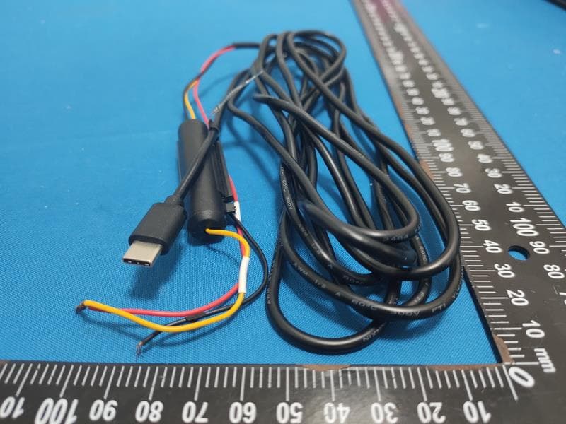
2AKAF-DOC01
Feb 17, 20224G Dock
Equipment Class
PCB - PCS Licensed Transmitter
2AKAF-TW06C2
Mar 11, 2021Secure 4K
Equipment Class
DSS - Part 15 Spread Spectrum Transmitter