2AKAF-TW06C2Secure 4K
Waylens Inc.
Click to zoom
Application Details
- Equipment Class
- DSS - Part 15 Spread Spectrum Transmitter
- Date of Grant
- Mar 11, 2021
- Application Purpose
- Original Equipment
- Date of Application
- Mar 11, 2021
- Equipment Note
- Secure 4K
- Frequency Range
- 2402.00000000 - 2480.00000000
- Company
- Waylens Inc.
- Country
- United States
Documents & Files
Document Text
Text extracted from the exhibit documents filed with the FCC. Open a document above to read the original.
Users Manual
Connect your Secure 4K using this W iFi SSID and password, making sure to keep them in a safe place for future reference. © 2020 Waylens, Inc. All rights reserved. 4K Placement Guide Power Cord Installation Guide What’s included with the Secure4K Secure4K Camera & Dock Secure4K Mount Plate & Adhesive Please ensure the Secure4K and any necessary power components are secured and out of reach of passengers, especially young children and pets. 4K 12 Option A OBD-II Power Cord Option B Direct Wire Power Cord DMS Module (Optional) Power Cord Locker Tamper Tape Status LED mode Camera Mount Screw microSD Card Slot Remote Camera Cable Holder Reset Button USB Type-C Power Waylens Button Cabin Lumination Remote Camera Cable Socket SIM Card Slot Status LED Remote Camera Cable Holder Solid Green Solid Blue Solid red Blinks Blue Blinks Blue and Red Power On Idle Recording Firmware Updating Error Secure4K Overview Click x1 Click x3 Press for 2s Press for 4s Flip on WiFi On/Off Flip on WiFi Direct Mode Flip on Recording Restart the camera Using the Waylens Fleet App The Waylens Fleet App is the primary interface for the Secure4K, providing the fleet an easy way to install and maintain the camera. Access the Secure4K through the App: Installation Guide of Secure4K Preview the video of Secure4K Network Test Power Cord Test Secure4K Maintenance Do not use mobile devices to access the Secure4K while operating the vehicle. Park your vehicle in a safe location before accessing the App . 34 Logo LED Waylens Button Function The product contains a LTE Module FCC ID: SRQ-ME3630 Installing your Secure4K (two options - Direct Wire or OBD-II Power Cord) 1. Locate the OBD-II socket in your vehicle, the upper figure shows some popular places. 2. Insert the OBD-II plug into the OBD-II socket firmly. NOTE: The OBD-II connector fits only one way into the vehicle’s OBD-II socket, do not force the fit; observe correct orientation before applying force. 3. Route the wire with USB Type-C plug of the OBD-II Power Cord to the expected camera mounting location on the windshield. NOTE: Leave an extra few inches of cord length near the camera to insert the Type-C plug into the Secure4K Dock, and also to make mounting and dismounting the camera easier. 4. Secure any excess wire after the camera is mounted. Park the car in a safe and convenient place for the installation The OBD-II socket Option A OBD-II Power Cord Option B Direct Wire Power Cord 1. Install power in the vehicle 1. Turn off the engine and the accessory power. 2. Find the location and layout of your fuse box as well as the appropriate fuse type from the vehicle’s user manual. NOTE: a. Professional installation assistance at a qualified dealer is recommended, if you are not familiar with identifying fuses in a vehicle and installing power system related items. b. Please contact [email protected] for assistance with finding an approved dealer in your area if you are unsure of where to locate one yourself. 3. Connect the red ACC wire to a switched fuse: a. A switched fuse is used to monitor the accessory power such as cigarette lighter, car radio, etc. They will be switched off after you turn off the car. Identify them by referring to the vehicle user manual or consulting a qualified professional. b. Verify the fuse is a switched fuse by using a multimeter to track voltage within the circuit across ignitions ON and OFF positions. c. If confirmed as a switched power fuse, remove the identified switched fuse from the fuse panel. Use the fuse puller tool if available. d. Remove the sleeve from the end of the red ACC wire, and wrap the wire around one of the blades of the switched fuse. e. Reinsert the fuse back into the fuse panel carefully and firmly to ensure the wire remains secured to the fuse blade. 4. Connect the yellow BATT+ wire to a constant power fuse a. The constant power fuses are used to monitor constant power within a vehicle. They will not be switched off after you turn off the car. Identify them by referring to the vehicle manual or consulting a professional. 56 b. Verify the fuse is a constant fuse by a multimeter to track voltage within the circuit across ignitions ON and OFF positions. c. If confirmed as a constant power fuse, remove the identified constant fuse from the fuse panel. Use the fuse puller tool if available. d. Remove the sleeve from the end of the yellow BATT+ wire and wrap the wire around one of the blades of the Constant Power fuse. e. Reinsert the fuse back into the fuse panel carefully and firmly to ensure the wire remains secured to the fuse blade. 5. Connect the black GND wire to a chassis ground point, such as a bolt, that is directly touching a bare metal surface of the vehicle’s framework. 6. Route the wire with USB Type-C plug of the Direct Wire Power Cord to the expected camera mounting location on the windshield. NOTE: Leave an extra few inches of cord length near the camera to insert the Type-C plug into the Secure4K Dock, and also to make mounting and dismounting the camera easier. 7. Secure any excess wire after the camera is mounted. 1. Put the Type-C Power Cord into the Power Cord Locker. Remove the Locker’s gasket if necessary. 2. Remove the Locker’s tape paper. 3. Insert the Type-C plug into the camera Type-C socket. Push the Locker to ensure glued together with the camera dock. 4. Seal with Tamp Tape. 5. Turn on the engine, the status LED will illuminate blue and then turn red if a SD card is inserted. For optimal performance, please ensure the power cord is firmly and securely fitted into the USB Type-C Power Connection. 1. Open the Waylens Fleet App and follow the prompts to connect to the Secure4K camera. 2. If can’t find the Secure4K WiFi network, normally is a network with name as Waylens-xxxxx (DIRECT-Waylens-xxxxx if WiFi Direct is enabled), press Waylens Button to wake up the WiFi. 3. Locate the diagnostic feature in the profile page(Skip Login) or Maintenance(Maintainer Login). 4. After the diagnostic, view th…
Text truncated - open the document above for the full version.
Cover Letter(s)
Company: Waylens Inc. Add: 2711 Centerville Road - Suite 400, Wilmington, Delaware 19808, United States Tel: +14084975377 Fax: +14 084975377 E-mail: [email protected] FCC Confidential Authorization Date:2020-07-30 FEDERAL COMMUNICATIONS COMMISSIONS Authorization and Evaluation Division 74 35 Oakland Mills Road Columbia, MD 21046 Subject: Confidentiality Request regarding application for certification of FCC ID: 2AKAF-TW06C2 To: who m it may concern, In accord ance with Sections 0.457 and 0.459 of the Commission’s Rules, Waylens Inc. hereby requests long-term confidential treatment of information accompanying this application as outlined below: Block Diagram Schematics Operatio n Description The above materials contain proprietary and confidential information not customarily released to the public. The public disclosure of these materials provides unjustified benefits to its competitors in the market. Sincerely Yours, Sig nature: Typed or Printed Name: Ding Gang Title: CEO
External Photos
EXHIBIT A - EUT EXTERNAL PHOTOGRAPHS Accessories camera Accessories camera
Internal Photos
EXHIBIT B - EUT INTERNAL PHOTOGRAPHS WCDMA/LTE Antenna 2.4G WiFi & BT &BLE Antenna
RF Exposure Info
Bay Area Compliance Laboratories Corp. (Kunshan) Report No.: RSHF200730001-00B FCC Part 15.247 Page 10 of 70 FCC §1.1310 & §2.1091 –MAXIMUM PERMISSIBLE EXPOSURE (MPE) Applicable Standard According to subpart §2.1091 and subpart §1.1310, systems operating under the provisions of this section shall be operated in a manner that ensures that the public is not exposed to radio frequency energy level in excess of the Commission’s guidelines. Limits for Maximum Permissible Exposure (MPE) (§1.1310, §2.1091) (B) Limits for General Population/Uncontrolled Exposure Frequency Range (MHz) Electric Field Strength (V/m) Magnetic Field Strength (A/m) Power Density (mW/cm 2 ) Averaging Time (minutes) 0.3-1.34 614 1.63 *(100) 30 1.34-30 824/f 2.19/f *(180/f²) 30 30-300 27.5 0.073 0.2 30 300-1500 / / f/1500 30 1500-100,000 / / 1.0 30 f = frequency in MHz; * = Plane-wave equivalent power density; According to §1.1310 and §2.1091 RF exposure is calculated. Calculated Formulary: Predication of MPE limit at a given distance S = PG/4πR² = power density (in appropriate units, e.g. mW/cm 2 ); P = power input to the antenna (in appropriate units, e.g., mW); G = power gain of the antenna in the direction of interest relative to an isotropic radiator, the power gain factor, is normally numeric gain; R = distance to the center of radiation of the antenna (appropriate units, e.g., cm); Bay Area Compliance Laboratories Corp. (Kunshan) Report No.: RSHF200730001-00B FCC Part 15.247 Page 11 of 70 Calculated Data: Mode Frequency Range (MHz) Antenna Gain Tune-up Output Power Evaluation Distance (cm) Power Density (mW/cm 2 ) MPE Limit (mW/cm 2 ) (dBi) (numeric)(dBm)(mW) BT 2402-2480 1.5 1.41 7.50 5.62 20 0.0016 1.0 BLE 2402-2480 1.5 1.41 2.00 1.58 20 0.0004 1.0 802.11b 2412-2462 1.5 1.41 20.50112.20 20 0.0315 1.0 802.11g 1.5 1.41 17.5056.23 20 0.0158 1.0 802.11n-HT20 1.5 1.41 17.5056.23 20 0.0158 1.0 802.11n-HT40 2422-2452 1.5 1.41 17.0050.12 20 0.0141 1.0 WCDMA Band 2 1850~1910 4.8 3.02 23.00199.53 20 0.1199 1.0 WCDMA Band 5 824-849 3.5 2.24 23.50223.87 20 0.0997 0.55 LTE Band 2 1850~1910 4.8 3.02 22.50177.83 20 0.1068 1.0 LTE Band 4 1710~1755 4.8 3.02 22.00158.49 20 0.0952 1.0 LTE Band 5 824-849 3.5 2.24 23.50223.87 20 0.0997 0.55 LTE Band 12 699~716 3.5 2.24 23.50223.87 20 0.0997 0.47 LTE Band 17 704-716 3.5 2.24 23.00199.53 20 0.0889 0.47 Note: (1) The all tune-up output powers are declared by the Manufacturer. (2) The LTE module FCC ID: SRQ-ME3630, Date of Grant: 08/28/2017. (3) Wi-Fi / BLE /BT and LTE can transmit simultaneously; the worst condition is 802.11b of Wi-Fi and LTE Band 12 as below: =0.0315/1.0+0.0997/0.47=0.0315+0.2121=0.2436< 1.0 Result: The device meet FCC MPE at 20 cm distance.
Test Report
FCC PART 15.247 TEST REPORT For Waylens Inc. 2711 Centerville Road - Suite 400 , Wilmington, Delaware 19808, United States FCC ID: 2AKAF-TW06C2 Report Type: Original Report Product Type: Secure 4K Project Engineer: Chao Gao Re port Number: RSHF200730001-00B Re port Date: 2020-12-01 Reviewed B y: Oscar Ye EMC Manager Prepared By: Bay Area Compliance Laboratories Corp. (Kunshan) No.248 Chenghu Road, Kunshan, Jiangsu province, China Tel: +86-0512-86175000 Fax: +86-0512-88934268 www.baclcorp.com.cn Bay Area Compliance Laboratories Corp. (Kunshan) Report No.: RSHF200730001-00B FCC Part 15.247 Page 2 of 70 TABLE OF CONTENTS GENERAL INFORMATION ....................................................................................................................................... 4 PRODUCT DESCRIPTION FOR EQUIPMENT UNDER TEST (EUT) ..................................................................................... 4 OBJECTIVE ................................................................................................................................................................... 4 RELATED SUBMITTAL(S)/GRANT(S) ............................................................................................................................. 4 TEST METHODOLOGY .................................................................................................................................................. 5 MEASUREMENT UNCERTAINTY .................................................................................................................................... 5 TEST FACILITY ............................................................................................................................................................. 5 SYSTEM TEST CONFIGURATION .......................................................................................................................... 6 DESCRIPTION OF TEST CONFIGURATION ...................................................................................................................... 6 EUT EXERCISE SOFTWARE .......................................................................................................................................... 6 SPECIAL ACCESSORIES ................................................................................................................................................. 6 EQUIPMENT MODIFICATIONS ....................................................................................................................................... 6 SUPPORT EQUIPMENT LIST AND DETAILS .................................................................................................................... 6 EXTERNAL I/O CABLE .................................................................................................................................................. 6 BLOCK DIAGRAM OF TEST SETUP ................................................................................................................................ 7 SUMMARY OF TEST RESULTS ............................................................................................................................... 8 TEST EQUIPMENT LIST ........................................................................................................................................... 9 FCC §1.1310 & §2.1091 –MAXIMUM PERMISSIBLE EXPOSURE (MPE) ....................................................... 10 FCC §15.203 - ANTENNA REQUIREMENT ........................................................................................................... 12 APPLICABLE STANDARD ............................................................................................................................................ 12 ANTENNA CONNECTOR CONSTRUCTION .................................................................................................................... 12 FCC §15.205, §15.209 & §15.247(d) – RADIATED EMISSIONS ........................................................................... 13 APPLICABLE STANDARD ............................................................................................................................................ 13 EUT SETUP ................................................................................................................................................................ 13 EMI TEST RECEIVER SETUP ....................................................................................................................................... 14 TEST PROCEDURE ...................................................................................................................................................... 14 CORRECTED AMPLITUDE & MARGIN CALCULATION ................................................................................................. 14 TEST RESULTS SUMMARY .......................................................................................................................................... 14 TEST DATA ................................................................................................................................................................ 15 FCC §15.247(a) (1)-CHANNEL SEPARATION TEST ........................................................................................... 26 APPLICABLE STANDARD ............................................................................................................................................ 26 TEST PROCEDURE ...................................................................................................................................................... 26 TEST DATA ................................................................................................................................................................ 26 FCC §15.247(a) (1) – 20 dB EMISSION BANDWIDTH .......................................................................................... 32 APP…
Text truncated - open the document above for the full version.
Test Setup Photos
EXHIBIT C - TEST SETUP PHOTOGRAPHS Radiated Emissions (Below 1GHz) Radiated Emissions (1GHz-18GHz)
Contact Information
Applicant
Ding Gang(COO)
Test Firm
Bay Area Compliance Laboratories Corp. (Kunshan)Mr. John Chan
[email protected]+86 0512 86175000
Technical Specifications
| # | Rule Parts | Frequency Range | Power Output |
|---|---|---|---|
| 1 | 15C | 2.40 GHz - 2.48 GHz | 6.00 mW |
Other Applications from Waylens Inc.
2AKAF-CAM20
Jun 09, 2026AI Recorder 3 Pro
Equipment Class
NII - Unlicensed National Information Infrastructure TX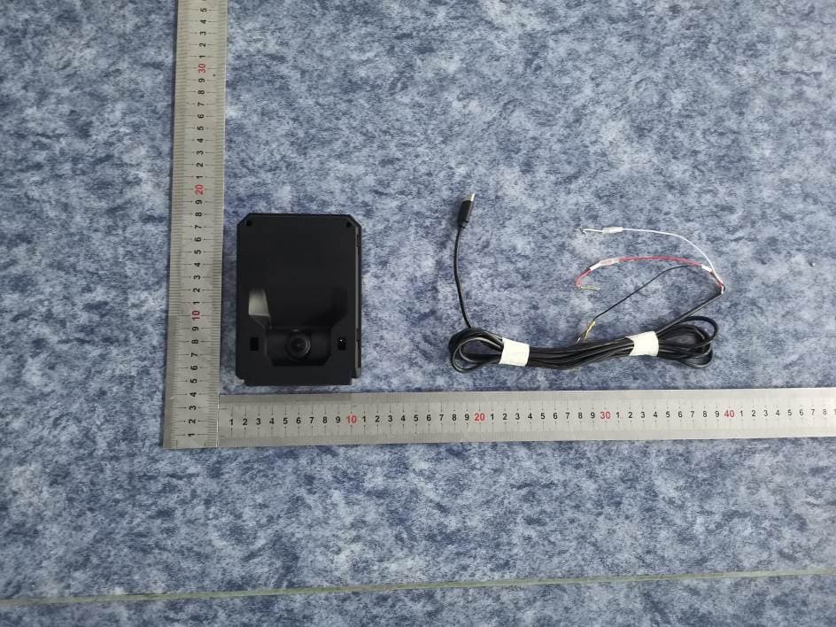
2AKAF-CAM17
Aug 21, 2024AI Recorder I
Equipment Class
DTS - Digital Transmission System
2AKAF-MDM01
Jul 16, 2024LTE CAT.1 Module
Equipment Class
PCB - PCS Licensed Transmitter
2AKAF-CAM12
Jul 12, 2023AI Recorder II
Equipment Class
DSS - Part 15 Spread Spectrum Transmitter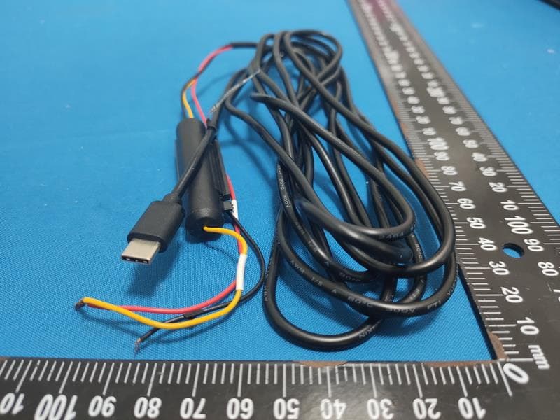
2AKAF-DOC01
Feb 17, 20224G Dock
Equipment Class
PCB - PCS Licensed Transmitter