2AKUO-RN02smart ring
Shenzhen Smart Care Technology LimitedApplication Details
- Equipment Class
- DSS - Part 15 Spread Spectrum Transmitter
- Date of Grant
- Jun 08, 2026
- Application Purpose
- Original Equipment
- Equipment Note
- smart ring
- Frequency Range
- 2402.00000000 - 2480.00000000
- Country
- China
Documents & Files
Document Text
Text extracted from the exhibit documents filed with the FCC. Open a document above to read the original.
ID Label/Location Info
FCC ID LABEL: Ca. 10mm x 5mm Label Location FCC ID: 2AKUO-RN02
RF Exposure Info
FCC RF Exposure EUT Description: smart ring Model No.: RN02 FCC ID: 2AKUO-RN02 1. L imits According to KDB 447498 D01 General RF Exposure Guidance v06 The 1‐g and 10‐g SAR test exclusion thresholds for 100 MHz to 6 GHz at test separation distances ≤50 mm are determined by: [(max power of channel, including tune‐up tolerance, mW)/(min. test separation distance, mm)]ꞏ[√f(GHz)]≤3.0 for 1‐g SAR and ≤ 7.5 for 10‐g extremity SAR, Where: Result=P/D*√F F= the RF channel transmit frequency in GHz P=Maximum turn‐up power in mw D=Min. test separation distance in mm 2. Test Result of RF Expos ure Evaluation Frequency (MHz) Output power (dBm) Tune Up Power (dBm) Max Tune Up power (mW) Min test separati on distance mm Result Limit SAR Test Exclusion 2402 4.27 4±1(5) 3.162 5 0.980 3.0 Pass 2402 4.30 4±1(5) 3.162 5 0.980 3.0 Pass Note: PK Output power= conducted power. Conducted power see the test report HK2605060485-1E/2E, antenna gain=-11.7dBi Per KDB 447498 D01, when the minimum test separation distance is < 5 mm, a distance of 5 mm is applied to determine SAR test exclusion. The test exclusion threshold is 0.980 which is<= 3, SAR testing is not required. Note: Exclusion Thresholds Results=[(max. power of channel, including tune-up tolerance, mW)/(min. test separation distance, mm)] ꞏ[√f(GHz)] f(GHz) is the RF channel transmit frequency in GHz Distance=5mm
Test Report
Page 1 of 45 Report No.: HK2605060485-2E FCC Test Report Test Report On Behalf of Shenzhen Smart Care Technology Limited For smart ring Model No.: RN02, RN01, RN03, RN04, RN05, RN06, RN07 FCC ID: 2AKUO-RN02 Prepared For: Shenzhen Smart Care Technology Limited The 6rd Floor,Block 2, An’da Industrial Park, Heping Road,Heping Community, Fuhai Street, Bao’an District, Shenzhen, 518000, China Prepared By: Shenzhen HUAK Testing Technology Co., Ltd. 1-2/F., Building B2, Junfeng Zhongcheng Zhizao Innovation Park, Heping, Fuhai Street, Bao’an District, Shenzhen, Guangdong, China Date of Test: May 06, 2026 ~ May 15, 2026 Date of Report: May 15, 2026 Report Number: HK2605060485-2E Page 2 of 45 Report No.: HK2605060485-2E Test Result Certification Applicant’s Name .................. : Shenzhen Smart Care Technology Limited Address .................................. : The 6rd Floor,Block 2, An’da Industrial Park, Heping Road,Heping Community, Fuhai Street, Bao’an District, Shenzhen, 518000, China Manufacturer's Name ........... : Shenzhen Smart Care Technology Limited Address .................................. : The 6rd Floor,Block 2, An’da Industrial Park, Heping Road,Heping Community, Fuhai Street, Bao’an District, Shenzhen, 518000, China Product Description Trade Mark ............................. : AURAFIT Product Name ......................... : smart ring Model and/or Type Reference : RN02, RN01, RN03, RN04, RN05, RN06, RN07 Standards .............................. : 47 CFR FCC Part 15 Subpart C 15.247 This publication may be reproduced in whole or in part for non-commercial purposes as long as the Shenzhen HUAK Testing Technology Co., Ltd. is acknowledged as copyright owner and source of the material. Shenzhen HUAK Testing Technology Co., Ltd. takes no responsibility for and will not assume liability for damages resulting from the reader's interpretation of the reproduced material due to its placement and context. Date of Test ............................................ : Date (s) of Performance of Tests ............ : May 06, 2026 ~ May 15, 2026 Date of Issue ........................................... : May 15, 2026 Test Result ............................................... : Pass Testing Engineer Len Liao Technical Manager Sliver Wan Authorized Signatory Jason Zhou Page 3 of 45 Report No.: HK2605060485-2E Table of Contents Page 1. Summary ................................................................................................... 5 1.1. Test Standards ............................................................................................................ 5 1.2. Test Procedures and Results ...................................................................................... 5 1.3. Information of the Test Laboratory .............................................................................. 6 1.4. Statement of the Measurement Uncertainty ................................................................ 6 2. General Information ................................................................................. 7 2.1. Environmental Conditions ........................................................................................... 7 2.2. General Description of EUT ........................................................................................ 7 2.3. Description of Test Modes and Test Frequency .......................................................... 8 2.4. Equipments Used during the Test ............................................................................... 9 2.5. Related Submittal(s) / Grant (s) ................................................................................ 10 2.6. Modifications ............................................................................................................. 10 2.7. Description of Test Setup .......................................................................................... 10 2.8. Description of Support Units ..................................................................................... 11 3. Test Conditions and Results ................................................................. 12 3.1. AC Conducted Emissions Test .................................................................................. 12 3.2. Radiated Emissions .................................................................................................. 15 3.3. Maximum Peak Conducted Output Power ................................................................ 23 3.4. 20dB Bandwidth ........................................................................................................ 24 3.5. Frequency Separation .............................................................................................. 27 3.6. Number of Hopping Frequency ................................................................................. 29 3.7. Time of Occupancy (Dwell Time) .............................................................................. 31 3.8. Out-of-Band Emissions ............................................................................................. 34 3.9. Pseudorandom Frequency Hopping Sequence ........................................................ 41 3.10. Antenna Requirement ........................................................................................... 42 4. Test Setup Photos of the EUT ............................................................... 43 5. Photos of the EUT .................................................................................. 45 Page 4 of 45 Report No.: HK2605060485-2E ** Issued History ** Revision Description Issued Date Remark Revision 1.0 Initial Test Report Release May 15, 2026 Jason Zhou Page 5 of 45 Report No.: HK2605060485-2E 1. Summary 1.1. Test Standards The tests were performed according to following standards: FCC Rules Part 15.247: Frequency Hopping, Direct Spread Spectrum and Hybrid Systems that are in operation within the bands of 902-928 MHz, 2400-2483.…
Text truncated - open the document above for the full version.
Test Report
Page 27 of 45 Report No.: HK2605060485-2E 3.5. Frequency Separation Limit Frequency hopping systems shall have hopping channel carrier frequencies separated by minimum of 25 KHz or the 2/3*20dB bandwidth of the hopping channel, whichever is greater. Test Procedure The transmitter output was connected to the spectrum analyzer through an attenuator. The bandwidth of the fundamental frequency was measured by spectrum analyzer with 300 KHz RBW and 1000 KHz VBW. Test Configuration EUT SPECTRUM ANALYZER Test Results Modulation Channel Channel Separation (MHz) Limit(MHz) Result GFSK CH39 1.002 0.634 Pass CH40 π/4DQPSK CH39 1.004 0.856 Pass CH40 Note: We have tested all mode at high, middle and low channel, and recorded worst case at middle Test plot as follows: Page 28 of 45 Report No.: HK2605060485-2E Frequency Separation GFSK π/4DQPSK Page 29 of 45 Report No.: HK2605060485-2E 3.6. Number of Hopping Frequency Limit Frequency hopping systems in the 2400–2483.5 MHz band shall use at least 15 channels. Test Procedure The transmitter output was connected to the spectrum analyzer through an attenuator. Set spectrum analyzer start 2400MHz to 2483.5MHz. Test Configuration EUT SPECTRUM ANALYZER Test Results Modulation Number of Hopping Channel Limit Result GFSK 79 ≥15 Pass π/4DQPSK 79 Test plot as follows: Page 30 of 45 Report No.: HK2605060485-2E GFSK Modulation π/4DQPSK Modulation Page 31 of 45 Report No.: HK2605060485-2E 3.7. Time of Occupancy (Dwell Time) Limit The average time of occupancy on any channel shall not be greater than 0.4 seconds within a period of 0.4 seconds multiplied by the number of hopping channels employed. Test Procedure The transmitter output was connected to the spectrum analyzer through an attenuator. Set center frequency of spectrum analyzer=operating frequency with 1MHz RBW and 3MHz VBW, Span 0Hz. Test Configuration EUT SPECTRUM ANALYZER Test Results Modulation Packet Pulse time (ms) Number of transmission in 31.6s (79 Hopping*0.4) = Burst Count Dwell time (second) Limit (second) Result GFSK DH1 0.383 31 (pulses) * 10 = 310 0.119 0.40 Pass DH3 1.639 16 (pulses) * 10 = 160 0.262 DH5 2.887 13 (pulses) * 10 = 130 0.375 π/4DQPSK 2-DH1 0.394 32 (pulses) * 10 = 320 0.126 0.40 Pass 2-DH3 1.645 15 (pulses) * 10 = 150 0.247 2-DH5 2.893 12 (pulses) * 10 = 120 0.347 Note: 1. We have tested all mode at high,middle and low channel,and recoreded worst case at middle channel. 2. Dwell time = [Pulse time (ms) / 1000] × Burst Count Test plot as follows: Page 32 of 45 Report No.: HK2605060485-2E GFSK Modulation DH1 DH3 DH5 Page 33 of 45 Report No.: HK2605060485-2E π/4DQPSK Modulation 2-DH1 2-DH3 2-DH5 Page 34 of 45 Report No.: HK2605060485-2E 3.8. Out-of-Band Emissions Limit In any 100 kHz bandwidth outside the frequency band in which the spread spectrum or digitally modulated intentional radiator is operating, the radio frequency power that is produced by the intentional radiator shall be at least 20 dB below that in the 100 kHz bandwidth within the band that contains the highest level of the desired power, based on either an RF con-ducted or a radiated measurement, pro-vided the transmitter demonstrates compliance with the peak conducted power limits. If the transmitter com-plies with the conducted power limits based on the use of RMS averaging over a time interval, as permitted under paragraph (b)(3) of this section, the attenuation required under this paragraph shall be 30 dB instead of 20 dB. Attenuation below the general limits specified in §15.209(a) is not required. Test Procedure Connect the transmitter output to spectrum analyzer using a low loss RF cable, and set the spectrum analyzer to RBW=100 kHz, VBW= 300 kHz, peak detector , and max hold. Measurements utilizing these setting are made of the in-band reference level, band edge and out-of-band emissions. Test Configuration EUT SPECTRUM ANALYZER Test Results Remark: The measurement frequency range is from 30MHz to the 10th harmonic of the fundamental frequency. The lowest, middle and highest channels are tested to verify the spurious emissions and bandage measurement data. We measured all conditions (DH1, DH3, DH5) and recorded worst case at DH5 and 2DH5 Test plot as follows: Page 35 of 45 Report No.: HK2605060485-2E GFSK CH00 CH39 Page 36 of 45 Report No.: HK2605060485-2E CH78 Page 37 of 45 Report No.: HK2605060485-2E Left Band edge hoping off Right Band edge hoping off Left Band edge hoping on Right Band edge hoping on Page 38 of 45 Report No.: HK2605060485-2E π/4DQPSK CH00 CH39 Page 39 of 45 Report No.: HK2605060485-2E CH78 Page 40 of 45 Report No.: HK2605060485-2E Left Band edge hoping off Right Band edge hoping off Left Band edge hoping on Right Band edge hoping on Page 41 of 45 Report No.: HK2605060485-2E 3.9. Pseudorandom Frequency Hopping Sequence Test Applicable For 47 CFR Part 15C section 15.247 (a) (1): Frequency hopping systems shall have hopping channel carrier frequencies separated by a minimum of 25 kHz or the 20 dB bandwidth of the hop-ping channel, whichever is greater. Alternatively, frequency hopping systems operating in the 2400–2483.5 MHz band may have hopping channel carrier frequencies that are separated by 25 kHz or two-thirds of the 20 dB bandwidth of the hopping channel, whichever is greater, provided the systems operate with an output power no greater than 125 mW. The system shall hop to channel frequencies that are selected at the system hopping rate from a pseudo randomly ordered list of hopping frequencies. Each frequency must be used equally on the average by each transmitter. The system receivers shall have input bandwidths that match the hop-ping channel bandwidths of their corresponding transmitters and shall shift frequencies in synchronization with the transmitted signals. EUT Pseudorandom Frequency Hopping Sequence Requirement The pseudorandom frequency hopping sequence may be generated in a nice-stage shift register whose 5 th and 9 th stage outputs are added in a modulo-two addition stage.…
Text truncated - open the document above for the full version.
Test Report
Project:RN02 Author: Haiou.Zhu File Name: RN02_APP_A.doc Date: 2026-3-18 Revision: A CONFIDENTIAL Shenzhen OnePlusOne Wireless Communication Technology Co.,Ltd. Page 1 of 6 深圳市一加一无线通讯技术有限公司 7th Floor, Building B1, Hangcheng Jinchi Industrial Park, Hangcheng Street, Baoan District, Shenzhen City. 承认书 APPROVAL SHEET 客户 Customer 爱保护 项目名 Project RN02 BT Antennas 料号 Part NO. 规格 Specification BT Antennas Project:RN02 Author: Haiou.Zhu File Name: RN02_APP_A.doc Date: 2026-3-18 Revision: A CONFIDENTIAL Shenzhen OnePlusOne Wireless Communication Technology Co.,Ltd. Page 3 of 6 1 Antenna description It summarize BT antennas for project RN02 .BT antenna’s frequency band is 2400-2500MHz. BTantenna’s type is 单级 1.1 Part number Part number of antenna: RN02 BT Antennas 2 Electrical Performance 2.1 Specification BT Frequency Range 2400MHz~2500MHz <-5 >15% Return Loss Efficiency 2.2 Measurement Set-up 2.2.1 VSWR and Return Loss VSWR measurements (S 11 ) were performed using an Agilent ENA series Network Analyzer and the previously described test fixture. Coaxial chokes were used to mitigate surface currents on the outside of the cabling. The testing was performed in free space. 2.2.2 Efficiency and Gain The gain of the antenna was measured in OPO’s 3D anechoic chamber in Shenzhen, China. The chamber is a ETS system capable of doing tests from 380MHz to 6GHz. Coaxial chokes on the feed cable were used to mitigate surface currents during passive tests. The measurement results are calibrated using dipole standards. For TRP and TIS the chamber uses a 8960 / MT8820C to establish the connection with the mobile device and read the power. 3 Reference measurement data 3.1 Passive Project:RN02 Author: Haiou.Zhu File Name: RN02_APP_A.doc Date: 2026-3-18 Revision: A CONFIDENTIAL Shenzhen OnePlusOne Wireless Communication Technology Co.,Ltd. Page 4 of 6 Return SWR 3.2 Active Project:RN02 Author: Haiou.Zhu File Name: RN02_APP_A.doc Date: 2026-3-18 Revision: A CONFIDENTIAL Shenzhen OnePlusOne Wireless Communication Technology Co.,Ltd. Page 5 of 6 BT 4 Mechanical description 4.1 Drawings Project:RN02 Author: Haiou.Zhu File Name: RN02_APP_A.doc Date: 2026-3-18 Revision: A CONFIDENTIAL Shenzhen OnePlusOne Wireless Communication Technology Co.,Ltd. Page 6 of 6
Test Setup Photos
Test Model: RN02 Radiated Emission AC Conducted Emission RF Conducted Emission
Contact Information
Applicant
Helen Huang
[email protected]Fax: +86-755-25737350
Technical Contact
KIIGOO.HOT INCEthan Liao
17890 CASTLETON STREET, SUITE 107 · CITY OF INDUSTRY, California, 91748 · United States
Test Firm
Shenzhen HUAK Testing Technology Co., Ltd.Jason Zhou
Technical Specifications
| # | Rule Parts | Frequency Range | Power Output |
|---|---|---|---|
| 1 | 15C | 2.40 GHz - 2.48 GHz | 2.69 mW |
Other Applications from Shenzhen Smart Care Technology Limited
2AKUO-FW5
Aug 18, 2026Earbud
Equipment Class
DSS - Part 15 Spread Spectrum Transmitter2AKUO-GJ03A
Jan 09, 2026Smart glasses
Equipment Class
DTS - Digital Transmission System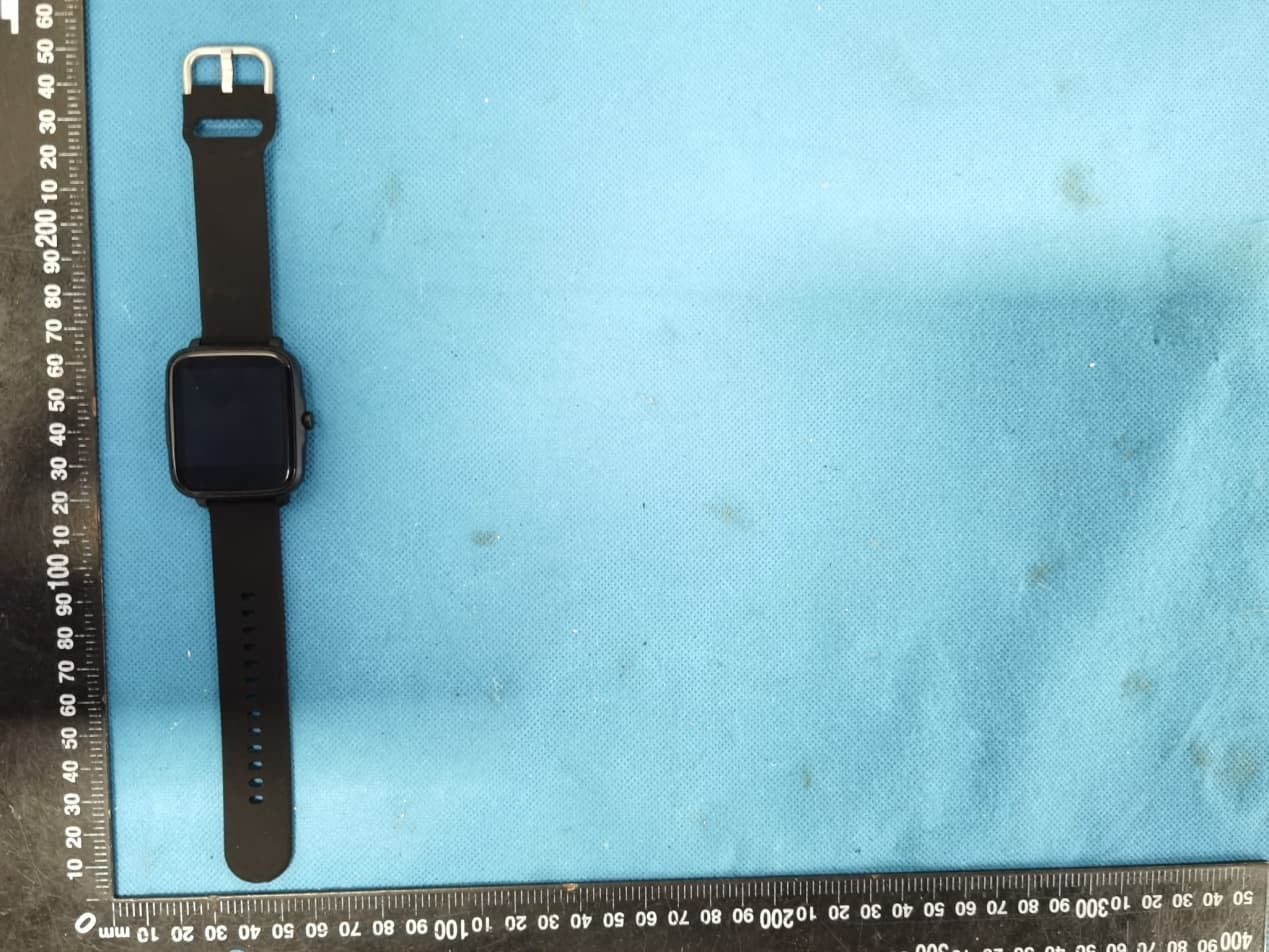
2AKUO-IML
May 25, 2021Smart watch
Equipment Class
DTS - Digital Transmission System