2ALB3LH475DGDECT 6.0 Dongle
IPN Headsets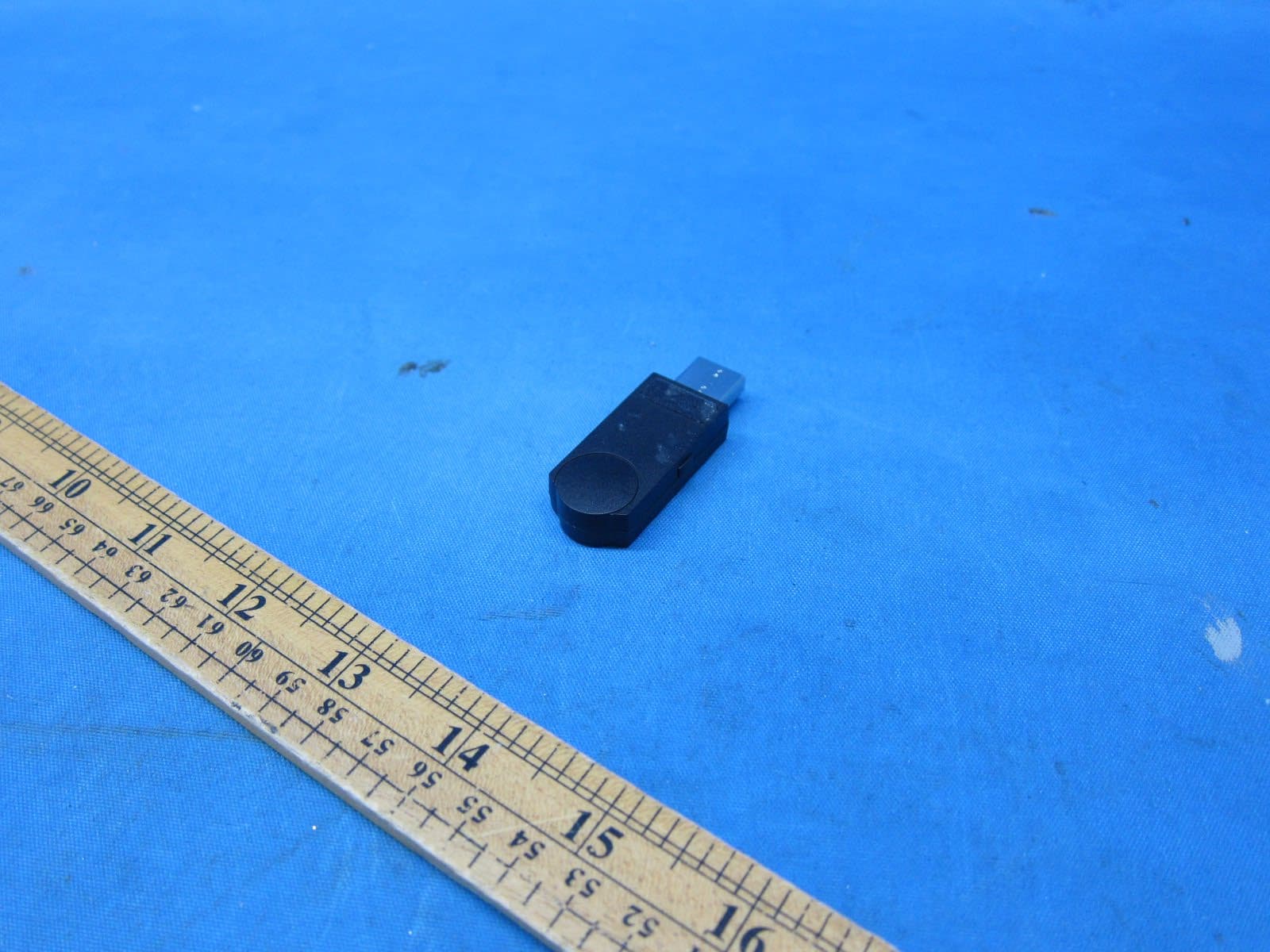
Click to zoom
Application Details
- Equipment Class
- PUB - Part 15 Unlicensed PCS Base Station
- Date of Grant
- Feb 27, 2023
- Application Purpose
- Original Equipment
- Date of Application
- Feb 27, 2023
- Equipment Note
- DECT 6.0 Dongle
- Frequency Range
- 1921.53600000 - 1928.44800000
- Company
- IPN Headsets
- Country
- Netherlands
Documents & Files
Document Text
Text extracted from the exhibit documents filed with the FCC. Open a document above to read the original.
Users Manual
ŸIncrease the separation between the equipment and receiver ŸConnect the equipment into an outlet on a circuit different from that to which the receiver is connected The USB cable(s) included in this package must be used with this product to ensure compliance with the Class B FCC limits. The USB port on base station is for data transfer only without charging function. RF Radiation Exposure ŸConsult the dealer or an experienced radio/TV technician for help This product compliances with FCC RF radiation exposure limits set forth for an uncontrolled environment. For Base unit: Caution: To maintain the compliance with FCC’s RF exposure guidance, place the Base unit at least 20cm from nearby persons. Power adaptor model: ZHT061U-0850500 (CHNHT INTERNATIONAL (HK) CO LIMITED) Battery model: 402035 (OI NAN TECHNOLOGY LTD) ŸRisk of explosion if battery is replaced by incorrect type disposed of used batteries according to the instruction. ŸBattery cannot be subjected to high or low extreme temperatures, low air pressure at high altitude during use, storage or transportation. ŸReplacement of a battery with an incorrect type that can result in an explosion or the leakage of flammable liquid or gas. ŸDisposal of a battery into fire or a hot oven, or mechanically crushing or cutting of a battery, that can result in an explosion. CAUTION Safety Instruction ŸLeaving a battery in an extremely high temperature surrounding environment that can result in an explosion or the leakage of flammable liquid or gas. ŸA battery subjected to extremely low air pressure that may result in an explosion or the leakage of flammable liquid or gas. ŸUse only power supplies and rechargeable battery listed in below. ŸThe applied nameplate is located at the bottom of the product’s base. This device complies with Part 15 of the FCC Rules. Operation is subject to the following two conditions: (1) this device may not cause harmful interference, and (2) this device must accept any interference received, including interference that may cause undesired operation. Warning: Changes or modifications to this unit not expressly approved by the party responsible for compliance could void the user’s authority to operate the equipment. ŸOperating, charging and storage temperatures are 32 ̊F to 104 ̊F (0 ̊C to 40 ̊C) ŸFor PLUGGABLE EQUIPMENT, the socket-outlet shall be installed near the equipment and shall be easily accessible ŸNOTE: This equipment has been tested and found to comply with the limits for a Class B digital device, pursant to Part 15 of the FCC Rules. These limits are designed to provide reasonable protection against harmful interference in a residential installtion. This equipment generates, uses and can radiate radio frequency energy and, if not installed and used in accordance with the instructions, may cause harmful interference to radio communications. However, there is no guarantee that interference will not occur in a particular installation. If this equipment does cause harmful interference to radio or television reception, which can be determined by turning the equipment off and on, the user is encouraged to try to correct the interference by one or more of the following measures: ŸReorient or relocate the receiving antenna Should you experience troubles with this equipment in the US, please contact: Headsets.com Inc 1. This device may not cause interference This Class B digital apparatus complies with Canadian requirements CAN ICES-003(B)/NMB-003 (B) 1854 Air Lane Drive, Unit 6 This device contains licence-exempt transmitter(s)receiver(s) that comply with Innovation, Science and Economic Development Canada’s licence-exempt RSS(s). Operation is subject to the following two conditions: Industry Canada 2. This device must accept any interference, including interference that may cause undesired operation of the device. Nashville, Tn37210 USA Tel: 1-800-432-3738 ŸLaisser une batterie à des températures très élevées peut provoquer une explosion ou une fuite de liquide ou de gaz inflammable. ŸLa mise au rebut d'une batterie dans un feu ou un four chaud, ou l'écrasement ou la découpe d'une batterie, peut entraîner une explosion. Adaptateur secteur modele: ZHT061U-0850500 (CHNHT INTERNATIONAL (HK) CO LIMITED) Modele de batterie: 402035 (OI NAN TECHNOLOGY LTD) ŸPour l'équipement à brancher, la prise doit être proche de l'équipement et facile d'accès. ŸMettre au rebut les batteries usagées conformément aux réglementations locales. ŸLa plaque signalétique se trouve en bas de la base du produit. ŸUtilisez uniquement les alimentations et la batterie rechargeable énumérées ci-dessous. PRÉCAUTION ŸUne batterie sous très faible pression d'air peut causer une explosion ou une fuite de liquide ou de gaz inflammable. ŸLes températures de fonctionnement, de charge et d’entreposage sont de 0 °C à 40 °C (32 °F à 104 °F) L'émetteur/récepteur exempt de licence contenu dans le présent appareil est conforme aux CNR d'Innovation, Sciences et Développement économique Canada applicables aux appareils radio exempts de licence. L'exploitation est autorisée aux deux conditions suivantes : (1) L'appareil ne doit pas produire de brouillage; CAN ICES-003 (B) / NMB-003 (B) ŸATTENTION: Remplacer une batterie par une batterie incorrecte peut provoquer une explosion ou une fuite de liquide ou de gaz inflammable. ŸLa batterie ne doit pas être soumise à des températures extrêmement élevées ou basses ou à une basse pression atmosphérique à haute altitude pendant son utilisation, son entreposage ou son transport. Instructions de Sécurité (2) L'appareil doit accepter tout brouillage radioélectrique subi, même si le brouillage est susceptible d'en compromettre le fonctionnement.
Attestation Statements
2/22/2023
External Photos
INTERTEK TESTING SERVICES External Photos FCC ID: 2ALB3LH475DG IC: 23665-DG001
ID Label/Location Info
CM US C Intertek 5008497 A/V C.I. T.E. CM US C Intertek 5008497 A/V C.I. T.E. CM US C Intertek 5008497 A/V C.I. T.E. IC: 23665-DG001 HVIN:475DIC: 23665-DG001 HVIN: 475DIC: 23665-DG001 HVIN: 470D MODEL: LH475DGModel: LH475DGModel: LH470DG FCC ID: 2ALB3LH475DGFCC ID: 2ALB3LH475DGFCC ID: 2ALB3LH475DG Made in ChinaMade in ChinaMade in China Label of LH475 Label dimension: 23 x 16.5mm Label of LH470
Internal Photos
INTERTEK TESTING SERVICES Internal Photos FCC ID: 2ALB3LH475DG IC: 23665-DG001 INTERTEK TESTING SERVICES Internal Photos FCC ID: 2ALB3LH475DG IC: 23665-DG001 INTERTEK TESTING SERVICES Internal Photos FCC ID: 2ALB3LH475DG IC: 23665-DG001
RF Exposure Info
INTERTEK TESTING SERVICES FCC ID: 2ALB3LH475DG RF exposure - 1 of 1 For Standalone SAR test exclusion consideration, when the corresponding SAR Exclusion Threshold requirement in KDB 447498 is satisfied, standalone SAR evaluation for general population exposure conditions, by measurement or numerical simulation is not required. Description the tested model: LH475DG EUT Description : 1.9GHz DECT 6.0 Dongle Model : LH475DG Operating Configuration(s) : Body Operating mode (s) : Voice call Device Category : Portable Device Tx Frequency : 1921.536 – 1928.448 MHz Production tolerance : 10 dBm (Minimum) to 18.6 dBm (Maximum) Antenna gain : 0.47 dBi = 1.11 (num gain) Maximum source-based time- averaging duty factor : 8.3% = (2/24 x100%) Minimum separation distance : 5 mm Applicable FCC KDB : FCC KDB 447498 D01v06 FCC KDB 865664 D02v01r02 From above data, the source-based time-averaging output power is as follow: The Maximum Conducted Power = 18.6 dBm = 72.4 mW The Maximum conducted Power source-based time-averaging output power = (72.4 * 0.083) mW = 6.01 mW In the frequency range of 100MHz to 6GHz and test separation distance ≤ 50mm, the SAR Exclusion Threshold will be determined as follow, The SAR exclusion threshold = () )(/0.3GHzFTD× = 10.80 mW where TD = 5 mm and F(GHz) = 1.928 GHz Conclusion Since the calculated conducted source-based time-averaged output power is 6.01 mW, which is less than the SAR Exclusion Threshold at 5mm test separation distance 10.80 mW for general population and uncontrolled exposure, standalone SAR evaluation for general population exposure conditions, by measurement or numerical simulation is not required.
Test Report
TEST REPORT 2/F., Garment Centre, 576 Castle Peak Road, Kowloon, Hong Kong SAR, China. Telephone: (852) 2173 8888 Facsimile: (852) 2785 5487 www.intertek.com Intertek’s standard Terms and Conditions can be obtained at our website http://www.intertek.com/terms/. The test report only allows to be revised within the retention period unless further standard or the requirement was noticed. This report is for the exclusive use of Intertek's Client and is provided pursuant to the agreement between Intertek and its Client. Intertek's responsibility and liability are limited to the terms and conditions of the agreement. Intertek assumes no liability to any party, other than to the Client in accordance with the agreement, for any loss, expense or damage occasioned by the use of this report. Only the Client is authorized to permit copying or distribution of this report and then only in its entirety. Any use of the Intertek name or one of its marks for the sale or advertisement of the tested material, product or service must first be approved in writing by Intertek. The observations and test results in this report are relevant only to the sample tested. This report by itself does not imply that the material, product, or service is or has ever been under an Intertek certification program. © 2017 Intertek Page 1 of 52 Report Number: 22080932HKG-009 Application For Original Grant of 47 CFR Part 15 Certification Unlicensed Personal Communication Service Devices / 2 GHz License-exempt Personal Communications Service Devices (Dongle) FCC ID: 2ALB3LH475DG Prepared and Checked by: Approved by: Signed on File Leung Chiu Kuen, Stanley Engineer Lee Shui Tim, Tim Assistant Manager Date: February 9, 2023 TEST REPORT IPN Headsets Intertek Report No: 22080932HKG-009 Page 2 of 52 GENERAL INFORMATION Grantee: IPN Headsets Grantee Address: Bijsterhuizen 2414, 6604 LL Wijchen, The Netherlands. FCC Specification Standard: FCC Part 15, October 1, 2021 Edition FCC ID: 2ALB3LH475DG FCC Model(s): LH475DG, LH470DG, LH47XDG Type of EUT: Unlicensed Personal Communications Service Devices Description of EUT: DECT 6.0 Dongle Serial Number: N/A Sample Receipt Date: August 23, 2022 Date of Test: August 23, 2022 to October 11, 2022 Report Date: February 9, 2023 Environmental Conditions: Temperature: +10 to 40°C Relative Humidity: 10 to 90% Conclusion: Test was conducted by client submitted sample. The submitted sample as received complied with the 47 CFR Part 15 Certification. TEST REPORT IPN Headsets Intertek Report No: 22080932HKG-009 Page 3 of 52 TABLE OF CONTENTS 1.0 TEST RESULTS SUMMARY & STATEMENT OF COMPLIANCE .......................................... 4 1.1 Summary of Test Results ........................................................................................... 4 1.2 Statement of Compliance ......................................................................................... 5 2.0 GENERAL DESCRIPTION ................................................................................................ 6 2.1 Product Description .................................................................................................. 6 2.2 Technical Description ................................................................................................ 6 2.3 Test Methodology ..................................................................................................... 6 2.4 Test Facility ................................................................................................................ 6 3.0 SYSTEM TEST CONFIGURATION .................................................................................... 7 3.1 Justification ............................................................................................................... 7 3.2 Radiated Emission Test Setup ................................................................................... 8 3.3 AC Line Conducted Emission Test Setup ................................................................... 9 3.4 Conducted Emission Test Configuration ................................................................... 9 3.5 Conducted Monitoring and Operational Test Configuration ................................. 10 3.6 EUT Exercising Software.......................................................................................... 10 3.7 Details of EUT and Description of Accessories ....................................................... 11 3.8 Measurement Uncertainty...................................................................................... 11 4.0 MEASUREMENT RESULTS ........................................................................................... 12 4.1 Antenna Requirement ............................................................................................. 12 4.2 Digital Modulation Techniques ............................................................................... 12 4.3 Emission Bandwidth ................................................................................................ 12 4.4 Directional Gain of the Antenna ............................................................................. 14 4.5 Peak Transmit Power .............................................................................................. 15 4.6 Power Spectral Density ........................................................................................... 17 4.7 Automatic Discontinuation of Transmission ........................................................... 19 4.8 Unwanted Emission Inside the Sub-Band ............................................................... 20 4.9 Emissions Outside the Sub-Band ............................................................................ 23 4.10 AC Power Line Conducted Emissions ...................................................................... 30 4.11 Frame Repetition Stability ...................................................................................... 34 4.12 Frame Perio…
Text truncated - open the document above for the full version.
Test Report
NOTE:ThisdocumentisissuedbyShenzhenMorlabCommunicationsTechnologyCo.,Ltd.,thetestreportshallnotbereproducedexceptin fullwithoutpriorwrittenpermissionofthecompany.Thetestresultsapplyonlytotheparticularsample(s)testedandtothespecifictestscarried outwhichisavailableonrequestforvalidationandinformationconfirmedatourwebsite. MORLAB SHENZHENMORLABCOMMUNICATIONSTECHNOLOGYCo.,Ltd. FL1-3,BuildingA,FeiYangSciencePark,No.8LongChangRoad, Block67,BaoAnDistrict,ShenZhen,GuangDongProvince,P.R.China Tel:86-755-36698555Fax:86-755-36698525 Http://www.morlab.cnE-mail:[email protected] Page1of 12 REPORTNo.:SZ22100215E01 TESTREPORT APPLICANT:OrchidElectronicsLimited PRODUCTNAME:DECTDongleAntenna MODELNAME:OEL_ANT_005 TRADENAME:N/A BRANDNAME:N/A STANDARD(S):IEEEStd149-2021 RECEIPTDATE:2022-10-24 TESTDATE:2022-10-26 ISSUEDATE:2022-12-27 Editedby: : FangJinshan(Rapporteur) Approvedby: : ChiShide(Supervisor) Testedby MORLAB SHENZHENMORLABCOMMUNICATIONSTECHNOLOGYCo.,Ltd. FL1-3,BuildingA,FeiYangSciencePark,No.8LongChangRoad, Block67,BaoAnDistrict,ShenZhen,GuangDongProvince,P.R.China Tel:86-755-36698555Fax:86-755-36698525 Http://www.morlab.cnE-mail:[email protected] Page2of12 REPORTNo.:SZ22100215E01 DIRECTORY 1.TechnicalInformation ........................................................................................................3 1.1.ApplicantandManufacturerInformation ....................................................................3 1.2.EquipmentUnderTest(EUT)Description...................................................................3 2.TestResults........................................................................................................................4 2.1.AppliedReferenceDocuments.....................................................................................4 2.2.TestConditions...............................................................................................................4 2.3.MeasurementUncertainty.............................................................................................4 2.4.TestResults.....................................................................................................................5 AnnexATestSetupPhotos..................................................................................................6 AnnexBFigures .....................................................................................................................7 1 . 2DRadiationPattern ......................................................................................................7 2 . 3DRadiationPattern ......................................................................................................8 AnnexCEUTPhotos ...........................................................................................................10 AnnexDGeneralInformation .............................................................................................12 1.1IdentificationoftheResponsibleTestingLaboratory..............................................12 1.2IdentificationoftheResponsibleTestingLocation..................................................12 1.3TestEquipmentsUtilized..............................................................................................12 ChangeHistory VersionDateReasonforchange 1.02022-12-27Firstedition MORLAB SHENZHENMORLABCOMMUNICATIONSTECHNOLOGYCo.,Ltd. FL1-3,BuildingA,FeiYangSciencePark,No.8LongChangRoad, Block67,BaoAnDistrict,ShenZhen,GuangDongProvince,P.R.China Tel:86-755-36698555Fax:86-755-36698525 Http://www.morlab.cnE-mail:[email protected] Page3of12 REPORTNo.:SZ22100215E01 1.TechnicalInformation Note:Providebymanufacturer. 1.1.ApplicantandManufacturerInformation Applicant:OrchidElectronicsLimited ApplicantAddress:Unit702,7/Fl.,OneHungToRoad,KwunTong,HongKong Manufacturer:OiNanTechnologyLimited ManufacturerAddress:4YinShaLu2Jie,XiaBin,CheungOn,DongGuan,Guangdong, China 1.2.EquipmentUnderTest(EUT)Description WirelessType DECT6.0 Frequency N/A IMEI N/A SampleNo.1# Dimensions: MORLAB SHENZHENMORLABCOMMUNICATIONSTECHNOLOGYCo.,Ltd. FL1-3,BuildingA,FeiYangSciencePark,No.8LongChangRoad, Block67,BaoAnDistrict,ShenZhen,GuangDongProvince,P.R.China Tel:86-755-36698555Fax:86-755-36698525 Http://www.morlab.cnE-mail:[email protected] Page4of12 REPORTNo.:SZ22100215E01 2.TestResults 2.1.AppliedReferenceDocuments Leadingreferencedocumentsfortesting: No.IdentityDocumentTitle 1 IEEEStd149-2021 IEEERecommendedPracticeforAntenna Measurements 2.2.TestConditions TestEnvironmentConditions : RelativeHumidity:25...75% Temperature:+10°Cto+30°C 2.3.MeasurementUncertainty Theuncertaintyiscalculatedusingthemethodssuggestedinthe"GuidetotheExpressionof UncertaintyinMeasurement"(GUM)publishedbyISO.Whenthetestresultisacriticalvalue,we willusethemeasurementuncertaintygivethejudgmentresultbasedonthe95%Confidence intervals. ItemMeasurementUncertainty(dB) Gain±0.5 VSWR±0.2 MeasurementUncertainty(95%ConfidenceInterval)K=2 MORLAB SHENZHENMORLABCOMMUNICATIONSTECHNOLOGYCo.,Ltd. FL1-3,BuildingA,FeiYangSciencePark,No.8LongChangRoad, Block67,BaoAnDistrict,ShenZhen,GuangDongProvince,P.R.China Tel:86-755-36698555Fax:86-755-36698525 Http://www.morlab.cnE-mail:[email protected] Page5of12 REPORTNo.:SZ22100215E01 2.4.TestResults Frequency (MHz) Gain(dBi) 1921.536 0.39 1923.2640.47 1924.992 0.45 1926.7200.40 1928.448 0.45 MORLAB SHENZHENMORLABCOMMUNICATIONSTECHNOLOGYCo.,Ltd. FL1-3,BuildingA,FeiYangSciencePark,No.8LongChangRoad, Block67,BaoAnDistrict,ShenZhen,GuangDongProvince,P.R.China Tel:86-755-36698555Fax:86-755-36698525 Http://www.morlab.cnE-mail:[email protected] Page6of12 REPORTNo.:SZ22100215E01 AnnexATestSetupPhotos MORLAB SHENZHENMORLABCOMMUNICATIONSTECHNOLOGYCo.,Ltd. FL1-3,BuildingA,FeiYangSciencePark,No.8LongChangRoad, Block67,BaoAnDistrict,ShenZhen,GuangDongProvince,P.R.China Tel:86-755-36698555Fax:86-755-36698525 Http://www.morlab.cnE-mail:[email protected] Page7of12 REPORTNo.:SZ22100215E01 AnnexBFigures 1.2DRadiationPattern Phi=0° Cut2 P o w e r ( d B m…
Text truncated - open the document above for the full version.
Test Setup Photos
INTERTEK TESTING SERVICES The Worst Case Configuration Photographs FCC ID: 2ALB3LH475DG IC: 23665-DG001 Radiated Emission – Dongle Unit Front View Rear View The EUT is placed at center of turntable INTERTEK TESTING SERVICES The Worst Case Configuration Photographs FCC ID: 2ALB3LH475DG IC: 23665-DG001 AC Conducted Emission – Dongle Unit Front View Side View 1 INTERTEK TESTING SERVICES The Worst Case Configuration Photographs FCC ID: 2ALB3LH475DG IC: 23665-DG001 AC Conducted Emission – Dongle Unit Side View 2
Contact Information
Applicant
Ken LEW
Technical Contact
Intertek Testing Services Hong Kong Ltd.Kenneth Wong
[email protected]+85239126902
2/F., Garment Centre, · Hong Kong
Non-Technical Contact
Intertek Testing Services Hong Kong Ltd.Kenneth Wong
[email protected]+85239126902
Test Firm
Intertek Testing Services Hong Kong Ltd.Billy Chow
Technical Specifications
| # | Rule Parts | Frequency Range | Power Output |
|---|---|---|---|
| 1 | 15D | 1.92 GHz - 1.93 GHz | 24.80 mW |
Other Applications from IPN Headsets
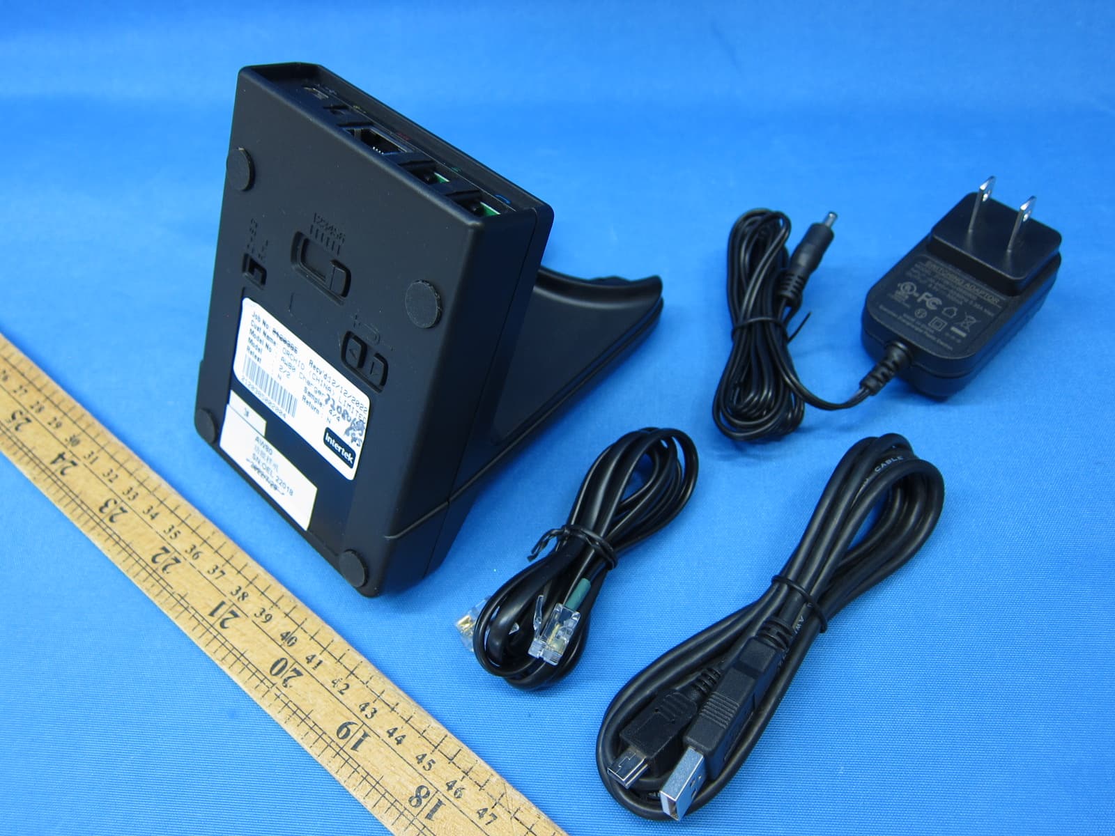
2ALB3AW70
May 30, 2023DECT 6.0 Headsets System - Base(BT) Unit
Equipment Class
DXX - Part 15 Low Power Communication Device Transmitter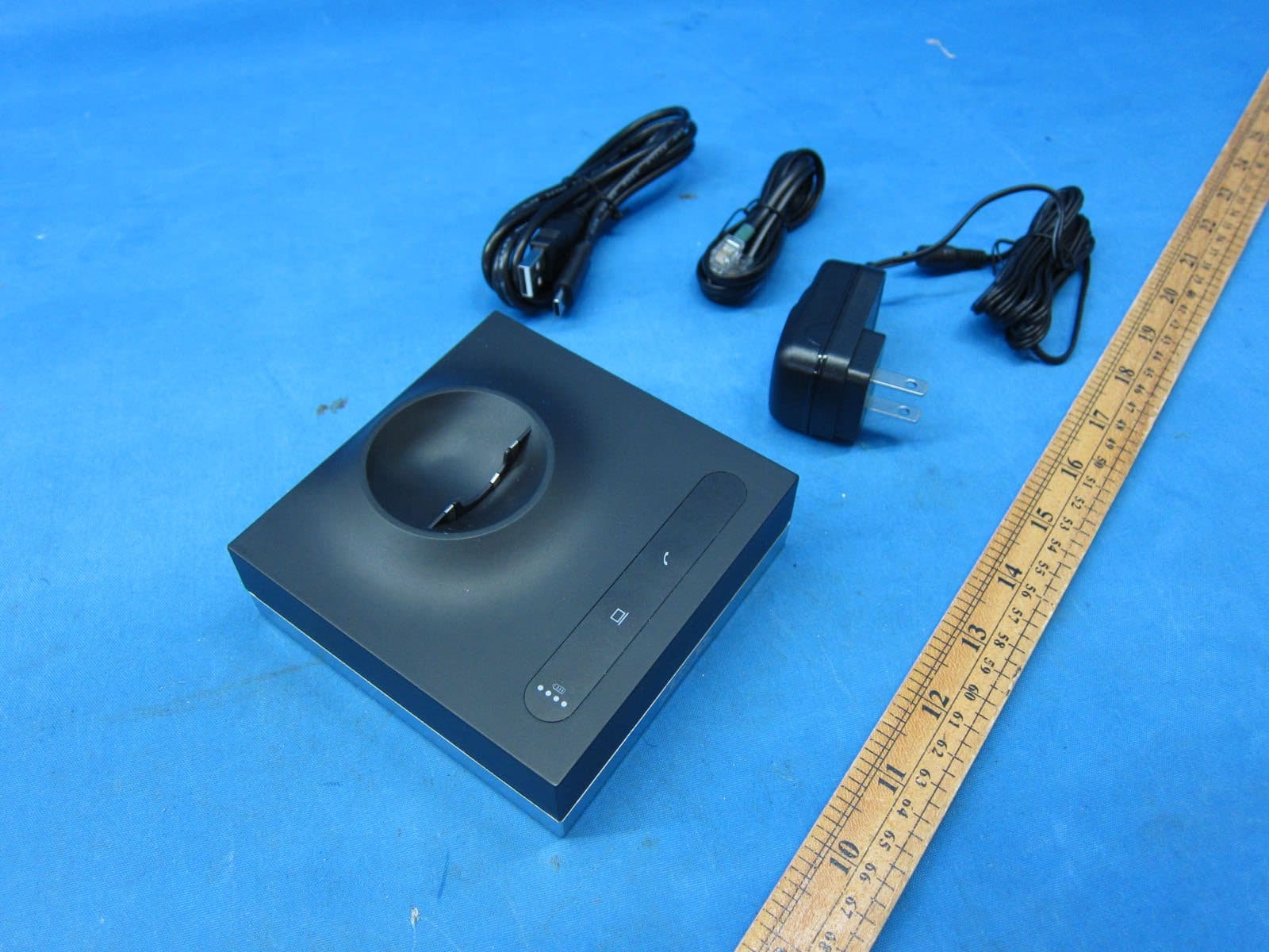
2ALB3LH570BS
Jan 24, 2023DECT 6.0 Cordless telephone - Base Unit
Equipment Class
PUB - Part 15 Unlicensed PCS Base Station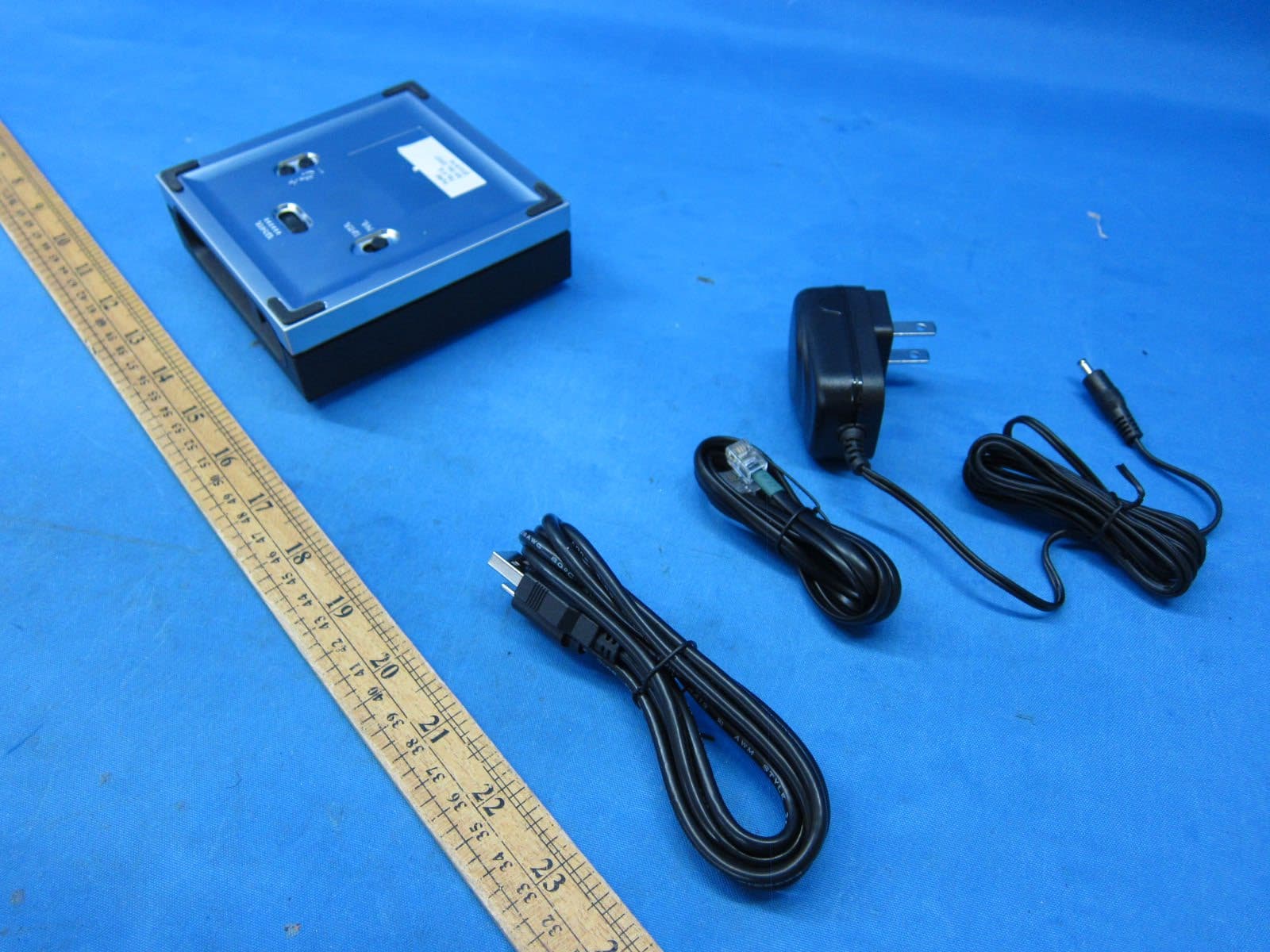
2ALB3LH670BS
Jan 18, 2023DECT 6.0 Headsets System - Base(BT) Unit
Equipment Class
DXX - Part 15 Low Power Communication Device Transmitter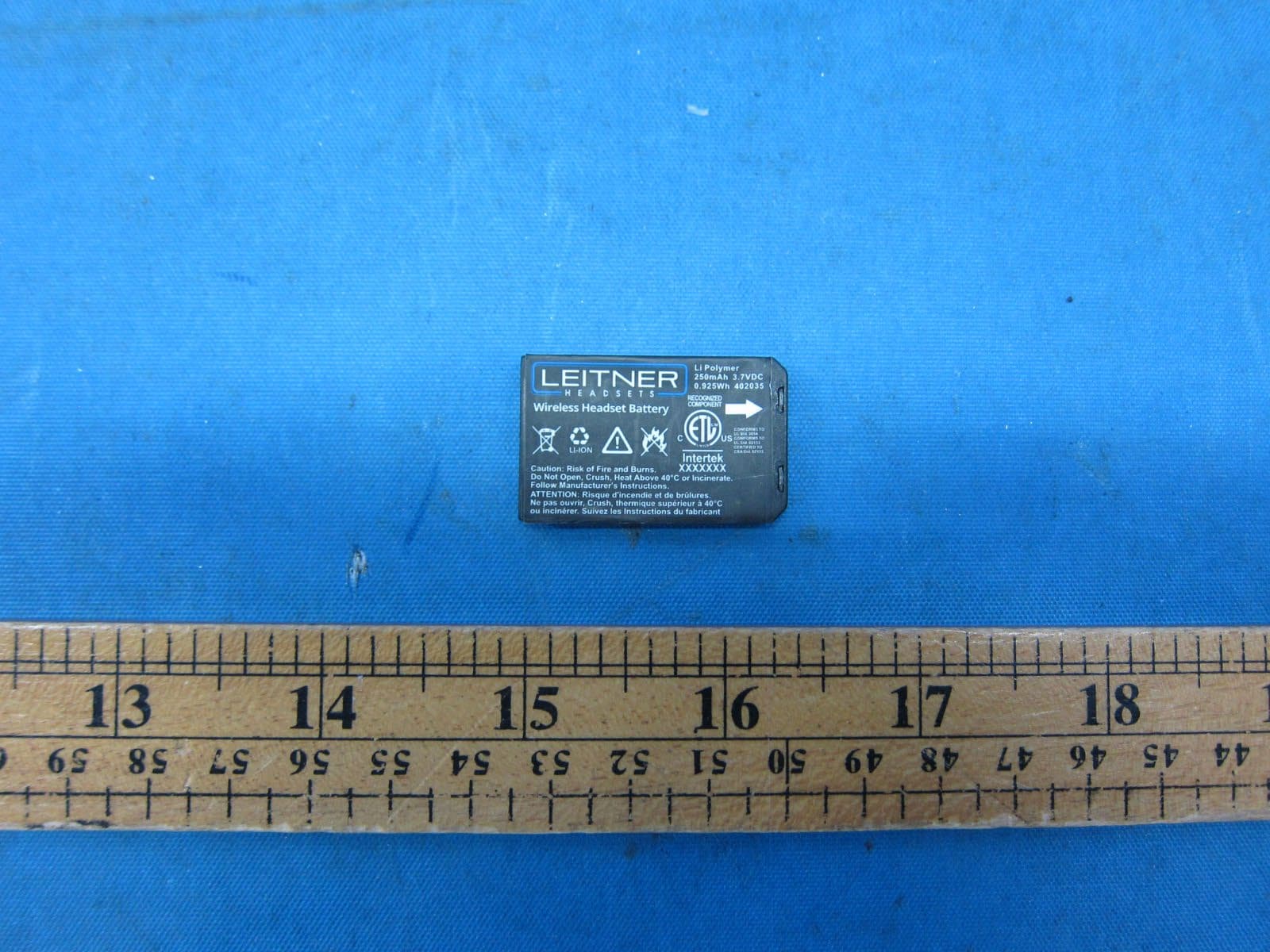
2ALB3LH575HS
Jan 18, 2023DECT 6.0 Wireless Headset
Equipment Class
PUE - Part 15 Unlicensed PCS portable Tx held to ear