2ALJJPL571Smart Phone
PCD, LLC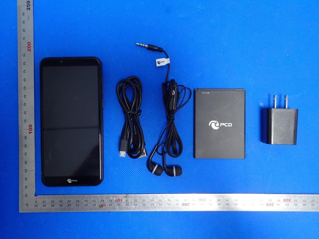
Click to zoom
Application Details
- Equipment Class
- DTS - Digital Transmission System
- Date of Grant
- Apr 14, 2020
- Application Purpose
- Original Equipment
- Date of Application
- Apr 14, 2020
- Equipment Note
- Smart Phone
- Frequency Range
- 2412.00000000 - 2462.00000000
- Company
- PCD, LLC
- Country
- United States
Documents & Files
Document Text
Text extracted from the exhibit documents filed with the FCC. Open a document above to read the original.
Users Manual
Phone Overview Get Started Install the USIM/SIM Install the memory card Remove the back cover Mount/Demount the battery Basic Operations Switch on Touch and hold the Power button until the phone switches on. Note: If you have enabled USIM/SIM locking in the Settings menu, enter the correct PIN number upon power-on before you use the phone. Caution: Three consecutive attempts of entering an incorrect PIN will lock the SIM card. If it is locked, use a PUK provided by the operator to unlock it. Switch off Touch and hold the “Power button” until the Phone Options screen displays. Tap " Power off ” to switch off the phone. Unlock Short press the “Power button” light up the screen, according to the clues of the screen interface can be unlocked. Touchscreen Usage Use your fingers to perform operations directly on icons, buttons, and the on-screen keypad. Tap/Touch/Click Tap the icon of an App to start it. Touch & Hold Touch and hold an item to display a pop-up menu of options. For example, go to Address Book, touch and hold a contact on the Address Book page, and a menu of options pops up. Drag Tap an item on the screen and drag it to another place. Slide/Sweep To sweep vertically or horizontally across the screen, you can view apps, pictures, and webpages in a convenient manner. Scroll Similar to sweeping, but faster. Pinch Put two fingers on the screen to pinch in or out an item, such as a webpage or picture. Home Screen 1. Status bar: allows you to view status icons and notices, such as signal, battery, current time and data service. 2. Notification bar: On the Home screen, tap the status bar and drag it down to display the notification bar. Tap this bar. Then you can view the notices. Touch the return button to switch back to the previous page. 3. App icon: Tap an app to open it. 4. Main menu: Drag it up to enter the app main menu. Phone Settings To display the Settings menu, tap the Settings icon directly. 1.SIM card: In the Settings menu, select WLAN to configure your radio network,choose SIM Card. You can then manage your SIM cards on the pop-up page. 2. Network: In the Settings menu, select WLAN to configure your radio network; or select Traffic usage to View the details of usage; or select Mobile Network configure data services of your phone 3. Sound: In the Settings menu, choose Sound. The allows you to set the volume, enable/disable vibration during ringing, and select ringtones for incoming calls and alarm clock, as well as enable/disable keypad touch sound effect, touch alert tone, and screen lock tone 4. Display: allows you to configure the brightness, wallpaper, automatic device rotation, sleep duration, and font size. 5. Security: In the Settings menu, choose Security. The Security page allows you to set the screen locking mode and USIM/SIM locking mode. 6. Application and notification: In the Settings menu, choose Apps. Then you can view or manage your apps. Note: Disable or unload certain apps if available space is less than 100MB. 7. Message: On the Message page, tap the Menu button and choose Settings, you can open and close message send prompt sound, you can enable/disable Message report obtain,view SMS in SIM. 8. Call: To display the Call Settings page, choose Settings on the Call page. Move/Uninstall apps 1. Access the App main menu from the Home screen. On the ALL App page, tap and hold an app to be put on the Home screen, and drag it left or right to locate it at a proper place. In this way, a desktop app is created. 2. On the All App page, tap and hold an app, and drag it to Uninstall on the desktop. In this way, the app is removed from the phone. Note: You are not allowed to uninstall basic apps of the phone. 3. On the All App page, tap and hold an app, Then select the application information,In this way details about the app is displayed. Call This phone allows you to make or answer a call, initiate an emergency call, and launch a multi-party call. On the bottom left of the Home screen, tap the Dial-up icon. The Dial-up page is displayed. Enter a phone number and choose between card 1 and card 2 to make the call. When you enter the number, the phone will automatically search among all contacts a number that best matches the entered numerals, to facilitate your operation. During a call, tap Add a Call, and this call automatically switches to Silent mode. Enter the number of another contact, tap Dial-up, and the previous call automatically switches to On-hold mode. After the second call is answered, tap Join. In this way, a teleconference is established to achieve a multi-party talk. Note: You need to subscribe to this service from your carrier before you use it. You are also allowed to initiate a call by selecting a phone number from the list of contacts or the Message page. WIFI: WIFI is the wireless local area network, refers to the wireless equipment, for example: the mobile phone with WIFI can be wireless and computer's wireless card, wireless router, etc. Constitute a local area network. Bluetooth: Bluetooth is a radio technology that supports short-range communication (usually within 10m) between devices. Wireless information exchange between mobile phones, pdas, wireless headsets, laptops, peripherals, etc. The use of bluetooth technology can effectively simplify the communication between the mobile communication terminal devices, and also can successfully simplify the communication between the device and the Internet, so that the data transmission becomes more rapid and efficient, for wireless communication to broaden the road. Bluetooth adopts distributed network structure and fast frequency hopping and short packet technology to support point-to-point and point-to-multipoint communication. It works in the universal 2.4GHz ISM (i.e., industrial, scientific and medical) frequency band. Its data rate is 1Mbps.Time division duplex transmission scheme is adopted to realize full duplex transmission. Contacts Tap Contacts to open it. The Contacts page offers manage…
Text truncated - open the document above for the full version.
External Photos
External Photos All VIEW OF EUT TOP VIEW OF EUT BOTTOM VIEW OF EUT FRONT VIEW OF EUT BACK VIEW OF EUT LEFT VIEW OF EUT RIGHT VIEW OF EUT
ID Label/Location Info
FCC ID Label Location
Internal Photos
Internal Photos OPEN VIEW OF EUT(FIGURE 1) GSM/WCDMA /LTE Antenna OPEN VIEW OF EUT(FIGURE 2) OPEN VIEW OF EUT(FIGURE 3) Diversity Antenna BT&WIFI&GPS Antenna GSM&WCDMA<E ANTNENA DIVERSITY ANTENNA BT&WIFI&GPS ANTENNA INTERNAL VIEW OF EUT(FIGURE 1) INTERNAL VIEW OF EUT(FIGURE 2) INTERNAL VIEW OF EUT(FIGURE 3) INTERNAL VIEW OF EUT(FIGURE 4) INTERNAL VIEW OF EUT(FIGURE 5) INTERNAL VIEW OF EUT(FIGURE 6) INTERNAL VIEW OF EUT(FIGURE 7) INTERNAL VIEW OF EUT(FIGURE 8) INTERNAL VIEW OF EUT(FIGURE 9)
Operational Description
Declaration concerning Antenna Specification It is hereby declared that the product Model No.: PL571 FCC ID: 2ALJJPL571 fulfills the requirement in FCC test relating to the antenna type. The device specified above confirms to the FCC recommendations for internal antenna type(s) described below: 1. Type of antenna: PIFA Antenna Gain of the antenna: 0 dBi Frequency range: 2412-2462 MHz & 2402-2480 MHz 2. Type of antenna: PIFA Antenna Gain of the antenna: 2.53 dBi Frequency range: 824.2-848.8 MHz Gain of the antenna: 3.15 dBi Frequency range: 1850.2-1909.8 MHz Gain of the antenna: 3.15dBi Frequency range: 1852.4-1907.6 MHz Gain of the antenna: 2.53 dBi Frequency range: 826.4-846.6 MHz Gain of the antenna: 2.97 dBi Frequency range: 1712.4-1752.6 MHz Gain of the antenna: 3.15 dBi Frequency range: 1850-1909.9 MHz Gain of the antenna: 2.97 dBi Frequency range: 1710-1754.9MHz Gain of the antenna: 2.93 dBi Frequency range: 2500-2569.9MHz 3. Type of antenna: Diversity Antenna Gain of the antenna: 3.01 dBi Frequency range: 1850-1909.9 MHz Gain of the antenna: 2.66 dBi Frequency range: 1710-1754.9MHz Gain of the antenna: 2.87 dBi Frequency range: 2500-2569.9MHz The mounting of the antenna is fixed to the radio module and no other antenna should be used. Company name: PCD, LLC Address: 7651 Southland Blvd. Orlando, FL 32809 USA Place: Orlando Date: 2020-04-14 Signature:
RF Exposure Info
Page 1 of 170 SAR Test Report Report No.: AGC00767200301FH01 FCC ID : 2ALJJPL571 APPLICATION PURPOSE : Original Equipment PRODUCT DESIGNATION : Smart Phone BRAND NAME : PCD MODEL NAME : PL571 APPLICANT : PCD, LLC DATE OF ISSUE : Apr. 08,2020 STANDARD(S) : IEEE Std. 1528:2013 FCC 47 CFR Part 2§2.1093:2013 IEEE C95.1TM:2005 REPORT VERSION : V1.0 Attestation of Global Compliance(Shenzhen) Co., Ltd. CAUTION: This report shall not be reproduced except in full without the written permission of the test laboratory and shall not be quoted out of context. Report No.: AGC00767200301FH01 Page 2 of 170 Report Revise Record Report Version Revise Time Issued Date Valid Version Notes V1.0 / Apr. 08,2020 Valid Initial Release Report No.: AGC00767200301FH01 Page 3 of 170 Test Report Applicant Name PCD, LLC Applicant Address 7651 Southland Blvd. Orlando, FL 32809 Manufacturer Name Shenzhen TENSEN industrial Co.,Ltd. Manufacturer Address 4th Floor,Yufeng Building, Jinhai Road No.6-9,Xixiang street Bao'an District shenzhen Factory Name Shenzhen TENSEN industrial Co.,Ltd. Factory Address 4th Floor,Yufeng Building, Jinhai Road No.6-9,Xixiang street Bao'an District shenzhen Product Designation Smart Phone Brand Name PCD Model Name PL571 EUT Voltage DC3.8V by battery Applicable Standard IEEE Std. 1528:2013 FCC 47 CFR Part 2§2.1093:2013 IEEE C95.1TM:2005 Test Date Mar. 17,2020 to Mar. 25,2020 Report Template AGCRT-US-4G/SAR (2018-01-01) Note: The results of testing in this report apply to the product/system which was tested only. Prepared By Jack Gui (Project Engineer) Mar. 25,2020 Reviewed By Angela Li (Reviewer) Apr. 08,2020 Approved By Forrest Lei (Authorized Officer) Apr. 08,2020 Report No.: AGC00767200301FH01 Page 4 of 170 TABLE OF CONTENTS 1. SUMMARY OF MAXIMUM SAR VALUE ....................................................................................................... 5 2. GENERAL INFORMATION ............................................................................................................................ 6 2.1. EUT DESCRIPTION ...................................................................................................................................... 6 3. SAR MEASUREMENT SYSTEM ..................................................................................................................... 8 3.1. THE SATIMO SYSTEM USED FOR PERFORMING COMPLIANCE TESTS CONSISTS OF FOLLOWING ITEMS .................. 8 3.2. COMOSAR E-FIELD PROBE ....................................................................................................................... 9 3.3. ROBOT ....................................................................................................................................................... 9 3.4. VIDEO POSITIONING SYSTEM ..................................................................................................................... 10 3.5. DEVICE HOLDER ....................................................................................................................................... 10 3.6. SAM TWIN PHANTOM ................................................................................................................................. 11 4. SAR MEASUREMENT PROCEDURE ........................................................................................................... 12 4.1. SPECIFIC ABSORPTION RATE (SAR) ........................................................................................................... 12 4.2. SAR MEASUREMENT PROCEDURE ............................................................................................................. 13 4.3. RF EXPOSURE CONDITIONS ....................................................................................................................... 15 5. TISSUE SIMULATING LIQUID ...................................................................................................................... 17 5.1. THE COMPOSITION OF THE TISSUE SIMULATING LIQUID ................................................................................... 17 5.2. TISSUE DIELECTRIC PARAMETERS FOR HEAD AND BODY PHANTOMS ............................................................. 18 5.3. TISSUE CALIBRATION RESULT ..................................................................................................................... 19 6. SAR SYSTEM CHECK PROCEDURE ......................................................................................................... 21 6.1. SAR SYSTEM CHECK PROCEDURES ........................................................................................................... 21 6.2. SAR SYSTEM CHECK ................................................................................................................................ 22 7. EUT TEST POSITION ................................................................................................................................... 24 7.1. DEFINE TWO IMAGINARY LINES ON THE HANDSET ......................................................................................... 24 7.2. CHEEK POSITION ...................................................................................................................................... 25 7.3. TILT POSITION ........................................................................................................................................... 25 7.4. BODY WORN POSITION .............................................................................................................................. 26 8. SAR EXPOSURE LIMITS ............................................................................................................................ 27 9. TEST FACILITY ........................................................................................................................................... 28 10. TEST EQUIPMENT LIST ..............................................................................…
Text truncated - open the document above for the full version.
RF Exposure Info
Report No.: AGC00767200301FH01 Page 101 of 170 Report No.: AGC00767200301FH01 Page 102 of 170 Z (mm) 0.00 4.00 9.00 14.00 19.00 24.00 29.00 SAR (W/Kg) 0.1337 0.1026 0.0752 0.0565 0.0422 0.0337 0.0245 3D screen shot Hot spot position Report No.: AGC00767200301FH01 Page 103 of 170 Test Laboratory: AGC Lab Date: Mar. 25,2020 GPRS 850 Mid- Body- Back (2up) DUT: Smart Phone; Type: PL571 Communication System: GPRS-2 Slot; Communication System Band: GSM 850; Duty Cycle: 1:4.2; Conv.F=5.19; Frequency: 836.6 MHz; Medium parameters used: f = 835 MHz; σ= 0.89 mho/m; εr = 41.95; ρ= 1000 kg/m³ ; Phantom section: Flat Section Ambient temperature (°C): 21.1, Liquid temperature (°C): 20.8 SATIMO Configuration: • Probe: SSE5; Calibrated: Jun. 04,2019; Serial No.: SN 22/16 EP315 • Sensor-Surface: 4mm (Mechanical Surface Detection) • Phantom: SAM twin phantom • Measurement SW: OpenSAR V4_02_35 Configuration/GPRS 850 Mid-Body-Back/Area Scan: Measurement grid: dx=8mm, dy=8mm Configuration/GPRS 850 Mid-Body-Back/Zoom Scan: Measurement grid: dx=8mm,dy=8mm, dz=5mm; Area Scan surf_sam_plan.txt, h= 5.00 mm Zoom Scan 5x5x7,dx=8mm dy=8mm dz=5mm,Complete Phantom Validation plane Device Position Body Back Band GSM 850 Channels Middle Signal TDMA (Crest factor: 4.0) SURFACE SAR VOLUME SAR Maximum location: X=5.00, Y=31.00 SAR Peak: 0.31 W/kg SAR 10g (W/Kg) 0.121071 SAR 1g (W/Kg) 0.180659 Report No.: AGC00767200301FH01 Page 104 of 170 Report No.: AGC00767200301FH01 Page 105 of 170 Z (mm) 0.00 4.00 9.00 14.00 19.00 24.00 29.00 SAR (W/Kg) 0.2950 0.1735 0.1061 0.0954 0.0819 0.0635 0.0460 3D screen shot Hot spot position Report No.: AGC00767200301FH01 Page 106 of 170 Test Laboratory: AGC Lab Date: Mar. 17,2020 PCS 1900 Mid-Touch- Left <SIM 1> DUT: Smart Phone; Type: PL571 Communication System: Generic GSM; Communication System Band: PCS 1900; Duty Cycle: 1:8.3; Conv.F=4.48; Frequency: 1880 MHz; Medium parameters used: f = 1850 MHz; σ= 1.35 mho/m; εr =40.32; ρ= 1000 kg/m³ ; Phantom section: Left Section Ambient temperature (°C): 20.9, Liquid temperature (°C): 20.6 SATIMO Configuration: • Probe: SSE5; Calibrated: Jun. 04,2019; Serial No.: SN 22/16 EP315 • Sensor-Surface: 4mm (Mechanical Surface Detection) • Phantom: SAM twin phantom • Measurement SW: OpenSAR V4_02_35 Configuration/PCS1900 Mid-Touch-Left/Area Scan: Measurement grid: dx=8mm, dy=8mm Configuration/PCS1900 Mid-Touch-Left/Zoom Scan: Measurement grid: dx=8mm,dy=8mm, dz=5mm; Area Scan dx=8mm dy=8mm, h= 5.00 mm ZoomScan 5x5x7,dx=8mm dy=8mm dz=5mm,Complete Phantom Left head Device Position Cheek Band PCS 1900 Channels Middle Signal TDMA (Crest factor: 8.0) SURFACE SAR VOLUME SAR Maximum location: X=-56.00, Y=-65.00 SAR Peak: 0.16 W/kg SAR 10g (W/Kg) 0.060370 SAR 1g (W/Kg) 0.100936 Report No.: AGC00767200301FH01 Page 107 of 170 Report No.: AGC00767200301FH01 Page 108 of 170 Z (mm) 0.00 4.00 9.00 14.00 19.00 24.00 29.00 SAR (W/Kg) 0.1373 0.1018 0.0688 0.0480 0.0313 0.0220 0.0143 3D screen shot Hot spot position Report No.: AGC00767200301FH01 Page 109 of 170 Test Laboratory: AGC Lab Date: Mar. 17,2020 PCS 1900 Mid-Body-Back (MS)<SIM 1> DUT: Smart Phone; Type: PL571 Communication System: Generic GSM; Communication System Band: PCS 1900; Duty Cycle: 1:8.3; Conv.F=4.60; Frequency: 1880 MHz; Medium parameters used: f = 1850 MHz; σ= 1.35 mho/m; εr =40.32; ρ= 1000 kg/m³ ; Phantom section: Flat Section Ambient temperature (°C): 20.9, Liquid temperature (°C): 20.6 SATIMO Configuration: • Probe: SSE5; Calibrated: Jun. 04,2019; Serial No.: SN 22/16 EP315 • Sensor-Surface: 4mm (Mechanical Surface Detection) • Phantom: SAM twin phantom • Measurement SW: OpenSAR V4_02_35 Configuration/PCS1900 Mid-Body-Back/Area Scan: Measurement grid: dx=8mm, dy=8mm Configuration/PCS1900 Mid-Body-Back/Zoom Scan: Measurement grid: dx=8mm,dy=8mm, dz=5mm; Area Scan surf_sam_plan.txt, h= 5.00 mm ZoomScan 5x5x7,dx=8mm dy=8mm dz=5mm,Complete Phantom Validation plane Device Position Body Back Band PCS 1900 Channels Middle Signal TDMA (Crest factor: 8.0) SURFACE SAR VOLUME SAR Maximum location: X=5.00, Y=-55.00 SAR Peak: 0.60 W/kg SAR 10g (W/Kg) 0.213390 SAR 1g (W/Kg) 0.383537 Report No.: AGC00767200301FH01 Page 110 of 170 Report No.: AGC00767200301FH01 Page 111 of 170 Z (mm) 0.00 4.00 9.00 14.00 19.00 24.00 29.00 SAR (W/Kg) 0.5804 0.4085 0.2559 0.1610 0.0959 0.0607 0.0376 3D screen shot Hot spot position Report No.: AGC00767200301FH01 Page 112 of 170 Test Laboratory: AGC Lab Date: Mar. 17,2020 GPRS 1900 High-Edge 3(3up) DUT: Smart Phone; Type: PL571 Communication System: GPRS-3Slot; Communication System Band: PCS 1900; Duty Cycle: 1:2.7; Conv.F=4.60; Frequency: 1909.8 MHz; Medium parameters used: f = 1850 MHz; σ= 1.39 mho/m; εr =38.92; ρ= 1000 kg/m³ ; Phantom section: Flat Section Ambient temperature (°C): 20.9, Liquid temperature (°C): 20.6 SATIMO Configuration: • Probe: SSE5; Calibrated: Jun. 04,2019; Serial No.: SN 22/16 EP315 • Sensor-Surface: 4mm (Mechanical Surface Detection) • Phantom: SAM twin phantom • Measurement SW: OpenSAR V4_02_35 Configuration/GPRS1900 High-Edge 3/Area Scan: Measurement grid: dx=8mm, dy=8mm Configuration/GPRS1900 High-Edge 3/Zoom Scan: Measurement grid: dx=8mm,dy=8mm, dz=5mm; Area Scan surf_sam_plan.txt, h= 5.00 mm Zoom Scan 5x5x7,dx=8mm dy=8mm dz=5mm,Complete Phantom Validation plane Device Position Edge 3 Band PCS 1900 Channels High Signal TDMA (Crest factor: 2.7) SURFACE SAR VOLUME SAR Maximum location: X=5.00, Y=-15.00 SAR Peak: 1.47 W/kg SAR 10g (W/Kg) 0.528394 SAR 1g (W/Kg) 0.944077 Report No.: AGC00767200301FH01 Page 113 of 170 Report No.: AGC00767200301FH01 Page 114 of 170 Z (mm) 0.00 4.00 9.00 14.00 19.00 24.00 29.00 SAR (W/Kg) 1.4726 1.0255 0.6435 0.3907 0.2532 0.1519 0.0998 3D screen shot Hot spot position Report No.: AGC00767200301FH01 Page 115 of 170 Test Laboratory: AGC Lab Date: Mar. 17,2020 WCDMA Band II Mid-Touch-Right (RMC) DUT: Smart Phone; Type: PL571 Communication System: UMTS; Communication System Band: Band II UTRA/FDD ;Duty Cycle:1:1; Conv.F=4.48; Frequ…
Text truncated - open the document above for the full version.
Test Report
Page 1 of 41 FCC Test Report Report No.: AGC00767200301FE08 FCC ID : 2ALJJPL571 APPLICATION PURPOSE : Original Equipment PRODUCT DESIGNATION : Smart Phone BRAND NAME : PCD MODEL NAME : PL571 APPLICANT : PCD, LLC DATE OF ISSUE : Apr. 07, 2020 STANDARD(S) : FCC Part 15.247 REPORT VERSION : V1.0 Attestation of Global Compliance (Shenzhen) Co., Ltd CAUTION: This report shall not be reproduced except in full without the written permission of the test laboratory and shall not be quoted out of context. Report No.: AGC00767200301FE08 Page 2 of 41 REPORT REVISE RECORD Report Version Revise Time Issued Date Valid Version Notes V1.0 / Apr. 07, 2020 Valid Initial Release Report No.: AGC00767200301FE08 Page 3 of 41 TABLE OF CONTENTS 1. VERIFICATION OF COMPLIANCE ............................................................................................................... 5 2.GENERAL INFORMATION ............................................................................................................................. 6 2.1PRODUCT DESCRIPTION ........................................................................................................................ 6 2.2. TABLE OF CARRIER FREQUENCYS .................................................................................................... 6 2.3 RELATED SUBMITTAL(S)/GRANT(S) ..................................................................................................... 7 2.4TEST METHODOLOGY ............................................................................................................................ 7 2.5 SPECIAL ACCESSORIES ........................................................................................................................ 7 2.6 EQUIPMENT MODIFICATIONS ............................................................................................................... 7 3. MEASUREMENT UNCERTAINTY ................................................................................................................. 8 4. DESCRIPTION OF TEST MODES ................................................................................................................. 9 5. SYSTEM TEST CONFIGURATION ............................................................................................................. 10 5.1 CONFIGURATION OF TESTED SYSTEM ............................................................................................. 10 5.2 EQUIPMENT USED IN TESTED SYSTEM ............................................................................................ 10 5.3. SUMMARY OF TEST RESULTS ........................................................................................................... 10 6. TEST FACILITY ........................................................................................................................................... 11 7. PEAK OUTPUT POWER ............................................................................................................................. 12 7.1. MEASUREMENT PROCEDURE ........................................................................................................... 12 7.2. TEST SET-UP (BLOCK DIAGRAM OF CONFIGURATION) ................................................................. 12 7.3. LIMITS AND MEASUREMENT RESULT ............................................................................................... 13 8. 6 DB BANDWIDTH ...................................................................................................................................... 15 8.1. MEASUREMENT PROCEDURE ........................................................................................................... 15 8.2. TEST SET-UP (BLOCK DIAGRAM OF CONFIGURATION) ................................................................. 15 8.3. LIMITS AND MEASUREMENT RESULTS ............................................................................................ 15 9. CONDUCTED SPURIOUS EMISSION ........................................................................................................ 17 9.1. MEASUREMENT PROCEDURE ........................................................................................................... 17 9.2. TEST SET-UP (BLOCK DIAGRAM OF CONFIGURATION) ................................................................. 17 9.3. MEASUREMENT EQUIPMENT USED .................................................................................................. 17 9.4. LIMITS AND MEASUREMENT RESULT ............................................................................................... 17 10. MAXIMUM CONDUCTED OUTPUT POWER SPECTRAL DENSITY ....................................................... 22 10.1 MEASUREMENT PROCEDURE .......................................................................................................... 22 10.2 TEST SET-UP (BLOCK DIAGRAM OF CONFIGURATION) ................................................................ 22 10.3 MEASUREMENT EQUIPMENT USED ................................................................................................. 22 10.4 LIMITS AND MEASUREMENT RESULT .............................................................................................. 22 11. RADIATED EMISSION ............................................................................................................................... 24 Report No.: AGC00767200301FE08 Page 4 of 41 11.1. MEASUREMENT PROCEDURE ......................................................................................................... 24 11.2. TEST SETUP ....................................................................................................................................... 25 11.3. LIMITS AND MEASUREMENT RESULT ............................................................................................. 26 11.4. TEST RESULT .......................................................................................................…
Text truncated - open the document above for the full version.
Test Report
Page1of 66 Report No.:AGC00767200301FE04 FCC ID : 2ALJJPL571 APPLICATION PURPOSE : Original Equipment PRODUCT DESIGNATION : Smart Phone BRAND NAME : PCD MODEL NAME : PL571 APPLICNAT : PCD, LLC DATE OF ISSUE : Apr. 07, 2020 STANDARD(S) TEST PROCEDURE(S) : FCC Part 15.247 KDB 558074 D01 DTS Meas Guidance v04 REPORT VERSION : V1.0 Attestation of Global Compliance (Shenzhen) Co., Ltd CAUTION: This report shall not be reproduced except in full without the written permission of the test laboratory and shall not be quoted out of context. FCC Test Report Report No.:AGC00767200301FE04 Page 2 of 66 Report Revise Record Report Version Revise Time Issued Date Valid Version Notes V1.0 / Apr. 07, 2020 Valid Initial Release Report No.:AGC00767200301FE04 Page 3 of 66 TABLE OF CONTENTS 1. VERIFICATION OF CONFORMITY ............................................................................................................... 5 2. GENERAL INFORMATION ............................................................................................................................ 6 2.1. PRODUCT DESCRIPTION ..................................................................................................................... 6 2.2. TABLE OF CARRIER FREQUENCYS ..................................................................................................... 6 2.3. IEEE 802.11N MODULATION SCHEME .................................................................................................. 7 2.4. RELATED SUBMITTAL(S) / GRANT (S) .................................................................................................. 7 2.5. TEST METHODOLOGY .......................................................................................................................... 8 2.6. SPECIAL ACCESSORIES ....................................................................................................................... 8 2.7. EQUIPMENT MODIFICATIONS .............................................................................................................. 8 3. MEASUREMENT UNCERTAINTY ................................................................................................................. 9 4. DESCRIPTION OF TEST MODES ............................................................................................................... 10 5 SYSTEM TEST CONFIGURATION .............................................................................................................. 11 5.1. CONFIGURATION OF EUT SYSTEM .................................................................................................... 11 5.2. EQUIPMENT USED IN EUT SYSTEM .................................................................................................... 11 5.3. SUMMARY OF TEST RESULTS ............................................................................................................. 11 6. TEST FACILITY ........................................................................................................................................... 12 6. OUTPUT POWER ........................................................................................................................................ 13 6.1. MEASUREMENT PROCEDURE ........................................................................................................... 13 6.2. TEST SET-UP (BLOCK DIAGRAM OF CONFIGURATION) ................................................................... 13 6.3. LIMITS AND MEASUREMENT RESULT ............................................................................................... 14 7. 6DB BANDWIDTH ....................................................................................................................................... 16 7.1. MEASUREMENT PROCEDURE ........................................................................................................... 16 7.2. TEST SET-UP (BLOCK DIAGRAM OF CONFIGURATION) .…
Text truncated - open the document above for the full version.
Contact Information
Applicant
Mauricio Velasco(Chief Technology Officer)
Test Firm
Attestation of Global Compliance (Shenzhen) Co., LDoris Li
[email protected]+86-755-25234088
Technical Specifications
| # | Rule Parts | Frequency Range | Power Output |
|---|---|---|---|
| 2 | 15C | 2.41 GHz - 2.46 GHz | 55.00 mW |
Other Applications from PCD, LLC
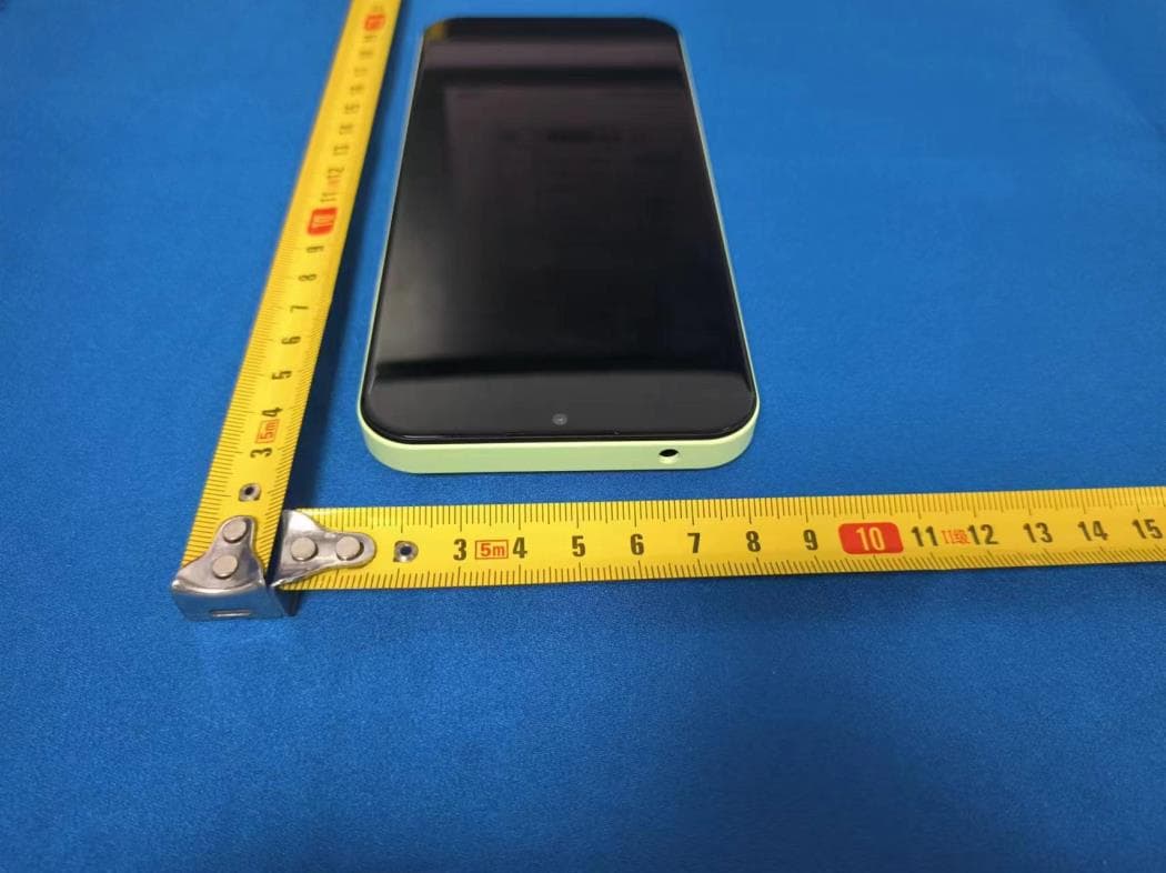
2ALJJP65R
Jul 08, 20244G LTE smart phone
Equipment Class
DTS - Digital Transmission System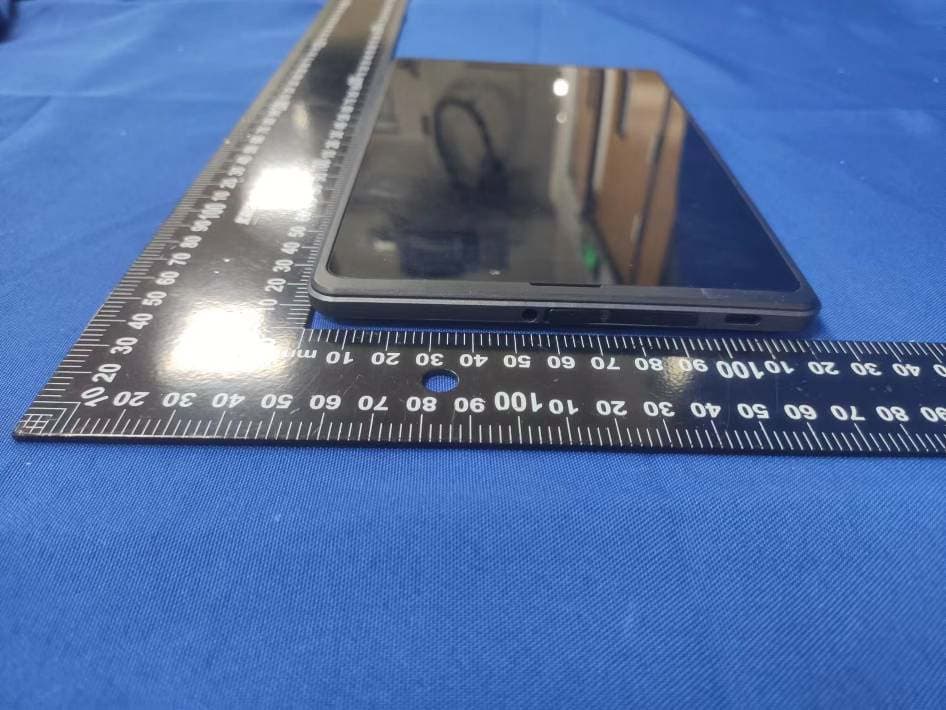
2ALJJT85
Jan 16, 2023TABLET
Equipment Class
DTS - Digital Transmission System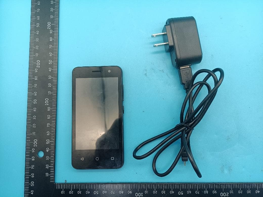
2ALJJP41
Dec 11, 2022Mobile phone
Equipment Class
DTS - Digital Transmission System
2ALJJP40
Aug 01, 2021Mobile phone
Equipment Class
PCE - PCS Licensed Transmitter held to ear
2ALJJU15
Jun 14, 2020mobile phone
Equipment Class
JBP - Part 15 Class B Computing Device Peripheral