2AMFC-AQS1Air Quality Sensor
Dalian Cloud Force Technologies Co., Ltd.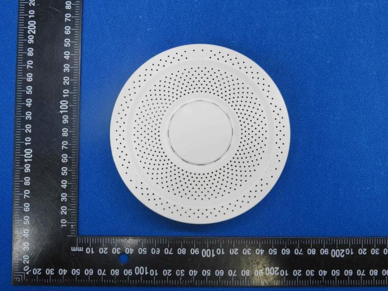
Click to zoom
Application Details
- Equipment Class
- DTS - Digital Transmission System
- Date of Grant
- Sep 18, 2023
- Application Purpose
- Original Equipment
- Date of Application
- Sep 18, 2023
- Equipment Note
- Air Quality Sensor
- Frequency Range
- 2412.00000000 - 2462.00000000
- Country
- China
Documents & Files
Document Text
Text extracted from the exhibit documents filed with the FCC. Open a document above to read the original.
Users Manual
Air Quality Sensor AQS1 User Manuel This user manual serves as a general guidance for all types of UBIBOT® Smart Air Quality Sensor. Some features, which are marked with asterisk, are available only for specific versions. Please refer to related instructions according to the version you purchased. PACKAGE LIST INTRODUCTION Device 1 User Manual User manual 3 External antenna 2 Note: The 4-prong data cable included with the device supports data transfer. Using other kinds of data cables to connect the PC tool may not work. 1. Basic Features Introduction 1 Indicator Light Configuration Button GND Type-C Port Breathing Light Micro SIM card* Slot 5V Output12V InputRS485 A RS485 B DEVICE SETUP OPTIONS 2. Device Operations Option 1: Using Mobile App Press the configuration button for about 3 seconds until the indicator light flashes red and green alternately and then release the button to enter the setup mode. Under the power-on state, press the Configuration button once, the green light starts flashing at this time to connect to the network and send data. If the red light is on, the data sending failure; if the red light is not on, the data sending success. (After power on, the green light will flash continu- ously for 15 minutes) Double-click the Configuration button to turn voice prompts off or on. At the same time, update the data collected by the device. Under the power-on state, press and hold the configuration button for about 15s until the red indicator lights up, then release the button to restore the factory state. Breathing lamp can light up 4 colors: green, yellow, orange and red. Each color indicates a corresponding value range of the data collected by AQS1. The working status of the breathing lamp (always on, off, breathing, blinking) can be set through the platform. Setup Mode Manual Data Synchronization Switch On/Off Voice Guide Reset to Default Settings Download the App from www.ubibot.com/setup, or search for 'Ubibot' on the AppStore or Google Play. Download the tool from www.ubibot.com/setup. This Tool is a desktop app for device setup. It is also helpful in checking setup failure reasons, MAC address, and offline charts. You can also use it to export offline data stored in the device internal memory. We recommend you try to use the PC Tools in case the App setup fails, because the failure may be due to mobile phone incompatibility. The PC Tools is much easier to operate and suitable for both Mac and Windows. 2 Option 2: Using PC Tools Breathing Light SETUP USING THE APP FOR WiFi CONNECTION Launch the App and log in. On the home page, tap "+" to start adding your device. Then please follow the in-app instructions to complete the setup. You can also view the demonstration video at www.ubibot.com/- setup for step by step guidance. 3 Via our app and web console (http://console.ubibot.com), you are able to view the readings as well as config- ure your device, such as create alert rules, set data syncinterval, etc. You can find and watch the demonstration videos at www.ubibot.com/setup. SETUP USING THE APP FOR MOBILE NETWORK * Before you set up the device on mobile data, please check the APN information of the SIM card used for the UbiBot device. An APN (Access Point Name) provides the details your device needs to connect to mobile data through your network operator. APN details differ by network and you will need to get these from your network operator. With the device off, insert the SIM card as indicated in the picture. Launch the app and log in. Tap the "+" to start seng up the device. Please follow the in-app instructions to complete the setup process. Please note, the setup will fail if you don't have data allowance. New Device Micro SIM Micro SIM card* Slot RS485 COMMUNICATION The RS485 communication function can be set through the platform. When it is turned on, the sensor will collect data every will be uploaded via RS485 after each data collection. The default is off. For more details, please contact your local distributor or online document. SETUP USING PC TOOLS STEP 1. Launch the App and log in. With the device switched on, use the Type-C USB cable provided to connect your device to the computer. The PC Tools will automatically scan and recognize the product ID and enter the device page. STEP 2. Click "Network" on the left menu bar. There, you are able to set up the device on WiFi for all the network models. For the SIM or Ethernet cable setup, please click on the corresponding button to continue. 4 5 DEVICE SPECIFICATIONS WiFi 2.4GHz, channel 1-13Flame resistant ABS φ128mm x 40mm Optimal working conditions: -20 to 50°C, 5-95%RH Built-in memory: 300,000 sending data Type-C (5V/2A), DC 12-24V/1A SIM Supports Micro SIM card (15 x 12 x 0.8mm)* Supports RS485 communication TemperatureRange: -20°C ~ 60°C Accuracy: 0.3°C Range: 10% ~ 90% RH Accuracy: 3% RH Range: 26~126 kPa Range: 0~500 μg/m3 Accuracy: 10 μg/m3@0~100 μg/m3, 10%@100~500 μg/m3 Range: 0~65000 ppb Range: 400~65000 ppm Range: 0~10000 ppm (400‒2000 higher-accuracy measurement range) Accuracy: 30 ppm Humidity Atmospheric Pressure PM1.0/2.5/10 TVOC eCO2 CO2 ① After the device is powered on, the TVOC sensor needs 1 hour of self-calibration to measure accurately. ② The PM sensor needs 35-40 seconds for a single data acquisition, and the CO2 sensor needs 15 seconds. FAQ 1. Device network configuration failure reasons ① Please check whether the WiFi account password is correct; ② Please check whether the router is working properly and the network connection is normal; ③ Please make sure the device has entered the WiFi configuration mode; ④ Please check whether the WiFi band is 2.4GHz and the channel is between 1~13; ⑤ Please check the WiFi channel width is set to 20MHz or auto mode; ⑥ WiFi security type: LD1 supports OPEN, WEP and WPA/WPA2-personal; ⑦ Poor signal strength, please check the WiFi or cell phone data traffic signal strength. 2. Reasons for failure to send device data 3. Can the device be used in a network-f…
Text truncated - open the document above for the full version.
Cover Letter(s)
Sincerely, Name/Title: wang mao/Manager Company: Dalian Cloud Force Technologies Co., Ltd. Address: Unit1,Block B,6th Floor, No.23 Honggang Rd. Ganjingzi Distr. Dalian, Liaoning Province China Phone: +86 041186686675 Fax: N/A E-Mail: [email protected]
External Photos
Shenzhen HTT Technology Co., Ltd. Report No.: HTT202309010 Shenzhen HTT Technology Co.,Ltd. Tel: 0755-23595200 Fax: 0755-23595201 1F, Building B, Huafeng International Robotics Industrial Park,Hangcheng Road, Nanchang Community, Xixiang Street, Bao'an District, Guangdong Province, Shenzhen, China Page 1 of 4 Product Name: Air Quality Sensor Model No.: AQS1 EUT Constructional Details External Photo Report No.: HTT202309010 Shenzhen HTT Technology Co.,Ltd. Tel: 0755-23595200 Fax: 0755-23595201 1F, Building B, Huafeng International Robotics Industrial Park,Hangcheng Road, Nanchang Community, Xixiang Street, Bao'an District, Guangdong Province, Shenzhen, China Page 2 of 4 Report No.: HTT202309010 Shenzhen HTT Technology Co.,Ltd. Tel: 0755-23595200 Fax: 0755-23595201 1F, Building B, Huafeng International Robotics Industrial Park,Hangcheng Road, Nanchang Community, Xixiang Street, Bao'an District, Guangdong Province, Shenzhen, China Page 3 of 4 Report No.: HTT202309010 Shenzhen HTT Technology Co.,Ltd. Tel: 0755-23595200 Fax: 0755-23595201 1F, Building B, Huafeng International Robotics Industrial Park,Hangcheng Road, Nanchang Community, Xixiang Street, Bao'an District, Guangdong Province, Shenzhen, China Page 4 of 4 ------End------
ID Label/Location Info
Label and Location Size: L: 4.0cm*W: 3.0cm Label and Location Model No.: AQS1 FCC ID : 2AMFC-AQS1
Internal Photos
Shenzhen HTT Technology Co., Ltd. Report No.: HTT202309010 Shenzhen HTT Technology Co.,Ltd. Tel: 0755-23595200 Fax: 0755-23595201 1F, Building B, Huafeng International Robotics Industrial Park,Hangcheng Road, Nanchang Community, Xixiang Street, Bao'an District, Guangdong Province, Shenzhen, China Page 1 of 3 Product Name: Air Quality Sensor Model No.: AQS1 EUT Constructional Details Internal Photo Report No.: HTT202309010 Shenzhen HTT Technology Co.,Ltd. Tel: 0755-23595200 Fax: 0755-23595201 1F, Building B, Huafeng International Robotics Industrial Park,Hangcheng Road, Nanchang Community, Xixiang Street, Bao'an District, Guangdong Province, Shenzhen, China Page 2 of 3 Report No.: HTT202309010 Shenzhen HTT Technology Co.,Ltd. Tel: 0755-23595200 Fax: 0755-23595201 1F, Building B, Huafeng International Robotics Industrial Park,Hangcheng Road, Nanchang Community, Xixiang Street, Bao'an District, Guangdong Province, Shenzhen, China Page 3 of 3 ------End------
RF Exposure Info
RF Exposure evaluation FCC ID: 2AMFC-AQS1 Exposure category: General population/uncontrolled environment EUT Type: Production Unit Device Type: Mobile Device 1. Reference According to §1.1307(b)(1), systems operating under the provisions of this section shall be operated in a manner that ensures that the public is not exposed to radio frequency energy level in excess of the Commission’s guidelines. According to §1.1310 and §2.1091 RF exposure is calculated. KDB447498 D01: Mobile and Portable Devices RF Exposure Procedures and Equipment Authorization Policies 2. Limit Limits for Maximum Permissible Exposure (MPE)/Controlled Exposure Frequency Range(MHz) Electric Field Strength(V/m) Magnetic Field Strength(A/m) Power Density (mW/cm²) Averaging Time (minute) Limits for Occupational/Controlled Exposure 0.3 – 3.0 3.0 – 30 30 – 300 300 – 1500 1500 – 100,000 614 1842/f 61.4 / / 1.63 4.89/f 0.163 / / (100) * (900/f 2 )* 1.0 f/300 5 6 6 6 6 6 Limits for Maximum Permissible Exposure (MPE)/Uncontrolled Exposure Frequency Range(MHz) Electric Field Strength(V/m) Magnetic Field Strength(A/m) Power Density (mW/cm²) Averaging Time (minute) Limits for Occupational/Controlled Exposure 0.3 – 3.0 3.0 – 30 30 – 300 300 – 1500 1500 – 100,000 614 824/f 27.5 / / 1.63 2.19/f 0.073 / / (100) * (180/f 2 )* 0.2 f/1500 1.0 30 30 30 30 30 F=frequency in MHz *=Plane-wave equivalent power density 3. MPE Calculation Method Predication of MPE limit at a given distance Equation from page 18 of OET Bulletin 65, Edition 97-01 S=PG/4πR² Where: S=power density P=power input to antenna G=power gain of the antenna in the direction of interest relative to an isotropic radiator R=distance to the center of radiation of the antenna 4. Antenna Information AQS1 can only use antennas certificated as follows provided by manufacturer; Antenna No. Model No. of antenna: Type of antenna: Gain of the antenna (Max.) Frequency range: 2.4GWIFI / PCB Antenna 5.30dBi for 2400-2500MHz 5. Manufacturing Tolerance WIFI(Peak) Frequency (MHz) 11b 2412 2437 2462 Target (dBm) 13.0 13.0 13.0 Tolerance ± (dB) 1.0 1.0 1.0 Frequency (MHz) 11g 2412 2437 2462 Target (dBm) 16.0 16.0 16.0 Tolerance ± (dB) 1.0 1.0 1.0 Frequency (MHz) 11n(HT20) 2412 2437 2462 Target (dBm) 17.0 16.0 16.0 Tolerance ± (dB) 1.0 1.0 1.0 Frequency (MHz) 11n(HT40) 2422 2437 2452 Target (dBm) 15.0 15.0 15.0 Tolerance ± (dB) 1.0 1.0 1.0 6. Standalone MPE Result As declared by the Applicant, the EUT is a wireless device used in a fix application, at least 20 cm from any body part of the user or nearby persons; from the maximum EUT RF output power, the minimum separation distance, r =20cm, as well as the gain of the used antenna is 5.3dBi, the RF power density can be obtained. Modulation Type Output power Antenna Gain (dBi) Antenna Gain (linear) MPE (mW/cm 2 ) MPE Limits (mW/cm 2 ) dBm mW 2.4GWIFI 17.0 50.1187 5.3 3.3884 0.0338 1.0000 Remark: 1. Output power (Peak) including turn-up tolerance; 2. MPE evaluate distance is 20cm from user manual provide by manufacturer. 7. Conclusion The measurement results comply with the FCC Limit per 47 CFR 2.1091 for the uncontrolled RF Exposure of mobile device. ----------------THE END OF REPORT---------------
Test Report
Application Note AN043 Small Size 2.4 GHz PCB antenna By Audun Andersen 1 KEYWORDS • CC25xx • CC24xx • CC2480 • PCB antenna • USB dongle • 2.4 GHz • Inverted F Antenna 2 INTRODUCTION The PCB antenna used on the CC2511 USB dongle reference design is described in this application note. Even if the antenna presented is for a USB dongle design it can be used in all 2.4 GHz designs, especially where small space is required for the antenna. This application note describes the antenna dimensions, the RF performance and considerations for complying with regulatory limits when using this design. The suggested antenna design requires no more than 15.2 x 5.7 mm of space and ensures a VSWR ratio of less than 2 across the 2.4 GHz ISM band when connected to a 50 ohm source. Figure 1: CC2511 USB Dongle SWRA117D Page 1 of 21 Application Note AN043 Table of Contents 1 KEYWORDS...................................................................................................................1 2 INTRODUCTION.............................................................................................................1 3 ABBREVIATIONS...........................................................................................................2 4 ANTENNA DESIGN........................................................................................................3 4.1 DESIGN GOALS..........................................................................................................3 4.2 SIMULATION...............................................................................................................3 4.3 LAYOUT AND IMPLEMENTATION...................................................................................4 5 TEST RESULTS.............................................................................................................5 5.1 REFLECTION..............................................................................................................5 5.2 RADIATION PATTERN..................................................................................................7 5.3 OUTPUT POWER......................................................................................................15 5.4 SPURIOUS EMISSION AND HARMONICS......................................................................17 6 CONCLUSION ..............................................................................................................20 7 GENERAL INFORMATION..........................................................................................21 7.1 DOCUMENT HISTORY................................................................................................21 3 ABBREVIATIONS CAD Computer Aided Design CC24xx CC2400, CC2420, CC2430 and CC2431 CC25xx CC2500, CC2510, CC2511, CC2550 and CC2520 CC2480 Z-Accel ZigBee Processor IFA Inverted F Antenna ISM Industrial, Scientific and Medical LOS Line Of Sight PCB Printed Circuit Board PER Packet Error Rate VSWR Voltage Standing Wave Ratio SWRA117D Page 2 of 21 Application Note AN043 4 ANTENNA DESIGN The PCB antenna on the CC2511 USB dongle reference design is a meandered Inverted F Antenna (IFA). The IFA was designed to match an impedance of 50 ohm at 2.45 GHz. Thus no additional matching components are necessary. 4.1 Design Goals The reflection at the feed point of the antenna determines how much of the applied power is delivered to the antenna. A reflection of less than -10 dB across the 2.4 GHz ISM band, when connected to a 50 ohm source, was a design goal. Reflection of less than -10 dB, or VSWR less than 2, ensures that more than 90% of the available power is delivered to the antenna. Bandwidth is in this document defined as the frequency band where more than 90% of the available power is delivered to the antenna. Another design goal was to fit the size of the PCB antenna on a USB dongle and to obtain good performance also when the dongle is connected to a computer. 4.2 Simulation IE3D from Zeland, which is an electromagnetic simulation tool, was used to design the antenna. The accuracy of the simulation is controlled by the mesh. An increase of the mesh increases the simulation time. Thus, for initial simulations mesh = 1 should be used. When a fairly good result is achieved a higher mesh should be used to obtain more accurate results. Comparison of simulation and measurement results shows that the measured reflection is between the result obtained with mesh = 5 and mesh = 1; see Figure 2 for details. Figure 2: Comparison of Simulation and Measurements Results SWRA117D Page 3 of 21 Application Note AN043 4.3 Layout and Implementation Small changes of the antenna dimensions may have large impact on the performance. Therefore it is strongly recommended to make an exact copy of the reference design to achieve optimum performance. The easiest way to implement the antenna is to import the gerber or DXF file showing the antenna layout. These files are named IFA_USB.spl and IFA_USB.dxf respectively and are included in the CC2511 USB dongle reference design available from http://www.ti.com\lpw. The imported file can be used as a template when drawing the antenna. By using this procedure it should be possible to make an exact copy. If the PCB CAD tool being used does not support import of DXF or gerber files, Figure 3 and Table 1 should be used to ensure correct implementation. It is recommended to generate a gerber file for comparison with IFA_USB.spl when making a manual implementation. Most gerber viewers have the possibility to import several gerber files at the same time. Thus by placing the gerber file, showing the manually implemented antenna, on top of IFA_USB.spl it is easy to verify that the antenna is correctly implemented. It is also recommended to use the same thickness and type of PCB material as used in the reference design. Information about the PCB can be found in a separate readme file included in the reference design. To compensate for a thicker/thinner P…
Text truncated - open the document above for the full version.
Test Report
Shenzhen HTT Technology Co., Ltd. Report No.: HTT202309010F01 This results shown in this test report refer only to the sample(s) tested, this test report cannot be reproduced, except in full, without prior written permission of the company. The report would be invalid without specific stamp of test institute and the signatures of compiler and approver. Page 1 of 37 TEST Report Applicant: Dalian Cloud Force Technologies Co., Ltd. Address of Applicant: Unit1,Block B,6th Floor, No.23 Honggang Rd. Ganjingzi Distr. Dalian, Liaoning Province, China Manufacturer : Dalian Cloud Force Technologies Co., Ltd. Address of Manufacturer : Unit1,Block B,6th Floor, No.23 Honggang Rd. Ganjingzi Distr. Dalian, Liaoning Province, China Equipment Under Test (EUT) Product Name: Air Quality Sensor Model No.: AQS1 Series model: AQS1-A, AQS1-S Trade Mark: Ubibot FCC ID: 2AMFC-AQS1 Applicable standards: FCC CFR Title 47 Part 15 Subpart C Section 15.247 Date of sample receipt: Aug.31,2023 Date of Test: Aug.31,2023~Sep.06,2023 Date of report issued: Sep.06,2023 Test Result : PASS * * In the configuration tested, the EUT complied with the standards specified above. Report No.: HTT202309010F01 Shenzhen HTT Technology Co.,Ltd. Tel: 0755-23595200 Fax: 0755-23595201 1F, Building B, Huafeng International Robotics Industrial Park, Hangcheng Road,Nanchang Community, Xixiang Street, Bao'an District, Shenzhen, Guangdong, China Page 2 of 37 1. Version Version No. Date Description 00 Sep.06,2023 Original Tested/ Prepared By Date: Sep.06,2023 Project Engineer Check By: Date: Sep.06,2023 Reviewer Approved By : Date: Sep.06,2023 Authorized Signature Report No.: HTT202309010F01 Shenzhen HTT Technology Co.,Ltd. Tel: 0755-23595200 Fax: 0755-23595201 1F, Building B, Huafeng International Robotics Industrial Park, Hangcheng Road,Nanchang Community, Xixiang Street, Bao'an District, Shenzhen, Guangdong, China Page 3 of 37 2. Contents Page 1. VERSION ........................................................................................................................................................ 2 2. CONTENTS .................................................................................................................................................... 3 3. TEST SUMMARY ........................................................................................................................................... 4 4. GENERAL INFORMATION ............................................................................................................................ 5 4.1. GENERAL DESCRIPTION OF EUT ................................................................................................................ 5 4.2. TEST MODE ............................................................................................................................................... 7 4.3. DESCRIPTION OF SUPPORT UNITS .............................................................................................................. 7 4.4. DEVIATION FROM STANDARDS .................................................................................................................... 7 4.5. ABNORMALITIES FROM STANDARD CONDITIONS ........................................................................................... 7 4.6. TEST FACILITY ........................................................................................................................................... 7 4.7. TEST LOCATION ......................................................................................................................................... 7 4.8. ADDITIONAL INSTRUCTIONS ........................................................................................................................ 7 5. TEST INSTRUMENTS LIST ........................................................................................................................... 7 6. TEST RESULTS AND MEASUREMENT DATA ........................................................................................... 9 6.1. CONDUCTED EMISSIONS ............................................................................................................................ 9 6.2. CONDUCTED PEAK OUTPUT POWER ......................................................................................................... 12 6.3. CHANNEL BANDWIDTH .............................................................................................................................. 13 6.4. POWER SPECTRAL DENSITY ..................................................................................................................... 16 6.5. BAND EDGE ............................................................................................................................................. 19 6.5.1. Conducted Emission Method ......................................................................................................... 19 6.5.2. Radiated Emission Method ............................................................................................................ 22 6.6. SPURIOUS EMISSION ................................................................................................................................ 24 6.6.1. Conducted Emission Method ......................................................................................................... 24 6.6.2. Radiated Emission Method ............................................................................................................ 29 6.7. ANTENNA REQUIREMENT .......................................................................................................................... 36 7. TEST SETUP PHOTO .................................................................................................................................. 37 8. EUT CONSTRUCTIONAL DETAILS ........................................................................................................... 37 Report No.: HTT…
Text truncated - open the document above for the full version.
Test Setup Photos
Shenzhen HTT Technology Co., Ltd. Report No.: HTT202309010 Shenzhen HTT Technology Co.,Ltd. Tel: 0755-23595200 Fax: 0755-23595201 1F, Building B, Huafeng International Robotics Industrial Park,Hangcheng Road, Nanchang Community, Xixiang Street, Bao'an District, Guangdong Province, Shenzhen, China Page 1 of 2 Product Name: Air Quality Sensor Model No.: AQS1 Test Setup Photo Radiated Emission Report No.: HTT202309010 Shenzhen HTT Technology Co.,Ltd. Tel: 0755-23595200 Fax: 0755-23595201 1F, Building B, Huafeng International Robotics Industrial Park,Hangcheng Road, Nanchang Community, Xixiang Street, Bao'an District, Guangdong Province, Shenzhen, China Page 2 of 2 Conducted Emission ------End------
Contact Information
Applicant
wang mao
Test Firm
Shenzhen HTT Technology Co.,Ltd.Kevin Yang
[email protected]86-755-23595200
Technical Specifications
| # | Rule Parts | Frequency Range | Power Output |
|---|---|---|---|
| 1 | 15C | 2.41 GHz - 2.46 GHz | 50.80 mW |
Other Applications from Dalian Cloud Force Technologies Co., Ltd.
2AMFC-NR1
Aug 07, 2024Smart Network Relay
Equipment Class
DTS - Digital Transmission System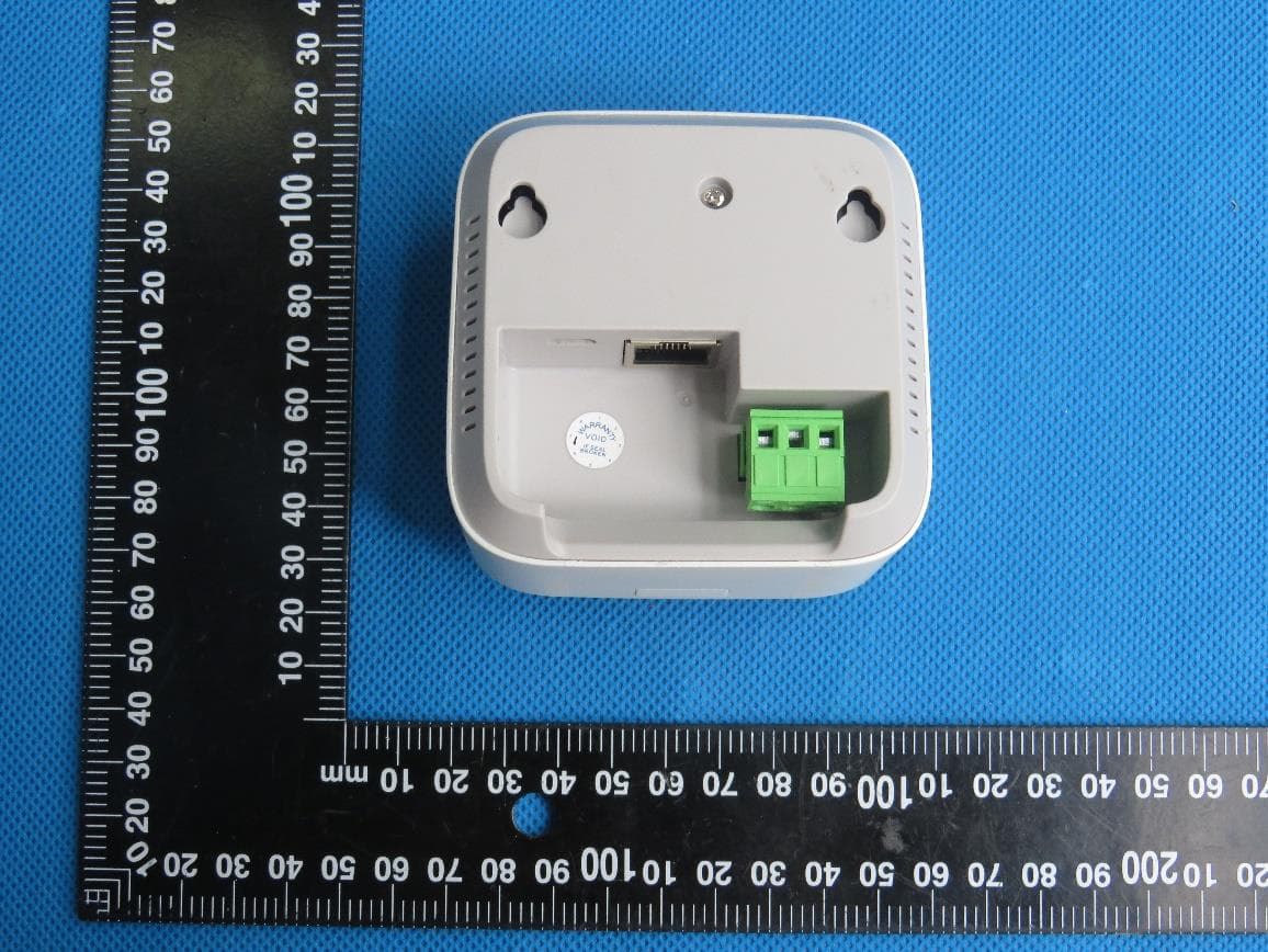
2AMFC-MS1P
May 22, 2021Wireless Motion Sensor
Equipment Class
DSS - Part 15 Spread Spectrum Transmitter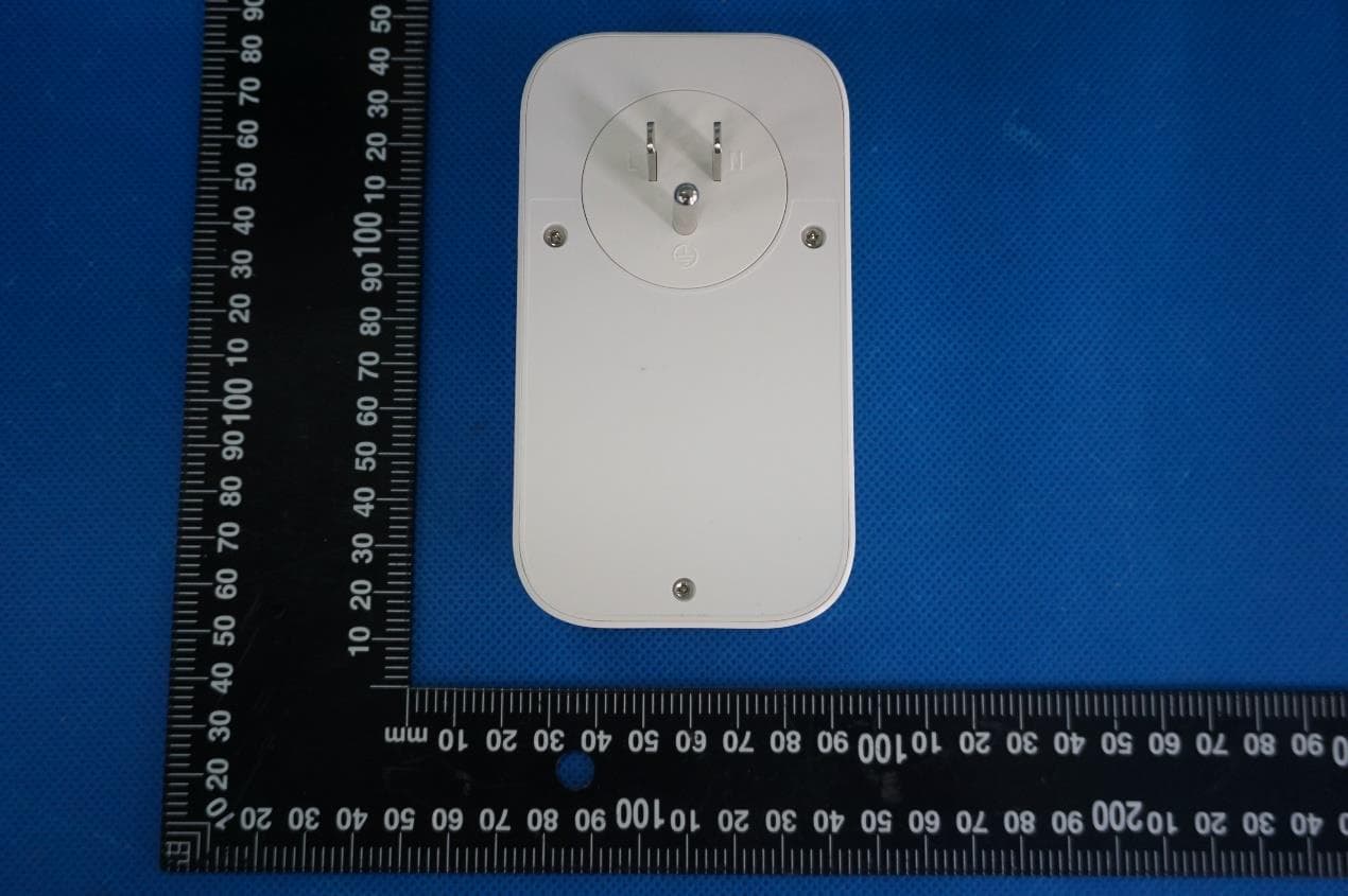
2AMFC-SP1
Dec 28, 2020Ubibot Smart Plug
Equipment Class
DTS - Digital Transmission System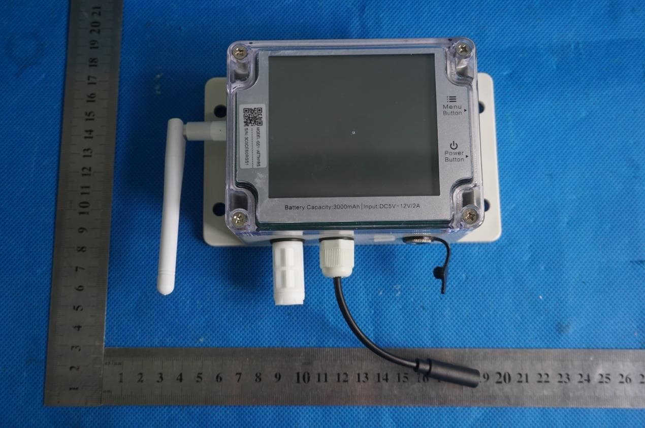
2AMFC-GS1-AETH1RS
Mar 05, 2020Industrial-grade Wireless Smart Multi-Sensor Device GS1
Equipment Class
DTS - Digital Transmission System