2AMFC-NR1Smart Network Relay
Dalian Cloud Force Technologies Co., Ltd.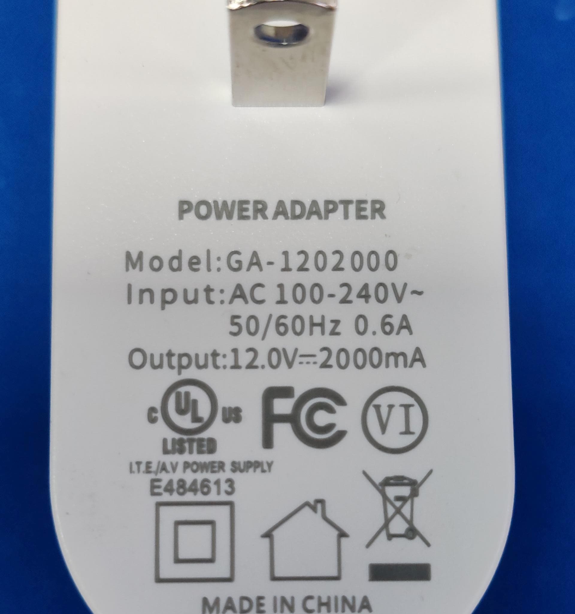
Click to zoom
Application Details
- Equipment Class
- DTS - Digital Transmission System
- Date of Grant
- Aug 07, 2024
- Application Purpose
- Original Equipment
- Date of Application
- Aug 07, 2024
- Equipment Note
- Smart Network Relay
- Frequency Range
- 2412.00000000 - 2462.00000000
- Country
- China
Documents & Files
Document Text
Text extracted from the exhibit documents filed with the FCC. Open a document above to read the original.
Users Manual
Smart Network Relay NR1 User Manual Ethernet cable port* This user manual serves as a general guidance for all types of UBIBOT® Smart Network Relay. Some features, which are marked with asterisk, are available only for specific versions. Please refer to related instructions according to the version you purchased. PACKAGE LIST INTRODUCTION Device 1 User Manual Adapter 3 User manual 4 External antenna 2 Note: Please tighten the antenna before use. WiFi antenna RS485 interface (5V) Wiring terminal RS485 interface (12V) Function button TYPE-CDC12V Device status indicator Relay status indicator Relay output 1. Basic Features Introduction 1 Electrical Wiring 2. Device Operations 1.Interface Switch On/Off After the power is plugged in/unplugged, the device will Switch On/Off automatically. With the device switched on, press and hold the function button for about 5 seconds until the device status indicator flashes red and green alternately. Release at this time to enter the setup mode. Under power-on state, press the function button once, the green device status indicator will flash, then connect to the network and send data. Under power-on state, press and hold the function button for about 15 seconds until the red device status indicator blinks, then release the button to restore factory settings. Setup Mode Send data Reset to Default Settings 2 111213 1234567 8910 14 1516171819 Digital Input 1 Digital Input 2 Digital Input 3 Digital Input 4 Output of DC 12V NO node of Relay 1 COM node of Relay 1 NC node of Relay 1 COM- COM+ 1 2 3 4 5 6 7 8 9 10 NO node of Relay 2 COM node of Relay 2 NC node of Relay 2 NO node of Relay 3 COM node of Relay 3 NC node of Relay3 NO node of Relay 4 COM node of Relay 4 NC node of Relay 4 11 12 13 14 15 16 17 18 19 DEVICE SETUP OPTIONS Option 1: Using Mobile App SETUP USING THE APP FOR WiFi CONNECTION Download the App from www.ubibot.com/setup, or search for 'Ubibot' on the AppStore or Google Play. Download the tool from www.ubibot.com/setup. This tool is a desktop app for device setup. It is also helpful in checking setup failure reasons, MAC address, and offline charts. You can also use it to export offline data stored in the device internal memory. Launch the App and log in. On the home page, tap "+" to start adding your device. Then please follow the in-app instructions to complete the setup. You can also view the demonstration video at www.ubibot.com/- setup for step by step guidance. We recommend you try to use the PC Tools in case the App setup fails, because the failure may be due to mobile phone incompatibility. The PC Tools is much easier to operate and suitable for both Mac and Windows. 5 Option 2: Using PC Tools Via our app and web console (http://console.ubibot.com), you are able to view the readings as well as config- ure your device, such as create alert rules, set data syncinterval, etc. You can find and watch the demonstration videos at www.ubibot.com/setup. NR SETUP USING THE APP FOR ETHERNET CABLE CONNECTION* SETUP USING PC TOOLS STEP 1. Connect the device with power supply and plug the Ethernet cable. STEP 1. Launch the App and log in. With the device switched on, use the Type-C USB cable provided to connect your device to the computer. The PC Tools will automatically scan and recognize the product ID and enter the device page. STEP 2. Click "Network" on the left menu bar. There, you are able to set up the device on WiFi for all the models. For the SIM or Ethernet cable setup, please click on the corresponding button to continue. STEP 2. Launch the app and log in. On the home page, tap "+" to start adding your device. Then please follow the in-app instructions to complete the setup. You can also view the demonstration video at www.ubibot.com/setup for step by step guidance. 6 RS485 COMMUNICATION The default mode is the RS485 communication slave mode. If the external sensor collection time is set in the platform, the master mode for data collection will be activated and the slave mode will be turned off automati- cally. If the device has been networked, the setting parameters are set by the platform. For more details, please contact your local distributor or refer to the online documentation. 7 DEVICE USE 1.Working Mode ① Online control mode: you can remotely control relay operations through the UbiBot cloud platform, including opening/closing the relay, the overall synchronization or independent single-point control, timing and cycle setup, delaying tasks or defining trigger conditions through early warning rules and automation control. ② Pules on/off mode: Pulse ON, i.e., when the relay is in closed state, the relay can be set to disconnect for a period of time (set parameter*0.1s) and then close automatically. Pulse OFF, i.e., when the relay is in discon- nected state, the relay can be set to close for a period of time (set parameter*0.1s) and then disconnect automatically. ③ Local linkage mode: The device has 4 optocoupler inputs, which can be directly linked with the relay. It means that when the optocoupler input signal is effective, the corresponding relay will absorb/disconnect/no action; when the optocoupler input signal is canceled, the corresponding relay will disconnect/absorb/no action. The corresponding relationship between the optocoupler input and the relay's absorption/disconnec- tion/non-activation can be set through the PC tools or the UbiBot platform. ④ Offline control mode: The NR1 device supports the Modbus RTU protocol, allowing for offline control of 4-channel relays through an RS485 connection to a computer. ⑤ Safety interlock mode: The device supports safety interlock setting. if any of the relays set for safety interlocking is turned on, the other relays will be turned off. FAQ DEVICE SPECIFICATION 1. Device network configuration failure reasons ① Please check if the WiFi account password is correct; ② Please check whether the router is working properly and the network connection is normal; ③ Please make sure the device h…
Text truncated - open the document above for the full version.
External Photos
Appendix- NR1-Photos Page 3 of 9 2. Photographs –Constructional Details 2.1. EUT – External View Model MF8410 FCC ID: 2AMFC-NR1 Appendix- NR1-Photos Page 4 of 9 Appendix- NR1-Photos Page 5 of 9 Appendix- NR1-Photos Page 6 of 9 Appendix- NR1-Photos Page 7 of 9
Internal Photos
Appendix- NR1-Photos Page 8 of 9 2.2. EUT – Internal View Model MF8410 FCC ID: 2AMFC-NR1 Appendix- NR1-Photos Page 9 of 9
RF Exposure Info
Waltek Testing Group Co., Ltd. http://www.waltek.com.cn Page 1 of 8 TEST REPORT Referen ce No. .................... : WTD24D06139946W002 FCC ID ................................ : 2AMFC-NR1 Applicant ............................ : Dalian Cloud Force Technologies Co., Ltd. Address .............................. : Unit1,Block B,6th Floor, No.23 Honggang Rd. Ganjingzi Distr. Dalian, Liaoning Province, China Manufacturer .................... : Dalian Cloud Force Technologies Co., Ltd. Address .............................. : Unit1,Block B,6th Floor, No.23 Honggang Rd. Ganjingzi Distr. Dalian, Liaoning Province, China Product ............................... : Smart Network Relay Model(s). ............................ : NR1 Standards........................... : FCC 47CFR Part 2 Subpart J Section 2.1091 Date of Receipt sample .... : 2024-06-20 Date of Test ....................... : 2024-06-20 to 2024-07-19 Date of Issue ...................... : 2024-08-02 Test Result ......................... : Pass Remarks: The re sults shown in this test report refer only to the sample(s) tested, this test report cannot be reproduced, except in full, without prior written permission of the company. The report would be invalid without specific stamp of test institute and the signatures of compiler and approver. Prepared By: Waltek Testing Group Co., Ltd. Address: No. 77, Houjie Section, Guantai Road, Houjie Town, Dongguan City, Guangdong, China Tel: +86-769-2267 6998 Fax: +86-769-2267 6828 Compiled by: Approved by: James Cheng / Project Engineer Deval Qin / Designated Reviewer Reference No.: WTD24D06139946W002 Page 2 of 8 Waltek Testing Group Co., Ltd. http://www.waltek.com.cn 2. Contents Page 1 COVER PAGE ........................................................................................................................................... 1 2. CONTENTS ............................................................................................................................................................ 2 3. REVISION HISTORY ............................................................................................................................................ 3 4. GENERAL INFORMATION .................................................................................................................................. 4 4.1. GENERAL DESCRIPTION OF E.U.T. ............................................................................................................ 4 4.2. DETAILS OF E.U.T. ..................................................................................................................................... 4 4.3. TEST FACILITY ............................................................................................................................................ 5 4.4. SUBCONTRACTED ....................................................................................................................................... 5 4.5. ABNORMALITIES FROM STANDARD CONDITIONS ....................................................................................... 5 5. TEST SUMMARY .................................................................................................................................................. 6 6. RF EXPOSURE ...................................................................................................................................................... 7 6.1. REQUIREMENTS .......................................................................................................................................... 7 6.2. THE PROCEDURES / LIMIT ........................................................................................................................... 7 6.3. MPE CALCULATION METHOD .................................................................................................................... 8 6.4. RADIO FREQUENCY RADIATION EXPOSURE EVALUATION ......................................................................... 8 Reference No.: WTD24D06139946W002 Page 3 of 8 Waltek Testing Group Co., Ltd. http://www.waltek.com.cn 3. Revision History Test Report No. Date of Receipt Sample Date of Test Date of Issue Purpose Comment Approved WTD24D06139946W002 2024-06-20 2024-06-20 to 2024-07-19 2024-08-02Original - Valid Reference No.: WTD24D06139946W002 Page 4 of 8 Waltek Testing Group Co., Ltd. http://www.waltek.com.cn 4. General Information 4.1. General Description of E.U.T. Product: Smart Network Relay Model(s): NR1 Model Description: N/A Test Sample No.: 1-1/1 Wi-Fi Specification: 2.4G-802.11b/g/n HT20/n HT40 Hardware Version: V1.1.0 Software Version: V1.1.4 4.2. Details of E.U.T. Operation Frequency: 802.11b/g/n HT20: 2412~2462MHz 802.11n HT40: 2422~2452MHz Max. RF output power: 17.16dBm Modulation Technology: DSSS, OFDM Antenna installation: Sucker antenna Antenna Gain: -2.19dBi Note: #: The antenna gain is provided by the applicant, and the applicant should be responsible for its authenticity, WALTEK lab has not verified the authenticity of its information. Ratings: DC 12V for Adapter Adapter: Input: AC100-240V~ 50/60Hz 0.6A Output: 12.0V 2000mA Model: GA-1202000 Reference No.: WTD24D06139946W002 Page 5 of 8 Waltek Testing Group Co., Ltd. http://www.waltek.com.cn 4.3. Test Facility The test facility has a test site registered with the following organizations: ISED CAB identifier: CN0013. Test Firm Registration No.: 7760A. Waltek Testing Group Co., Ltd. Has been registered and fully described in a report filed with the Industry Canada. The acceptance letter from the Industry Canada is maintained in our files. Registration number 7760A, October 15, 2016. FCC Designation No.: CN1201. Test Firm Registration No.: 523476. Waltek Testing Group Co., Ltd. EMC Laboratory has been registered and fully described in a report filed with the (FCC) Federal Communications Commission. The acceptance letter from the FCC is maintained in our files. Registration number 523476, Septem…
Text truncated - open the document above for the full version.
Test Report
地址:深圳市龙岗区宝龙街道沙背坜鸿永利工业区 H 栋 TEL:0755-28700870FAX:0755-28483275 Website:www.kxwxjs.com 1 / 14 antenna name: 3 m 5G small sucker /15.5CM high Shenzhen Kexin WIRELESS Technology Co. LTD Antenna specification 地址:深圳市龙岗区宝龙街道沙背坜鸿永利工业区H 栋 TEL:0755-28700870FAX :0755-28483275 Website:www.kxwxjs.com 4 / 14 4、Product performance parameter 电性能指标ElectricalSpecifications 频率范围FrequencyRange (MHz) 700-5900MHz 输入阻抗Input Impendence(Ω) 50 电压驻波比V.S.W.R ≤2.0(未匹配设备/仅供参考) 参考 增益Gain (db i)3DBI( 未匹配设备/仅供参考) 极化形式PolarizationType垂直 Vertical 辐射方向RadiationDirection全向 Omni-Directional 通断测试ContinuityTest通路 最大功率容量Max Power(W) 10W 机械指标MechanicalSpecifications 天线长度AntennaLength(MM) 3000mm 连接器型号ConnectType SMA-J 外壳材质RadomeMaterial ABS 外壳颜色RadomeColor 黑色 工作温度OperatingTemp-25 ~ +75 ̊C 储存温度StorageTemp-25 ~ +75 ̊C 地址:深圳市龙岗区宝龙街道沙背坜鸿永利工业区 H 栋 TEL:0755-28700870FAX:0755-28483275 Website:www.kxwxjs.com 5 / 14 5、product photo 地址:深圳市龙岗区宝龙街道沙背坜鸿永利工业区H 栋 TEL:0755-28700870FAX :0755-28483275 Website:www.kxwxjs.com 6 / 14 6、 VSWR: 地址:深圳市龙岗区宝龙街道沙背坜鸿永利工业区H 栋 TEL:0755-28700870FAX :0755-28483275 Website:www.kxwxjs.com 7 / 14 efficiency gain Frequency(MHz) (工作频段) Efficiency(%) (效率) Peak GAIN (dBi) (增益) 820 28.21-2.49 960 16.04-4.88 1720 11.68-4.97 2180 12.78-5.83 2400 14.93-2.19 2700 6.91-5.83 3300 5.79-6.25 4200 5.42-7.14 5000 1.41-11.62 5900 0.7-14.49 地址:深圳市龙岗区宝龙街道沙背坜鸿永利工业区H 栋 TEL:0755-28700870FAX :0755-28483275 Website:www.kxwxjs.com 8 / 14 2D&3D 地址:深圳市龙岗区宝龙街道沙背坜鸿永利工业区H 栋 TEL:0755-28700870FAX :0755-28483275 Website:www.kxwxjs.com 9 / 14
Test Report
Waltek Testing Group Co., Ltd. http://www.waltek.com.cn Page 1 of 55 TEST REPORT Referen ce No. .................... : WTD24D06139946W001 FCC ID ................................ : 2AMFC-NR1 Applicant ............................ : Dalian Cloud Force Technologies Co., Ltd. Address .............................. : Unit1,Block B,6th Floor, No.23 Honggang Rd. Ganjingzi Distr. Dalian, Liaoning Province, China Manufacturer .................... : Dalian Cloud Force Technologies Co., Ltd. Address .............................. : Unit1,Block B,6th Floor, No.23 Honggang Rd. Ganjingzi Distr. Dalian, Liaoning Province, China Product ............................... : Smart Network Relay Model(s). ............................ : NR1 Standards........................... : FCC 47CFR Part 15.247 Date of Receipt sample .... : 2024-06-20 Date of Test ....................... : 2024-06-20 to 2024-07-19 Date of Issue ...................... : 2024-08-02 Test Result ......................... : Pass Remarks: The re sults shown in this test report refer only to the sample(s) tested, this test report cannot be reproduced, except in full, without prior written permission of the company. The report would be invalid without specific stamp of test institute and the signatures of compiler and approver. Prepared By: Waltek Testing Group Co., Ltd. Address: No. 77, Houjie Section, Guantai Road, Houjie Town, Dongguan City, Guangdong, China Tel: +86-769-2267 6998 Fax: +86-769-2267 6828 Compiled by: Approved by: James Cheng / Project Engineer Deval Qin / Designated Reviewer Reference No.: WTD24D06139946W001 Page 2 of 55 Waltek Testing Group Co., Ltd. http://www.waltek.com.cn 2 Contents Page 1 COVER PAGE ........................................................................................................................................... 1 2 CONTENTS ............................................................................................................................................... 2 3 REVISION HISTORY ................................................................................................................................. 4 4 GENERAL INFORMATION ....................................................................................................................... 5 4.1 GENERAL DESCRIPTION OF E.U.T. ....................................................................................................... 5 4.2 DETAILS OF E.U.T. .............................................................................................................................. 5 4.3 CHANNEL LIST ..................................................................................................................................... 5 4.4 TEST FACILITY .................................................................................................................................... 6 4.5 SUBCONTRACTED ................................................................................................................................ 6 4.6 ABNORMALITIES FROM STANDARD CONDITIONS .................................................................................... 6 4.7 TEST MODE ........................................................................................................................................ 7 5 TEST SUMMARY ...................................................................................................................................... 8 6 EQUIPMENT USED DURING TEST ......................................................................................................... 9 6.1 EQUIPMENTS LIST ............................................................................................................................... 9 6.2 DESCRIPTION OF SUPPORT UNITS ...................................................................................................... 10 6.3 MEASUREMENT UNCERTAINTY ........................................................................................................... 10 6.4 TEST EQUIPMENT CALIBRATION ......................................................................................................... 10 7 DUTY CYCLE .......................................................................................................................................... 11 8 CONDUCTED EMISSION ....................................................................................................................... 13 8.1 E.U.T. OPERATION ............................................................................................................................ 13 8.2 EUT SETUP ...................................................................................................................................... 13 8.3 MEASUREMENT DESCRIPTION ............................................................................................................ 13 8.4 CONDUCTED EMISSION TEST RESULT ................................................................................................ 14 9 RADIATED EMISSIONS ......................................................................................................................... 16 9.1 EUT OPERATION ............................................................................................................................... 16 9.2 TEST SETUP ..................................................................................................................................... 17 9.3 SPECTRUM ANALYZER SETUP ............................................................................................................ 18 9.4 TEST PROCEDURE ............................................................................................................................. 19 9.5 CORRECTED AMPLITUDE & MARGIN CALCULATION .............................................................................. 19 9.6 SUMMARY OF TEST RESULTS .............................................................…
Text truncated - open the document above for the full version.
Test Setup Photos
Appendix- NR1-Photos Page 1 of 9 1. Test Setup photos Model NR1 FCC ID: 2AMFC-NR1 1.1 Photograph – Conducted Emission Test Setup For Conducted Emission Test Site 1# 1.2 Photograph – Radiated Emissions For 9kHz-30MHz Test Site 2# Appendix- NR1-Photos Page 2 of 9 For 30MHz-1000MHz Test Site 2# For Above 1GHz Test Site 1#
Contact Information
Applicant
wang mao
Test Firm
WALTEK TESTING GROUP CO., LTD.Joy Zhou
[email protected]0769-22676998
Technical Specifications
| # | Rule Parts | Frequency Range | Power Output |
|---|---|---|---|
| 1 | 15C | 2.41 GHz - 2.46 GHz | 52.00 mW |
Other Applications from Dalian Cloud Force Technologies Co., Ltd.
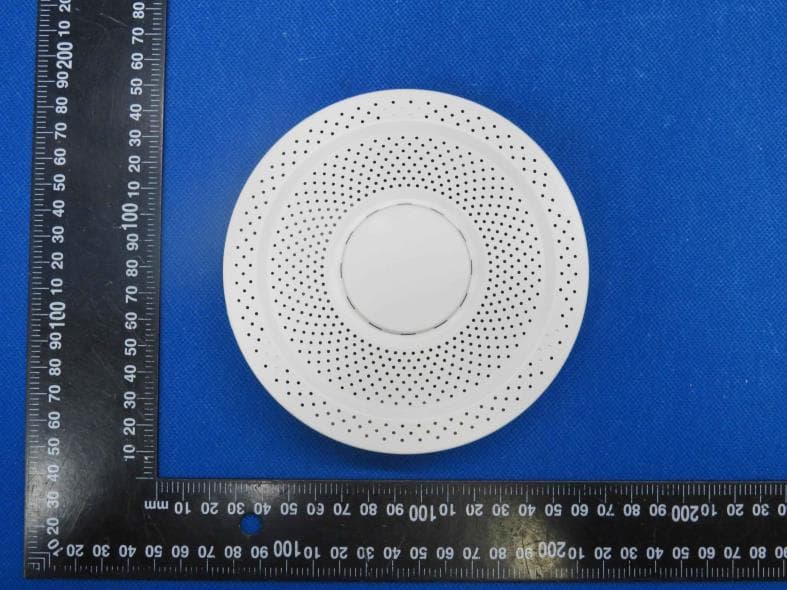
2AMFC-AQS1
Sep 18, 2023Air Quality Sensor
Equipment Class
DTS - Digital Transmission System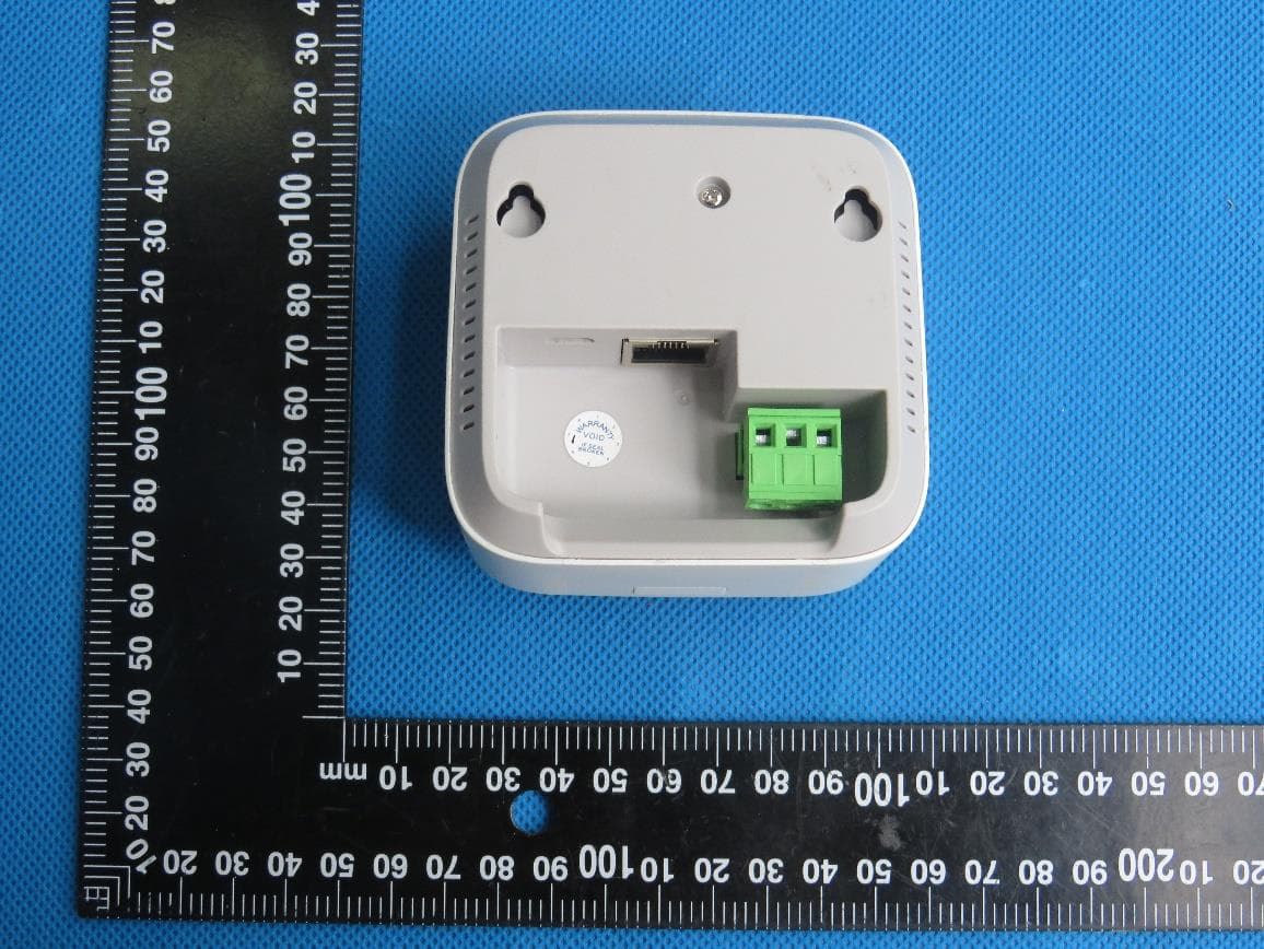
2AMFC-MS1P
May 22, 2021Wireless Motion Sensor
Equipment Class
DSS - Part 15 Spread Spectrum Transmitter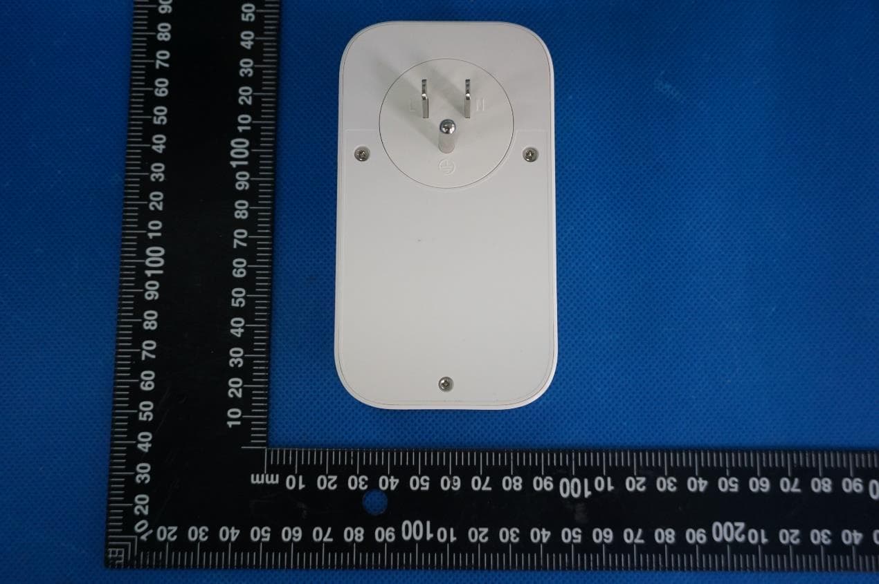
2AMFC-SP1
Dec 28, 2020Ubibot Smart Plug
Equipment Class
DTS - Digital Transmission System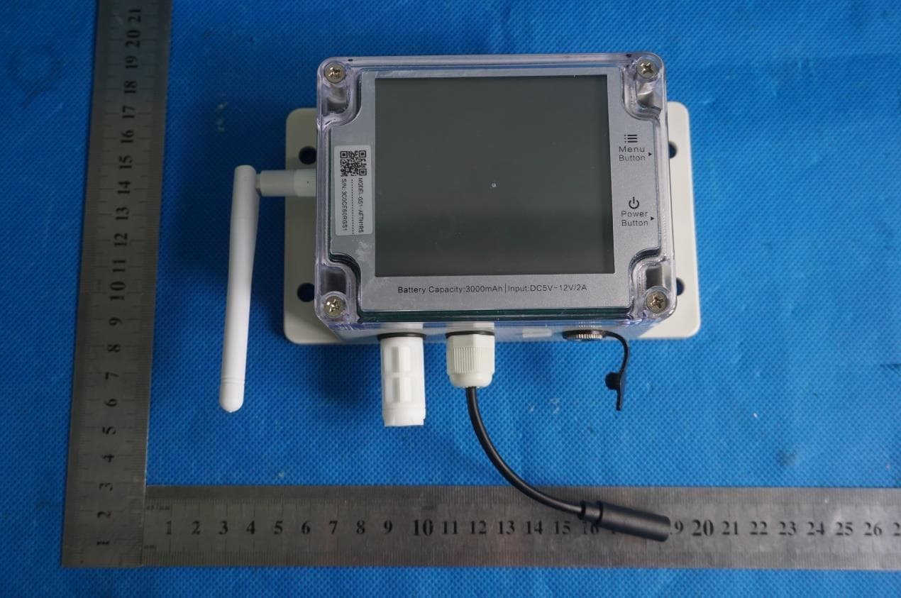
2AMFC-GS1-AETH1RS
Mar 05, 2020Industrial-grade Wireless Smart Multi-Sensor Device GS1
Equipment Class
DTS - Digital Transmission System