2AN62-GM30PLUSGMRS Two Way Radio
SAIN3 LLC
Click to zoom
Application Details
- Equipment Class
- CSR - Scanning Receiver
- Date of Grant
- Aug 14, 2024
- Application Purpose
- Original Equipment
- Date of Application
- Aug 14, 2024
- Equipment Note
- GMRS Two Way Radio
- Frequency Range
- 400.00000000 - 520.00000000
- Company
- SAIN3 LLC
- Country
- United States
Documents & Files
Document Text
Text extracted from the exhibit documents filed with the FCC. Open a document above to read the original.
Users Manual
GM-30 PLUS User Manual GMRS Radio PREFACE Thank you for purchasing GM-30 PLUS Two Way Radio, It is a multitask GMRS transceiver. Combining the latest technology in radio communication along with a sturdy mechanical frame, GM-30 PLUS is the ideal and effective solution for the professionals who need to stay in touch with the working team (in construction sites, buildings, shows, trade fairs or hotels) or for leisure users that just want to keep up with friends and family. IMPORTANT NOTICE To help you ward off bodily injury or property loss that may arise from improper operation, please read all the information carefully before using our products. This contains instructions for safe usage and RF energy awareness and control for compliance with applicable standards and regulation. Safety Information for GMRS Radios Your wireless handheld portable transceiver contains a low power transmitter. When the talk button is pushed, it sends out radio frequency (RF) signals. The device is authorized to operate at a duty factor not to exceed 50%. In August 1996, the Federal Communications Commissions (FCC) adopted RF exposure guidelines with safety levels for handheld wireless devices. FCC Part 15.21 Warning Statement THE GRANTEE IS NOT RESPONSIBLE FOR ANY CHANGES OR MODIFICATIONS NOT EXPRESSLY APPROVED BY THE PARTY RESPONSIBLE FOR COMPLIANCE. SUCH MODIFICATIONS COULD VOID THE USER’S AUTHORITY TO OPERATE THE E Q UI P M E NT. I Table of Contents 1. GETTING STARTED 5.6 Channel mode and Channel selection 1.1 Regulations and Safety Warnings 5.7 Selecting a Zone 1.2 Content of the packaging 5.8 Making a call 1.3 Features and Functions 5.9 Using the Flashlight 2. BATTERY INFORMATION 5.10 Emergency Alert 2.1 Charging the Battery Pack 5.11 FM Radio (FM) 2.2 Charger Supplied 5.12 Monitor 2.3 Use Caution with the Li-ion Battery 5.13 Keypad lock 2.4 How to Charge 5.14 Frequency reversal 2.5 Using the Type-C Charger 5.15 TX repeaters tone 2.6 Battery Maintenance 5.16 Weather Radio/Scan Weather Channel 2.7 Prolonging the life of your battery 6. ADVANCED FEATURES 2.8 How to Store the Battery 6.1 Scanner 3. PREPARATION 6.2 DTMF 3.1 Installing / Removing the Battery 6.3 Amateur Radio Setup 3.2 Installing / Removing the Antenna 7. MAIN MENU FUNCTIONS 3.3 Installing / Removing the Belt Clip 7.1 Basic use 3.4 Installing Additional Speaker/Microphone 7.2 Using short-cuts 4. RADIO OVERVIEW 7.3 Radio Settings 4.1 Status Indications 7.4 GPS function 4.2 LCD icon summary 7.5 Program Channel 4.3 Main keypad controls 7.6 Radio Info 5. BASIC OPERATIONS Appendix A. – Trouble shooting guide 5.1 Power on the radio Appendix B. - Technical Specifications 5.2 Adjusting the volume Appendix C. - Shortcut Menu operations 5.3 Main Band/Sub Band Switch Appendix D. - DCS Table 5.4 VFO/Channel Switch Appendix E. - CTCSS Table 5.5 Frequency (VFO) mode II 1. GETTING STARTED 1.1 Regulations and Safety Warnings This device complies with Part 15 of the FCC Rules. Operation is subject to the following two conditions: (1) This device may not cause harmful interference. (2) This device must accept any interference received, including interference that may cause undesired operation. Important: Any changes or modifications not expressly approved by the party responsible for compliance could void the user's authority to operate this device. Your radio is set up to transmit a regulated signal on an assigned frequency. It is against the law to alter or adjust the settings inside the radio to exceed those limitations. Any adjustments to your radio must be made by qualified technicians. To be safe and sure: • Never open your radio’s case. • Never change or replace anything in your radio except the battery. Your radio might cause TV or radio interference even when it is operating properly. To determine whether your radio is causing the interference, turn it off. If the interference goes away, your radio is causing it. Try to eliminate the interference by moving your radio away from the receiver. If you cannot eliminate the interference, the FCC requires that you stop using the radio. Hazardous Environments: Do not operate the radio in hazardous environments. Explosion or fire may result. Do not operate the radio near unshielded electrical blasting caps. Under certain conditions, radios can interfere with blasting operations and may cause an explosion. Turn your radio OFF to prevent accidental transmission when in a blasting area or in areas posted: "Turn off two-way radio." Construction crews often use remote control RF devices to set off explosives. Care and Safety: To clean the radio, use a soft cloth dampened with water. Do not use cleaners or solvents because they can harm the body of the unit and leak inside, causing permanent damage. Use a dry, lint-free cloth to clean the battery contacts. -1- RF Exposure Information WARNING! Read this information before using the radio. In August 1996 the Federal Communications Commission (FCC) of the United States with its action in Report and Order FCC 96-326 adopted an updated safety standard for human exposure to radio frequency electromagnetic energy emitted by FCC regulated transmitters. Those guidelines are consistent with the safety standard previously set by both U.S. and international standards bodies. The design of the radio complies with the FCC guidelines and these international standards. Never allow children to operate the radio without adult supervision and the knowledge of the following guidelines. WARNING! It is up to the user to properly operate this radio transmitter to insure safe operation. Please adhere to the following: Use only the supplied or an approved antenna. Unauthorized antennas, modifications, or attachments could impair call quality, damage the radio, or result in violation of FCC regulations. Do not use the radio with a damaged antenna. If a damaged antenna comes into contact with the skin, a minor burn may result. Please contact your local dealer for a replacement antenna. Hand-h…
Text truncated - open the document above for the full version.
Attestation Statements
SAIN3 LLC 36 Berkley Drive Newark Delaware United States 19702 Federal Communications Commission Authorization and Evaluation Division 7435 Oakland Mills Road Columbia, MD 21046 USA Date: Aug. 06, 2024 Ref: Attestation Statements Part 2.911(d)(5)(i) Filing FCC ID: 2AN62-GM30PLUS FRN: 0026960740 SAIN3 LLC (“the applicant”) certifies that the equipment for which authorization is sought is not “covered” equipment prohibited from receiving an equipment authorization pursuant to section 2.903 of the FCC rules. Sincerely, (Applicant signature) Damon Cheng
Attestation Statements
SAIN3 LLC 36 Berkley Drive Newark Delaware United States 19702 Federal Communications Commission Authorization and Evaluation Division 7435 Oakland Mills Road Columbia, MD 21046 USA Date: Aug. 06, 2024 Ref: Attestation Statements Part 2.911(d)(5)(ii) Filing FCC ID: 2AN62-GM30PLUS FRN: 0026960740 SAIN3 LLC (“the applicant”) certifies that, as of the date of the filing of the application, the applicant is not identified on the Covered List as an entity producing “covered” equipment. Sincerely, Sincerely, (Applicant signature) Damon Cheng
Attestation Statements
SAIN3 LLC 36 Berkley Drive Newark Delaware United States 19702 2.911 (d)(7)USA Agent v1.2 Section 2.911(d)(7) USA Agent for Service of Process FCC ID: 2AN62-GM30PLUS 2.911(d)(7) USA Designated Agent for Service of Process We, SAIN3 LLC (“the applicant”) designate SAIN3 LLC NOTE1 for the purpose of accepting service of process on behalf of the applicant. Applicant consent: We Acknowledge our consent to accept service of process in the United States for matters related to the applicable equipment, and at the physical U.S. address and email address of the designated agent and acknowledge our acceptance of our obligation to maintain an agent for service of process in the United States for no less than one year after either the grantee has permanently terminated all marketing and importation of the applicable equipment within the U.S., or the conclusion of any Commission-related administrative or judicial proceeding involving the equipment, whichever is later. Agent obligation: We Acknowledge our obligation to accept service of process in the United States for matters related to the applicable equipment at our physical U.S. address and email address for no less than one year after either the grantee has permanently terminated all marketing and importation of the applicable equipment within the U.S., or the conclusion of any Commission-related administrative or judicial proceeding involving the equipment, whichever is later. USA Agent & Applicant Name: SAIN3 LLC Address: 36 Berkley Drive Newark Delaware United States 19702 Contact Person: Damon Cheng, President FRN: 0026960740 Tel.: (408) 455-3566 Email: [email protected] Signature: ___________________ Damon Cheng, President Date: Aug. 06, 2024 NOTE 1: An applicant located in the United States may designate itself as the agent for service of process. Reference; Federal Register document 2022-28263 published on 02/06/23 https://www.federalregister.gov/documents/2023/02/06/2022-28263/protecting-against-national-security- threats-to-the-communications-supply-chain-through-the
Cover Letter(s)
SAIN3 LLC 36 Berkley Drive Newark Delaware United States 19702 Date: 2024-08-06 Declaration Letter FEDERAL COMMUNICATIONS COMMISSION Authorization and Evaluation Division 7435 Oakland Mills Road Columbia, MD 21046 Subject: Declaration of compliance to the requirements of §15.121 FCC ID: 2AN62-GM30PLUS Dear Sir/Madam, We declare that, this scanning receiver is incapable of operating (tuning), or readily being altered by the users to operate, within the frequency bands allocated to the Cellular Radiotelephone Service in part 22 of this chapter (cellular telephone bands). This device will not be able to receive transmissions in the cellular telephone bands by means of clipping the leads of, or installing, a simple component such as a diode, resistor or jumper wire; replacing a plug-in semiconductor chip; or programming a semiconductor chip using special access codes or an external device, such as a personal computer. This device is also incapable of converting digital cellular communication transmissions to analog voice audio. This device is designed so that the tuning, control and filtering circuitry is inaccessible. Any attempts to modify the equipment to receive transmissions from the Cellular Radiotelephone Service will render the receiver inoperable. This scanning receiver rejects any signals from the Cellular Radiotelephone Service frequency bands that are 38 dB or lower based upon a 12 dB SINAD measurement. We are aware that the modification of this device to receive transmissions from Cellular Radiotelephone Service frequency bands will be considered to constitute manufacture of such equipment. This includes any individual, individuals, entity or organization that modifies one or more scanners. Any modification to receive transmissions from the Cellular Radiotelephone Service frequency bands voids the certification of the scanning receiver, regardless of the date of manufacture of the original unit. Sincerely Yours, Signature: ___________________________ Contact person: Damon Cheng
Cover Letter(s)
SAIN3 LLC 36 Berkley Drive Newark Delaware United States 19702 Office of Engineering Technology Federal Communications Commission 7435 Oakland Mills Road Columbia, MD 21046 USA Date: Aug. 06, 2024 Subject; Request for Confidentiality FCC ID: 2AN62-GM30PLUS To Whom It May Concern, Pursuant to the provisions of the Commission’s rules Title 47 Sections §0.457 and §0.459, we are requesting the Commission to withhold the following attachment(s) as confidential documents from public disclosure indefinitely. These documents contain detailed system and equipment descriptions and are considered as proprietary information in operation of the equipment. The public disclosure of these documents might be harmful to our company and would give competitors an unfair advantage in the market. Schematic Diagram Block Diagram Operational Description Parts List Tune-up Procedure In additional to above mentioned documents, in order to comply with the marketing regulations in Title 47 CFR §2.803 and the importation rules in Title 47 CFR §2.1204, while ensuring that business sensitive information remains confidential until the actual marketing of newly authorized devices, we request Short Term Confidentiality of the following attachment(s); External Photos Test Setup Photos Internal Photos User Manual For 45 days, pursuant to Public Notice DA 04-1705. OR For 180 days pursuant to KDB 726920 D01. It is our understanding that all measurement test reports, FCC ID label format and correspondence during the certification review process cannot be granted as confidential documents and this information will be available for public review once the grant of equipment authorization is issued. Sincerely, Signature: Name: Damon Cheng Title: President
Cover Letter(s)
Letter of Authorization Company: SAIN3 LLC Address: 36 Berkley Drive Newark Delaware United States 19702 Product Name: GMRS Two Way Radio Model Number(s): GM-30 PLUS Product Description: GMRS Two Way Radio We authorize MiCOM Labs Inc., 575 Boulder Court, Pleasanton, California 94566, USA, to act on our behalf on all matters concerning the certification of above named equipment. We declare that MiCOM Labs Inc. is allowed to forward all information related to the approval and certification of equipment to the regulatory agencies as required and to discuss any issues concerning the approval application. Any and all acts carried out by MiCOM Labs on our behalf shall have the same effect as acts of our own. Signature: Date: Aug. 06, 2024 Name: Damon Cheng Title: President Company: SAIN3 LLC
External Photos
Report No.: AGC05559240701AP02 Page 1 of 5 EXTERNAL PHOTOS All VIEW OF EUT TOP VIEW OF EUT GMRS Antenna Report No.: AGC05559240701AP02 Page 2 of 5 BOTTOM VIEW OF EUT FRONT VIEW OF EUT Report No.: AGC05559240701AP02 Page 3 of 5 BACK VIEW OF EUT LEFT VIEW OF EUT Report No.: AGC05559240701AP02 Page 4 of 5 RIGHT VIEW OF EUT PORT VIEW OF EUT-1 Report No.: AGC05559240701AP02 Page 5 of 5 PORT VIEW OF EUT-2 ****************************************End of Report*************************************
ID Label/Location Info
FCC ID Label Location 30mm*20mm FCC ID: 2AN62-GM30PLUS
Internal Photos
Report No.: AGC05559240701AP02 Page 1 of 10 INTERNAL PHOTOS OPEN VIEW OF EUT (FIGURE 1) OPEN VIEW OF EUT (FIGURE 2) Report No.: AGC05559240701AP02 Page 2 of 10 OPEN VIEW OF EUT (FIGURE 3) INTERNAL VIEW OF EUT (FIGURE 1) Report No.: AGC05559240701AP02 Page 3 of 10 INTERNAL VIEW OF EUT (FIGURE 2) INTERNAL VIEW OF EUT (FIGURE 3) Report No.: AGC05559240701AP02 Page 4 of 10 INTERNAL VIEW OF EUT (FIGURE 4) INTERNAL VIEW OF EUT (FIGURE 5) Report No.: AGC05559240701AP02 Page 5 of 10 INTERNAL VIEW OF EUT (FIGURE 6) INTERNAL VIEW OF EUT (FIGURE 7) Report No.: AGC05559240701AP02 Page 6 of 10 INTERNAL VIEW OF EUT (FIGURE 8) INTERNAL VIEW OF EUT (FIGURE 9) Report No.: AGC05559240701AP02 Page 7 of 10 INTERNAL VIEW OF EUT (FIGURE 10) INTERNAL VIEW OF EUT (FIGURE 11) Report No.: AGC05559240701AP02 Page 8 of 10 INTERNAL VIEW OF EUT (FIGURE 12) INTERNAL VIEW OF EUT (FIGURE 13) Report No.: AGC05559240701AP02 Page 9 of 10 INTERNAL VIEW OF EUT (FIGURE 14) INTERNAL VIEW OF EUT (FIGURE 15) Report No.: AGC05559240701AP02 Page 10 of 10 INTERNAL VIEW OF EUT (FIGURE 16) INTERNAL VIEW OF EUT (FIGURE 17) ****************************************End of Report*************************************
RF Exposure Info
Page 1 of 26 FCC Test Report Report No.: AGC05559240701FE01 FCC ID 2AN62-GM30PLUS APPLICATION PURPOSE : Original Equipment PRODUCT DESIGNATION : GMRS Two Way Radio BRAND NAME : Radioddity MODEL NAME : GM-30 PLUS APPLICANT : SAIN3 LLC DATE OF ISSUE : Jul. 26, 2024 STANDARD(S) : FCC Part 15 Subpart B REPORT VERSION : V1.0 Attestation of Global Compliance (Shenzhen) Co., Ltd Report No.: AGC05559240701FE01 Page 2 of 26 Report Revise Record Report Version Revise Time Issued Date Valid Version Notes V1.0 / Jul. 26, 2024 Valid Initial Release Report No.: AGC05559240701FE01 Page 3 of 26 Table of Contents 1. General Information ........................................................................................................................................ 4 2. Product Information ........................................................................................................................................ 5 2.1 Product Technical Description ................................................................................................................... 5 2.2 Auxiliary Surrounding Description ............................................................................................................. 5 2.2 Test Methodology ...................................................................................................................................... 6 2.3 Description of Test Modes ......................................................................................................................... 6 3. Test Environment ............................................................................................................................................ 7 3.1 Address of The Test Laboratory ................................................................................................................ 7 3.2 Test Facility ................................................................................................................................................ 7 3.3 Environmental Conditions ......................................................................................................................... 8 3.4 Measurement Uncertainty ......................................................................................................................... 8 3.5 List of Equipment Used ............................................................................................................................. 9 4. Summary of Test Results ............................................................................................................................. 10 5. Radiated Emission Measurements .............................................................................................................. 11 5.1 Provisions Applicable .............................................................................................................................. 11 5.2 Measurement Setup ................................................................................................................................ 11 5.3 Measurement Procedure ......................................................................................................................... 12 5.4 Measurement Resul ................................................................................................................................ 13 6. Conducted Emission Measurements .......................................................................................................... 17 6.1 Provisions Applicable .............................................................................................................................. 17 6.2 Measurement Setup ................................................................................................................................ 17 6.3 Measurement Procedure ......................................................................................................................... 18 6.4 Measurement Result ............................................................................................................................... 19 7. Antenna Conducted Power for Receivers .................................................................................................. 21 7.1 Provisions Applicable .............................................................................................................................. 21 7.2 Measurement Setup ................................................................................................................................ 21 7.3 Measurement Procedure ......................................................................................................................... 21 7.4 Measurement Result ............................................................................................................................... 22 8. Scanning Receivers and Frequency Converters Used with Scanning Receivers ................................. 24 8.1 Provisions Applicable .............................................................................................................................. 24 8.2 Measurement Setup ................................................................................................................................ 24 8.3 Measurement Procedure ......................................................................................................................... 24 8.4 Measurement Result ............................................................................................................................... 25 Appendix I: Photographs of Test Setup .......................................................................................................... 26 Appendix II: Photographs of Test EUT ........................................................................................................... 26 Report No.: AGC05559240701FE01 Page 4 of 26 1. General Info…
Text truncated - open the document above for the full version.
Test Report
Page 1 of 26 FCC Test Report Report No.: AGC05559240701FE01 FCC ID 2AN62-GM30PLUS APPLICATION PURPOSE : Original Equipment PRODUCT DESIGNATION : GMRS Two Way Radio BRAND NAME : Radioddity MODEL NAME : GM-30 PLUS APPLICANT : SAIN3 LLC DATE OF ISSUE : Jul. 26, 2024 STANDARD(S) : FCC Part 15 Subpart B REPORT VERSION : V1.0 Attestation of Global Compliance (Shenzhen) Co., Ltd Report No.: AGC05559240701FE01 Page 2 of 26 Report Revise Record Report Version Revise Time Issued Date Valid Version Notes V1.0 / Jul. 26, 2024 Valid Initial Release Report No.: AGC05559240701FE01 Page 3 of 26 Table of Contents 1. General Information ........................................................................................................................................ 4 2. Product Information ........................................................................................................................................ 5 2.1 Product Technical Description ................................................................................................................... 5 2.2 Auxiliary Surrounding Description ............................................................................................................. 5 2.2 Test Methodology ...................................................................................................................................... 6 2.3 Description of Test Modes ......................................................................................................................... 6 3. Test Environment ............................................................................................................................................ 7 3.1 Address of The Test Laboratory ................................................................................................................ 7 3.2 Test Facility ................................................................................................................................................ 7 3.3 Environmental Conditions ......................................................................................................................... 8 3.4 Measurement Uncertainty ......................................................................................................................... 8 3.5 List of Equipment Used ............................................................................................................................. 9 4. Summary of Test Results ............................................................................................................................. 10 5. Radiated Emission Measurements .............................................................................................................. 11 5.1 Provisions Applicable .............................................................................................................................. 11 5.2 Measurement Setup ................................................................................................................................ 11 5.3 Measurement Procedure ......................................................................................................................... 12 5.4 Measurement Resul ................................................................................................................................ 13 6. Conducted Emission Measurements .......................................................................................................... 17 6.1 Provisions Applicable .............................................................................................................................. 17 6.2 Measurement Setup ................................................................................................................................ 17 6.3 Measurement Procedure ......................................................................................................................... 18 6.4 Measurement Result ............................................................................................................................... 19 7. Antenna Conducted Power for Receivers .................................................................................................. 21 7.1 Provisions Applicable .............................................................................................................................. 21 7.2 Measurement Setup ................................................................................................................................ 21 7.3 Measurement Procedure ......................................................................................................................... 21 7.4 Measurement Result ............................................................................................................................... 22 8. Scanning Receivers and Frequency Converters Used with Scanning Receivers ................................. 24 8.1 Provisions Applicable .............................................................................................................................. 24 8.2 Measurement Setup ................................................................................................................................ 24 8.3 Measurement Procedure ......................................................................................................................... 24 8.4 Measurement Result ............................................................................................................................... 25 Appendix I: Photographs of Test Setup .......................................................................................................... 26 Appendix II: Photographs of Test EUT ........................................................................................................... 26 Report No.: AGC05559240701FE01 Page 4 of 26 1. General Info…
Text truncated - open the document above for the full version.
Test Setup Photos
Report No.: AGC05559240701AP03 Page 1 of 2 TEST SETUP PHOTOS RADIATED EMISSION TEST SETUP BELOW 1GHz RADIATED EMISSION TEST SETUP ABOVE 1GHz Report No.: AGC05559240701AP03 Page 2 of 2 AC POWER LINE CONDUCTED TEST SETUP ****************************************End of Report*************************************
Contact Information
Applicant
Damon Cheng(President)
Technical Contact
Test Firm
Attestation of Global Compliance (Shenzhen) Co., LDoris Li
[email protected]+86-755-25234088
Technical Specifications
| # | Rule Parts | Frequency Range | Power Output |
|---|---|---|---|
| 6 | 15B | 400 MHz - 520 MHz | - |
Other Applications from SAIN3 LLC
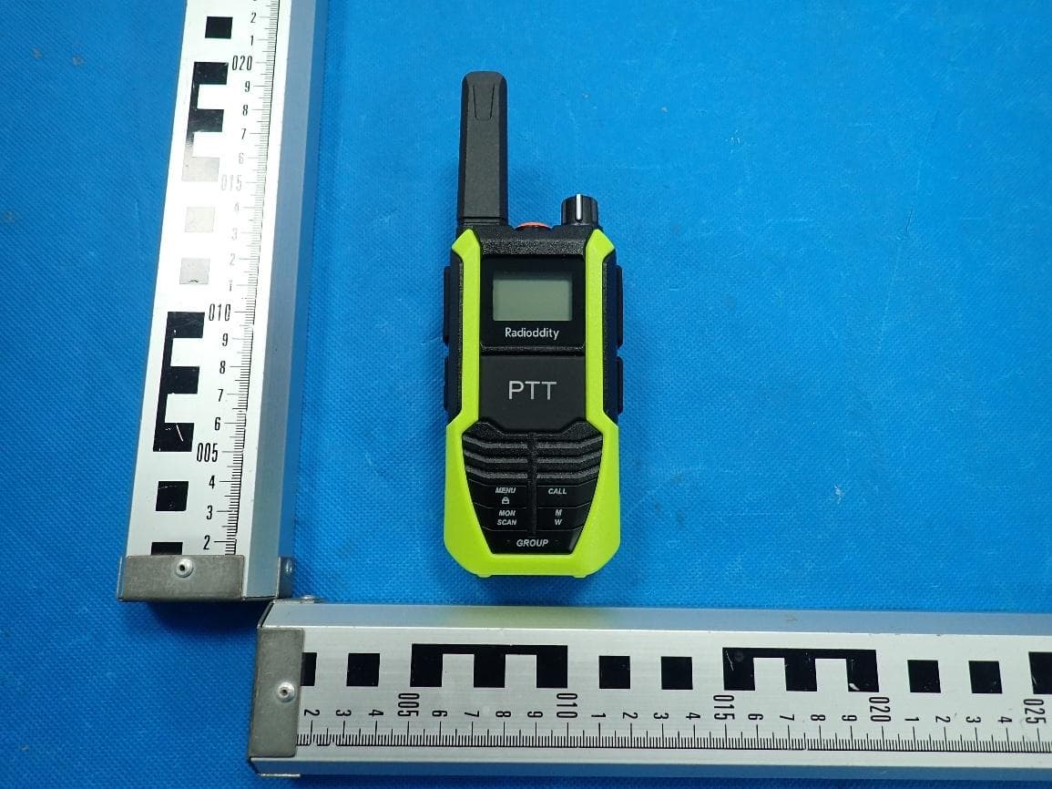
2AN62-HD2
Aug 27, 2026Two Way Radio
Equipment Class
FRF - Part 95 Family Radio Face Held Transmitter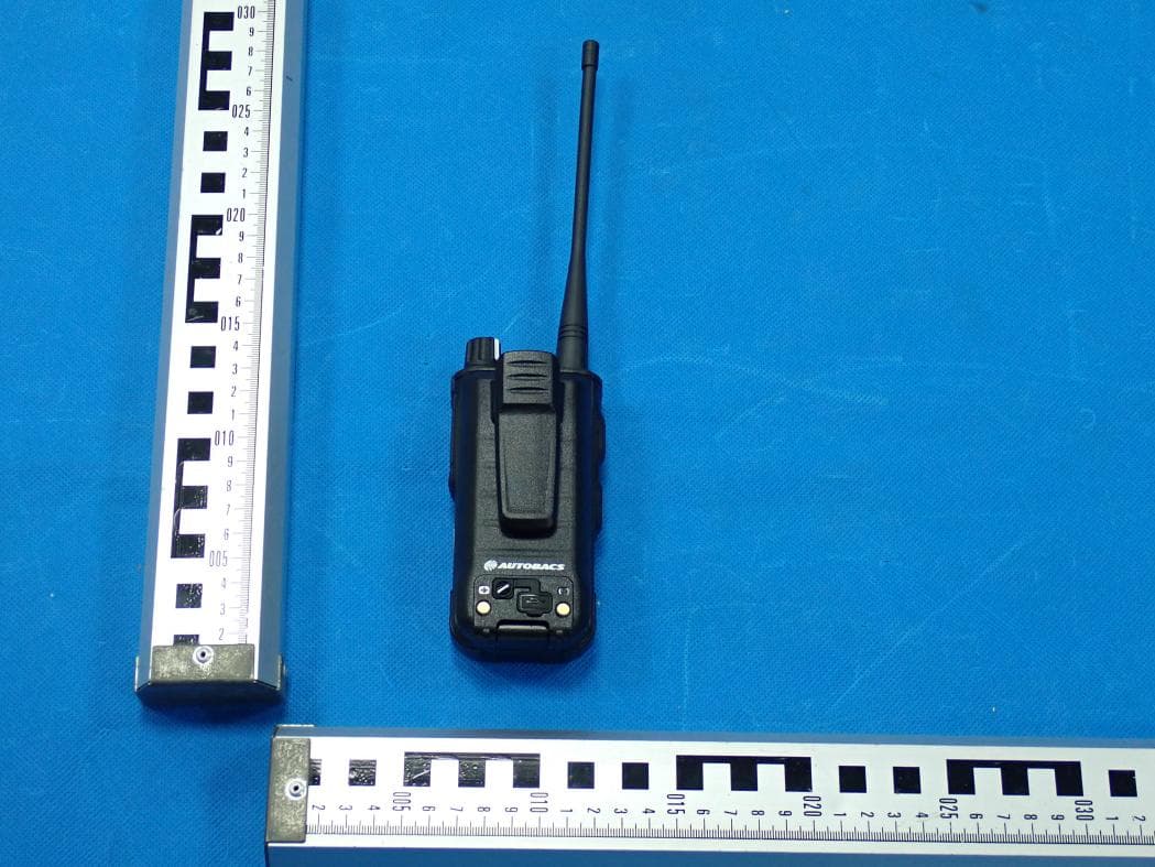
2AN62-X1PRO
Jun 23, 2026GMRS Radio
Equipment Class
TNF - Licensed Non-Broadcast Transmitter Held to Face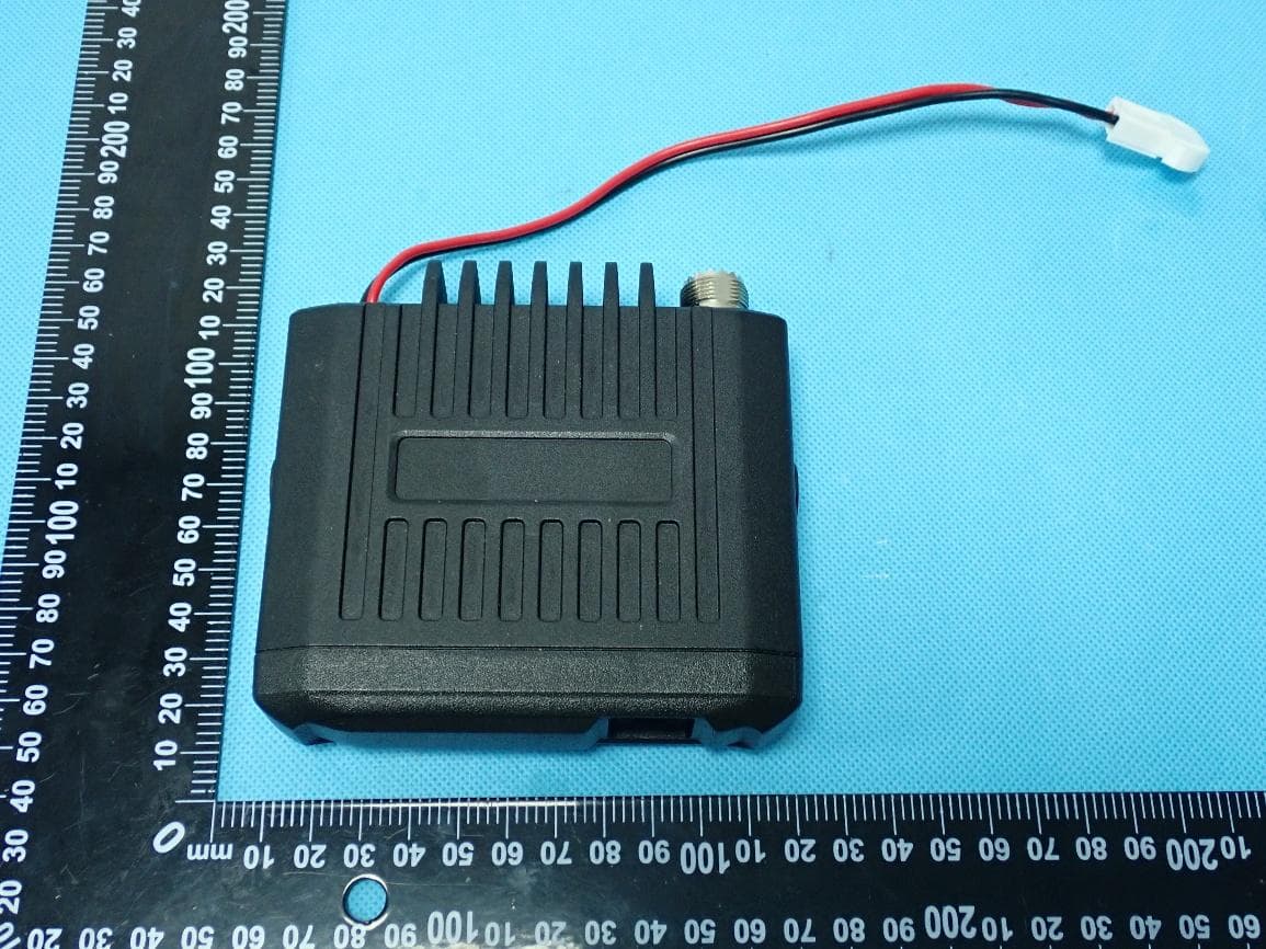
2AN62-UB15G
May 29, 2026Mobile Radio
Equipment Class
TNF - Licensed Non-Broadcast Transmitter Held to Face
2AN62-DB35UV
Apr 09, 2026Mobile Radio
Equipment Class
CSR - Scanning Receiver
2AN62-DB35G
Mar 27, 2026Mobile Radio
Equipment Class
CSR - Scanning Receiver