2AN62-HD2Two Way Radio
SAIN3 LLC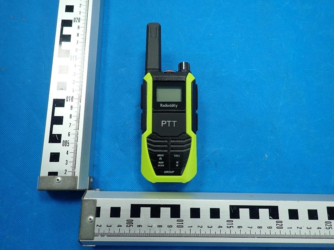
Click to zoom
Application Details
- Equipment Class
- FRF - Part 95 Family Radio Face Held Transmitter
- Date of Grant
- Aug 27, 2026
- Application Purpose
- Original Equipment
- Equipment Note
- Two Way Radio
- Frequency Range
- 462.55000000 - 462.72500000
- Company
- SAIN3 LLC
- Country
- United States
Documents & Files
Document Text
Text extracted from the exhibit documents filed with the FCC. Open a document above to read the original.
Users Manual
Radioddity HD-2 User Manual Table of Contents 1. Product Overview 2. Screen Layout 3. Basic Functions 3.1 Power Switch 3.2 Volume Adjustment 3.3 Channel Selection 3.4 Vibration Alert (On/Off) 3.5 Menu Functions 3.6 Talkback Function 4. Advanced Functions 4.1 Voice Prompt On / Off 4.2 Low Battery Warning 4.3 Time-Out Timer (TOT) 4.4 VOX Voice Activation Function 4.5 High / Low Power Selection 4.6 Whisper Mode 4.7 One-Click Mute Function 4.8 Emergency Power Output 4.9 Power Saving Function 4.10 Tail Tone Elimination Function 4.11 Analog Sub-audio (CTCSS) / Digital Sub-audio (DCS) 4.12 NOAA Reception 4.13 Call Tone 4.14 Scan Function 4.15 Transmission End Tone 4.16 SOS Function 4.17 External Headset Specification 4.18 One-key Group Call 4.19 Vibration Alert Function 5. Technical Specifications 6. Annex 1: Default Frequencies (FRS 22 Channels) 1.Product Overview 1. Antenna: Transmits and receives radio signals. 2. SOS Alarm Button: Press and hold to activate the emergency SOS alarm. 3. Volume / Power Knob: Rotate to turn the radio on/off and adjust the volume level. 4. Side PTT (Push-To-Talk) Button: Press to transmit. 5. Headset Jack: Connects an external headset accessory. 6. LCD Display: Displays channel, power level, and other status information. 7. PF1 (▲) Up Button: Navigates upward through menu options and adjusts settings. 8. PF2 (▼) Down Button: Navigates downward through menu options and adjusts settings. 9. Type-C Charging Port: Used for charging the radio and reverse charging (power output). 10. Front PTT (Push-To-Talk) Button: Press to transmit. 11. Menu Button: Short press to access and cycle through menu settings; long press to lock the keypad. 12. CALL Button: Short press to send a call tone; long press to activate the weather forecast. 13. Monitor / Scan Button: Short press to monitor the channel (listen for activity); long press to start scanning. Mute / Whisper Button: Short press for one-key mute (all incoming signals silenced); long press to activate whisper mode (transmit at 20% normal volume for covert operation). 15.Group Call Button: Press and hold to initiate a group call transmission. 2.Screen Layout 1. Group Call Enabled (indicated by "2CH") 2. Scan 3. High Power 4. VOX (Voice-Activated Transmission) 5. Battery Level 6. Mute 7. Transmit Indicator (Arrow + Signal Animation) 8. Receive Indicator (Arrow + Signal Animation) 9. NOAA Weather 10. Keypad Lock 3.Basic Functions 3.1 Power Switch Power On: Rotate the Power/Volume Control Knob clockwise to turn on the radio. A click will be heard, followed by a startup tone, and the current channel will be announced. Power Off: Rotate the Power/Volume Control Knob counterclockwise until a click is heard, indicating the radio is powered off. 3.2 Volume Adjustment Rotate the Power/Volume Control Knob clockwise to increase the volume, or counterclockwise to decrease the volume. 3.3 Channel Selection In standby mode, press the 【MENU】 key once. The channel number will begin flashing. Press 【▲】 or 【▼】 to select a channel. If voice prompts are enabled, the selected channel number will be announced. Note: Each press changes the channel by one step in a continuous loop: Pressing 【▲】: 1→22→1→22... pressing 【▼】: 22→1→22→1... 3.4 Vibration Alert (On/Off) In standby mode, press the 【MENU】 key eight times to access the vibration setting. The LCD will display "UI". Press the 【▲】 or 【▼】 side key to turn the function ON or OFF. ON = Vibration alert enabled; OF = Vibration alert disabled. 3.5 Menu Functions Menu 1: Channel Switching Menu 2: CTCSS/DCS Tone Switching Menu 3: Call Alert Switching Menu 4: VOX Sensitivity Adjustment Menu 5: High / Low Power Switching Menu 6: Scan Switch Menu 7: Talk End Tone Switch Menu 8: Vibration Alert Switch Menu 9: Off-Network Switch 3.6 Transmit Function Press and hold the PTT button to transmit. The indicator will light up. Speak normally into the microphone. Release the PTT button to return to receive mode. Keep the microphone about 3–8 cm from your mouth while speaking. Note: If the receiving radio has vibration alert enabled, it will vibrate for about 5 seconds at the start of the first transmission. During this time, audio will not be received. Wait approximately 5 seconds before speaking to ensure your message is heard. 4.Advanced Function 4.1 Voice Prompt On / Off The radio supports voice prompts that announce the current channel, making operation easier in low-light conditions. This function can be enabled or disabled via PC programming software. 4.2 Low Battery Warning The low battery alert will activate when the battery requires charging or replacement. If voice prompts are enabled, the radio will announce “Please change battery” every 120 seconds. If voice prompts are disabled, three short beeps will sound as a reminder to recharge or replace the battery. 4.3 Time-Out Timer (TOT) The Time-Out Timer limits continuous transmission time to prevent channel overuse. The TOT duration can be set via PC programming software from 15 to 600 seconds, in 15-second increments. When the preset time is reached, transmission will stop automatically and a warning tone will sound. Release the PTT button to stop the alert. Press PTT again to resume transmission. Default TOT is 3 minutes 30 seconds (210 seconds) 4.4 VOX Voice Activation The VOX function allows the radio to transmit automatically when your voice is detected. Operation: In standby mode, press the 【MENU】 key four times until the VOX level flashes. Use the 【▲】 / 【▼】 keys to adjust the level (0–9). Press 【MENU】 again to save. Level 0: VOX off Level 9: Highest sensitivity Notes The higher the VOX level, the less sound is required to trigger transmission VOX delay time determines how long the radio remains in transmit mode after you stop speaking. It can be set via PC software to 0.5 / 1 / 1.5 / 2 / 2.5 / 3 seconds. 4.5 High / Low Power Switching Channels 1–7 and 15–22 support selectable transmit power levels. Each channel can be configured to High Power or …
Text truncated - open the document above for the full version.
Attestation Statements
The information provided in this letter is based on the referenced rule parts of Title 47 of the CFR as well as KDB 986446 D01. An expiration date for this letter does not exist. In case the U.S. agent changes, the grantee is obligated to notify the FCC within 30 days via the granting TCB. 48_[model] US_Agent_2.911(d)(7) - U, V05 SAIN3 LLC 36 Berkley Drive Newark, DE 19702 United States Federal Communications Commission Authorization and Evaluation Division Equipment Authorization Branch 7435 Oakland Mills Road Columbia, MD 21046 Date: Aug. 26, 26 U.S. Agent Designation SAIN3 LLC acknowledges their consent for the following contact located in the United States to act as their agent for service of process for the equipment for which authorization is sought (FCC ID: 2AN62-HD2) Name and company of U.S. agent: GLOCERTS TECHNOLOGY INC Physical U.S. address of agent: 19784 SUNKISSED RIDGE DR, RIVERSIDE, CA 92507 FRN of U.S. agent: 0036339737 Email address of U.S. agent: [email protected] Telephone of U.S.agent: (626) 588-8039 GLOCERTS TECHNOLOGY INC acknowledges their obligation to accept service of process on behalf of SAIN3 LLC. SAIN3 LLC with the FRN [0026960740] accepts its obligation to maintain an agent for service of process in the United States for no less than 1 year after either the grantee has permanently terminated all marketing and importation of the applicable equipment within the U.S., or the conclusion of any Commission-related administrative or judicial proceeding involving the equipment, whichever is later. By signing this form, we confirm the above and that we are aware of the application requirements listed under § 2.911(d)(7). The information provided in this letter is based on the referenced rule parts of Title 47 of the CFR as well as KDB 986446 D01. An expiration date for this letter does not exist. In case the U.S. agent changes, the grantee is obligated to notify the FCC within 30 days via the granting TCB. Sincerely, Signature Signature Damon Cheng Huiying Fan President Director SAIN3 LLC GLOCERTS TECHNOLOGY INC
External Photos
Report No.: TZ0413260501PH02 Page 1 of 3 External Photographs of EUT External Photo 1 External Photo 2 Report No.: TZ0413260501PH02 Page 2 of 3 External Photo 3 External Photo 4 Report No.: TZ0413260501PH02 Page 3 of 3 External Photo 5 External Photo 6
ID Label/Location Info
The size of the label is 15mm*10mm with White forecolor. The size of the logo is 5mm*5mm. FCC ID: 2AN62-HD2
Internal Photos
Report No.: TZ0289260601PH03 Page 1 of 12 Internal Photographs of EUT Internal Photo 1 Internal Photo 2 Report No.: TZ0289260601PH03 Page 2 of 12 Internal Photo 3 Internal Photo 4 Report No.: TZ0289260601PH03 Page 3 of 12 Internal Photo 5 Internal Photo 6 Report No.: TZ0289260601PH03 Page 4 of 12 Internal Photo 7 Internal Photo 8 Report No.: TZ0289260601PH03 Page 5 of 12 Internal Photo 9 Internal Photo 10 Report No.: TZ0289260601PH03 Page 6 of 12 Internal Photo 11 Internal Photo 12 Report No.: TZ0289260601PH03 Page 7 of 12 Internal Photo 13 Internal Photo 14 Report No.: TZ0289260601PH03 Page 8 of 12 Internal Photo 15 Internal Photo 16 Report No.: TZ0289260601PH03 Page 9 of 12 Internal Photo 17 Internal Photo 18 Report No.: TZ0289260601PH03 Page 10 of 12 Internal Photo 19 Internal Photo 20 Report No.: TZ0289260601PH03 Page 11 of 12 Internal Photo 21 Internal Photo 22 Internal antenna Report No.: TZ0289260601PH03 Page 12 of 12 Internal Photo 23 Internal Photo 24
RF Exposure Info
Page 1 of 18 CALIBRATION DATA PROBE CALIBRATION DATA Page 2 of 18 Page 3 of 18 Page 4 of 18 Page 5 of 18 Page 6 of 18 Page 7 of 18 Page 8 of 18 Page 9 of 18 Page 10 of 18 DAE CALIBRATION DATA Page 11 of 18 Page 12 of 18 Page 13 of 18 DIPOLE CALIBRATION DATA Page 14 of 18 Page 15 of 18 Page 16 of 18 Page 17 of 18 Page 18 of 18
RF Exposure Info
Page 1 of 43 SAR Test Report Report No.: AGC10211260505FH01 FCC ID : 2AN62-HD2 PRODUCT DESIGNATION : Two Way Radio BRAND NAME : Radioddity MODEL NAME : HD-2 APPLICANT : SAIN3 LLC DATE OF ISSUE : Jul. 16, 2026 STANDARD(S) : IEC/IEEE 62209-1528:2020 FCC 47 CFR Part 2§2.1093 IEEE Std C95.1 ™-2019 REPORT VERSION : V1.0 Attestation of Global Compliance(Shenzhen) Co., Ltd. Report No.: AGC10211260505FH01 Page 2 of 43 Report Revise Record Report Version Revise Time Issued Date Valid Version Notes V1.0 / Jul. 16, 2026 Valid Initial Release Report No.: AGC10211260505FH01 Page 3 of 43 Test Report Applicant Name SAIN3 LLC Applicant Address 36 Berkley Drive Newark, DE 19702 United States Manufacturer Name SAIN3 LLC Manufacturer Address 36 Berkley Drive Newark, DE 19702 United States Factory Name SAIN3 LLC Factory Address 36 Berkley Drive Newark, DE 19702 United States Product Designation Two Way Radio Brand Name Radioddity Test Model HD-2 Series Model N/A Declaration of Difference N/A EUT Voltage DC 3.7V Applicable Standard IEC/IEEE 62209-1528:2020 FCC 47 CFR Part 2§2.1093 IEEE Std C95.1 ™-2019 Date of receipt of test item Apr. 30, 2026 Test Date May 04, 2026 Report Template AGCRT- US -PTT/SAR (2021-04-20) Note: The results of testing in this report apply to the product/system which was tested only. Prepared By Bibo Zhang (Project Engineer) Jul. 16, 2026 Reviewed By Jack Gui (Reviewer) Jul. 16, 2026 Approved By Angela Li (Authorized Officer) Jul. 16, 2026 Report No.: AGC10211260505FH01 Page 4 of 43 TABLE OF CONTENTS 1. SUMMARY OF MAXIMUM SAR VALUE ......................................................................................................... 5 2. GENERAL INFORMATION ............................................................................................................................... 6 2.1. EUT DESCRIPTION......................................................................................................................................... 6 3. SAR MEASUREMENT SYSTEM ........................................................................................................................ 7 3.1. THE DASY5 SYSTEM USED FOR PERFORMING COMPLIANCE TESTS CONSISTS OF FOLLOWING ITEMS .................... 7 3.2. DASY5 E-FIELD PROBE ................................................................................................................................. 8 3.3. DATA ACQUISITION ELECTRONICS DESCRIPTION ............................................................................................... 8 3.4. ROBOT .......................................................................................................................................................... 9 3.5. LIGHT BEAM UNIT .......................................................................................................................................... 9 3.6. DEVICE HOLDER .......................................................................................................................................... 10 3.7. MEASUREMENT SERVER ............................................................................................................................... 10 3.8. PHANTOM ................................................................................................................................................. 11 4. SAR MEASUREMENT PROCEDURE ............................................................................................................ 12 4.1. SPECIFIC ABSORPTION RATE (SAR) .............................................................................................................. 12 4.2. SAR MEASUREMENT PROCEDURE ................................................................................................................ 13 5. TISSUE SIMULATING LIQUID ....................................................................................................................... 16 5.1. THE COMPOSITION OF THE TISSUE SIMULATING LIQUID..................................................................................... 16 5.2. TISSUE DIELECTRIC PARAMETERS FOR HEAD AND BODY PHANTOMS ............................................................... 16 5.3. TISSUE CALIBRATION RESULT ....................................................................................................................... 17 6. SAR SYSTEM CHECK PROCEDURE ........................................................................................................... 18 6.1. SAR SYSTEM CHECK PROCEDURES ............................................................................................................. 18 6.2. SAR SYSTEM CHECK ................................................................................................................................... 19 7. EUT TEST POSITION ...................................................................................................................................... 20 7.1. BODY WORN POSITION ................................................................................................................................ 20 8. SAR EXPOSURE LIMITS ............................................................................................................................... 21 9. TEST FACILITY .............................................................................................................................................. 22 10. TEST EQUIPMENT LIST .............................................................................................................................. 23 11. MEASUREMENT UNCERTAINTY ................................................................................................................ 24 12. POWER MEASUREMENT ............................................................................................................................ 26 13. TEST RESULTS .................................................................................................…
Text truncated - open the document above for the full version.
RF Exposure Info
Impedance Plot for D450V3-SN:1113 450 Head Calibrated impedance:59.2Ω+0.9jΩ;Measurement impedance: 58.4Ω+3.7jΩ(within 5Ω) Calibrated return loss:-21.5dB;Measurement return loss: -22.5dB (within 20%)
Test Report
Report No.: TZ0413260501FRF19 Page 1 of 38 This publication may be reproduced in whole or in part for non-commercial purposes as long as the Shenzhen Tongzhou Testing Co.,Ltd. is acknowledged as copyright owner and source of the material. Shenzhen Tongzhou Testing Co.,Ltd. takes no responsibility for and will not assume liability for damages resulting from the reader's interpretation of the reproduced material due to its placement and context. The test report apply only to the specific sample(s) tested under stated test conditions. It is not permitted to copy extracts of these test result without the written permission of the test laboratory. TEST REPORT Report Number : TZ0413260501FRF19 Product Name : Two Way Radio Model/Type reference : HD-2 FCC ID : 2AN62-HD2 Prepared for : SAIN3 LLC 36 Berkley Drive Newark, DE 19702 United States Prepared By : Shenzhen Tongzhou Testing Co.,Ltd. 1st Floor, Building 1, Haomai High-tech Park, Huating Road 387, Dalang Street, Longhua, Shenzhen, China Standards : FCC CFR Title 47 Part 95 Subpart B, ANSI C63.26-2015 Date of Test : 2026-05-06 ~ 2026-05-08 Date of Issue : 2026-06-09 Prepared by : Nancy Li Reviewed by : Allen Lai Approved by : Max Zhang (Authorized Officer) Report No.: TZ0413260501FRF19 Page 2 of 38 Page 2 of 38 ** Report Revise Record ** Report Version Revise Time Issued Date Valid Version Notes V1.0 / 2026-06-09 Valid Initial release Report No.: TZ0413260501FRF19 Page 3 of 38 Page 3 of 38 TABLE OF CONTENTS 1. G E N E R A L I N F O R M A T I O N ........................................................ 4 1.1. Client Information ................................................................................................................... 4 1.2. Description of Device (EUT) ................................................................................................... 4 1.3. Wireless Function Tested in this Report .............................................................................. 4 1.4. Description of Test Facility .................................................................................................... 5 1.5. Statement of the Measurement Uncertainty ......................................................................... 5 1.6. Measurement Uncertainty ...................................................................................................... 6 1.7. Description of Test Modes ..................................................................................................... 6 1.8. Frequency of Channels .......................................................................................................... 6 2. T E S T M E T H O D O L O G Y ............................................................ 7 2.1. EUT Configuration .................................................................................................................. 7 2.2. EUT Related Submittal (s) / Grant (s) .................................................................................... 7 2.3. Test Sample ............................................................................................................................. 7 3. S Y S T E M T E S T C O N F I G U R A T I O N .............................................. 8 3.1. Justification ............................................................................................................................. 8 3.2. Special Accessories ............................................................................................................... 8 3.3. Block Diagram/Schematics .................................................................................................... 8 3.4. Equipment Modifications ....................................................................................................... 8 3.5. Test Setup ................................................................................................................................ 8 4. S U M M A R Y O F T E S T R E S U L T S ................................................. 9 5. T E S T R E S U L T ..................................................................... 10 5.1. Frequency Stability ............................................................................................................... 10 5.2. Bandwidth .............................................................................................................................. 13 5.3. Transmitter Power................................................................................................................. 16 5.4. Modulation Characteristics .................................................................................................. 18 5.5. Unwanted Emissions ............................................................................................................ 28 5.6. Antenna Requirements ......................................................................................................... 36 6. L I S T O F M E A S U R I N G E Q U I P M E N T S ......................................... 37 7. T E S T S E T U P P H O T O G R A P H S O F E U T ...................................... 38 8. E X T E R I O R P H O T O G R A P H S O F T H E E U T .................................. 38 9. I N T E R I O R P H O T O G R A P H S O F T H E E U T ................................... 38 Report No.: TZ0413260501FRF19 Page 4 of 38 Page 4 of 38 1. G E N E R A L I N F O R M A T I O N 1.1. Client Information Applicant : SAIN3 LLC Address : 36 Berkley Drive Newark, DE 19702 United States Manufacturer : SAIN3 LLC Address : 36 Berkley Drive Newark, DE 19702 United States 1.2. Description of Device (EUT) Product Name : Two Way Radio Trade Mark : Radioddity Model Number : HD-2 Power Supply : DC 3.7V by battery or DC 5V via USB Type-C port Hardware version : Ver 1.0 Software version : Ver 1.0 1.3. Wireless Function Tested in this Report FRS Band Operation Frequency Range : CH01~CH07: 462.5625~462.7125MHz CH08~CH14: 467.5625~467.…
Text truncated - open the document above for the full version.
Test Setup Photos
Report No.: TZ0413260501PH01 Page 1 of 2 Test Setup Photos of the EUT Radiated Emission Below 1GHz Radiated Emission Above 1GHz Report No.: TZ0413260501PH01 Page 2 of 2 RF Conducted Test
Contact Information
Applicant
Damon Cheng(President)
[email protected]Fax: 408455 3566
Technical Contact
Test Firm
Shenzhen Tongzhou Testing Co., Ltd.Matte He
Technical Specifications
| # | Rule Parts | Frequency Range | Power Output | Emission | Tolerance |
|---|---|---|---|---|---|
| 1 | 95B | 462.5625 MHz - 462.7125 MHz | 1.7865 W | 11K0F3E | 2.5ppm |
| 2 | 95B | 467.5625 MHz - 467.7125 MHz | 305.50 mW | 11K0F3E | 2.5ppm |
| 3 | 95B | 462.55 MHz - 462.725 MHz | 1.7219 W | 11K0F3E | 2.5ppm |
Other Applications from SAIN3 LLC
2AN62-X1PRO
Jun 23, 2026GMRS Radio
Equipment Class
TNF - Licensed Non-Broadcast Transmitter Held to Face
2AN62-UB15G
May 29, 2026Mobile Radio
Equipment Class
TNF - Licensed Non-Broadcast Transmitter Held to Face
2AN62-DB35UV
Apr 09, 2026Mobile Radio
Equipment Class
CSR - Scanning Receiver
2AN62-DB35G
Mar 27, 2026Mobile Radio
Equipment Class
CSR - Scanning Receiver
2AN62-X1
Nov 20, 2025Two Way Radio
Equipment Class
JAV - Other Non-Digital SDoC Devices