Text extracted from the exhibit documents filed with the FCC. Open a document above to read the original.
© Intellion 2026 Page 1/7 Intellion AG Schuppisstrasse 10 9016 St. Gallen Switzerland T 0041-71-280 81 81 E [email protected] www intellion.com User Manual LotTrack LPR Checkpoint (Type: STD) Version: 1.1 Date: May 2026 © Intellion 2026 Page 2/7 Table of Contents 1. Functional Use .............................................................................................................. 3 2. General handling instructions ...................................................................................... 4 3. Compliance Information ............................................................................................... 4 3.1 USA: Regulatory Notes ................................................................................................. 4 3.2 Europe: Declaration of Conformity (DoC) ................................................................... 5 © Intellion 2026 Page 3/7 1. Functional Use The LotTrack LPR Checkpoint RF (following: LPR Checkpoint) identifies an operator at an equipment or tool. To enable the start of the processing of the equipment, the user has to authenticate himself using an RFID tag. The LotTrack Checkpoint reads the ID of the RFID tag and sends the ID to LotTrack Control Suite Software. Additionally, the LotTrack Checkpoint indicates the status of an equipment using several LEDs. Figure 1: LotTrack LPR Checkpoint Technical Specifications of the LotTrack LPR Checkpoint: Connectors Ext1 (input or output) 8 pin connector Power RS422 Ext2 (input or output) 8 pin connector Power RS422 Mini USB Diagnostic use only RFID – HF Transponder / Technology ISO 15693 Frequency 13.56 MHz Transmit Output Power < 1 mW Antenna Type Internal PCB antenna Modulation ASK (amplitude shift keying) Indicators Status LED 1x Red / Green © Intellion 2026 Page 4/7 LED Array 12x RGB Buzzer Energy Power supply External DC Nominal supply voltage 5 V DC Voltage range 4.5 – 5.5 V DC Current consumption Max. 250 mA @ 5 VDC Evironmental Operating temperature 10°C ... +40°C Storage temperature 0°C ... +60°C Physical Dimension 90 x 55 x 15 mm Weight approx. 50 g Material ABS 2. General handling instructions Important Notice: Before starting to use the LPR Checkpoint in the fab, carefully read all general handling and user instructions documented in this section. General terms of use for cleaning, storage and transport of the LPR Checkpoint: The LPR Checkpoint is intended to be solely used indoor when implemented in a fab. Gently wipe the surface using a clean room compliant towel that is moistened with Isopro- panol. Do not spray the Isopropanol directly on the LPR Checkpoint. Do not use sharp devices for cleaning. Do not drop, kick or throw the LPR Checkpoint. Do not hit the LPR Checkpoint against surfaces of e.g. desks, push-cards or equipment, nor impose strong mechanical pressure, e.g. on the antennas. Do not expose the LPR Checkpoint to water or other liquids, varnishes, gases, heat or steam. Do not open the LPR Checkpoint. For storage and transport, only use the recommended storage and transport devices for the LPR Checkpoint. All storage and transport devices shall be kept clean before use; the envi- ronment shall be kept dry. Do not install or place the LPR Checkpoint near sources of strong electromagnetic fields and/or strong ultrasound sources. 3. Compliance Information 3.1 USA: Regulatory Notes This device complies with part 15 of the FCC Rules. Operation is subject to the following two condi- tions: © Intellion 2026 Page 5/7 (1) This device may not cause harmful interference, and (2) this device must accept any interference received, including interference that may cause unde- sired operation. Class B digital device. A digital device that is marketed for use in a residential environment not- withstanding use in commercial, business and industrial environments. Examples of such devices include, but are not limited to, personal computers, calculators, and similar electronic devices that are marketed for use by the general public. This equipment has been tested and found to comply with the limits for a Class B digital device, pursuant to part 15 of the FCC Rules. These limits are designed to provide reasonable protection against harmful interference in a residential installation. This equipment generates, uses and can radiate radio frequency energy and, if not installed and used in accordance with the instructions, may cause harmful interference to radio communications. However, there is no guarantee that inter- ference will not occur in a particular installation. If this equipment does cause harmful interference to radio or television reception, which can be determined by turning the equipment off and on, the user is encouraged to try to correct the interference by one or more of the following measures: - Reorient or relocate the receiving antenna. - Increase the separation between the equipment and receiver. - Connect the equipment into an outlet on a circuit different from that to which the receiver is connected. - Consult the dealer or an experienced radio/TV technician for help. CAUTION: Any changes or modifications not expressly approved by the grantee of this device could void the user's authority to operate the equipment. RF exposure warning This equipment must be installed and operated in accordance with provided instructions and the antenna(s) used for this transmitter must be installed to provide a separation distance of at least 20 cm from all persons and must not be co-located or operating in conjunction with any other antenna or transmitter. End-users and installers must be provide with antenna installation instructions and transmitter operating conditions for satisfying RF exposure compliance. Important: This equipment may only be operated indoors. Operation outdoors is in violation of 47 U.S.C. 301 and could subject the operator to serious legal penalties according to Part 15.517 (f). 3.2 Europe: Declaration of Conformity (DoC) [Na…
Text truncated - open the document above for the full version.
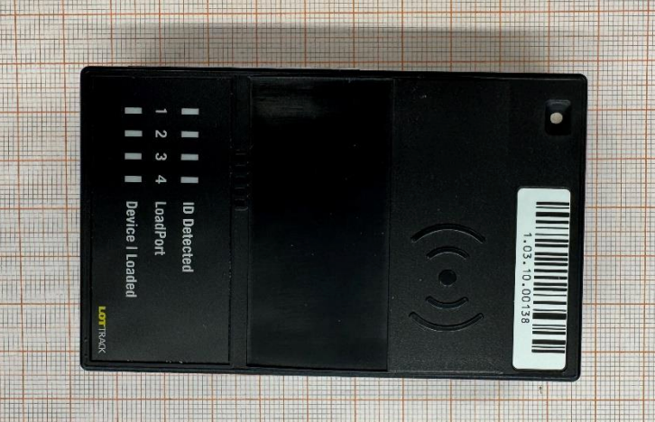
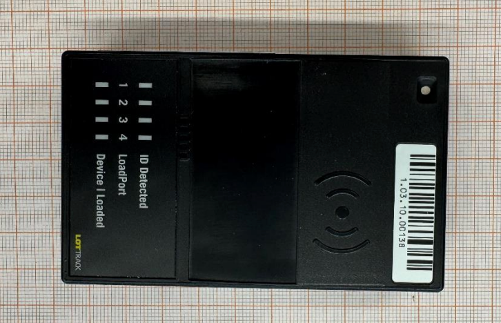
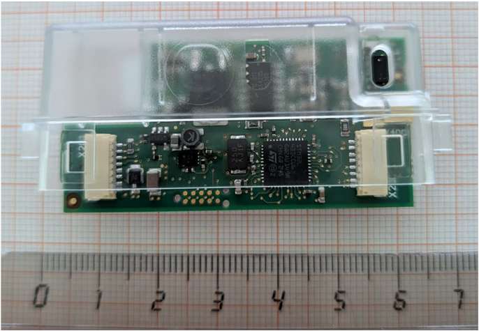
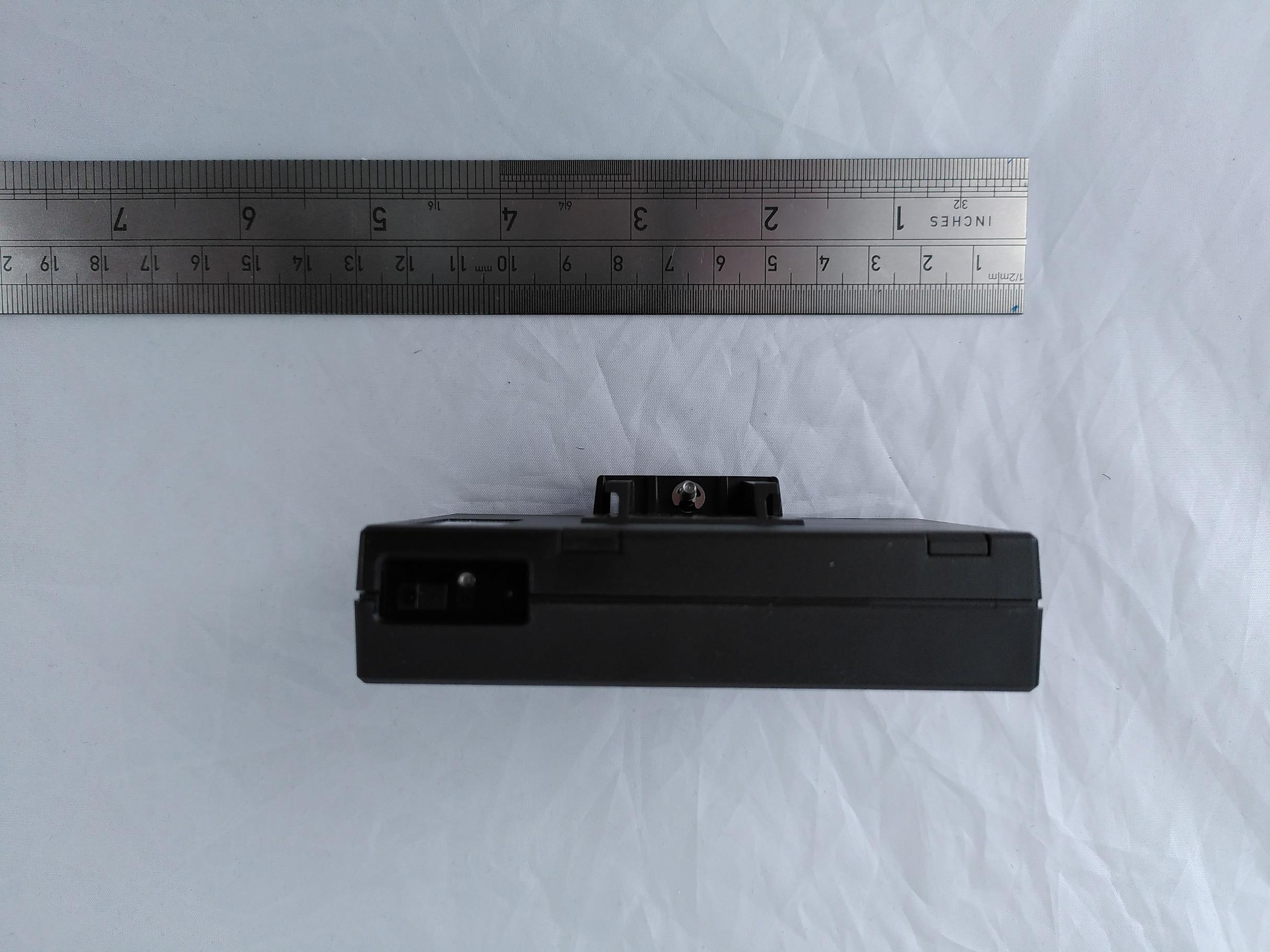
TR no.: 25112121-47671-0 2026-01-07 38 / 47 IBL-Lab GmbH Annex 1 EUT Photographs, external Photo No. 1: EUT A, view 1 Photo No. 2: EUT A, view 2 TR no.: 25112121-47671-0 2026-01-07 39 / 47 IBL-Lab GmbH Photo No. 3: EUT A, view 3 Photo No. 4: EUT B, view 1 TR no.: 25112121-47671-0 2026-01-07 40 / 47 IBL-Lab GmbH Photo No. 5: EUT B, view 2 Photo No. 6: EUT B, view 3 TR no.: 25112121-47671-0 2026-01-07 41 / 47 IBL-Lab GmbH Photo No. 7: EUT C, view 1 Photo No. 8: EUT C, view 2 TR no.: 25112121-47671-0 2026-01-07 42 / 47 IBL-Lab GmbH Photo No. 9: EUT C, view 3 Photo No. 10: AE 1 TR no.: 25112121-47671-0 2026-01-07 43 / 47 IBL-Lab GmbH Photo No. 11: AE 2
Evaluation of product specific Health Aspects Page: 1 of 5 Evaluation Report Product Name: LotTrack LPR Checkpoint Model Name: LPR Checkpoint Type: STD Report No.: Applicant: Intellion AG Prepared by: General Applied Standard(s): EN 62479:2010 CFR47 FCC Part 2: Section 2.1093 FCC KDB Publication 447498 v06 Test Result: complies Intellion AG, Schuppisstrasse 10, 9016 St. Gallen, Switzerland Dr. Kai Millarg Evaluation of product specific Health Aspects Page: 2 of 5 Contents GENERAL 1 Contents 2 Description of EUT 2 Rated Power according to the manufacturer 2 USA Part 3 Limits - USA 3 MPE Calculation Method – USA 3 Evaluation Result 4 Conclusion 4 Europe Part 5 Specification for Evaluation 5 Evaluation Result 5 Conclusion 5 Description of EUT Product Name: LotTrack LPR Checkpoint Model No.: LPR Checkpoint Type: STD Trade Name: LotTrack LPR Checkpoint Frequency Range: 13.56 MHz Working Frequency: Power Supply: 5 V DC Rated Power according to the manufacturer Frequency (MHz) Target Power and Tolerance 13.56 MHz max 1 mW Evaluation of product specific Health Aspects Page: 3 of 5 USA Part Limits - USA Limits for Maximum Permissible Exposure (MPE)/Controlled Exposure Frequency Range(MHz) Electric Field Strength(V/m) Magnetic Field Strength(A/m) Power Density (mW/cm2) Averaging Time (minute) Limits for Occupational/Controlled Exposure 0.3 – 3.0 3.0 – 30 30 – 300 300 – 1500 1500 – 100,000 614 1842/f 61.4 / / 1.63 4.89/f 0.163 / / (100) * (900/f 2 )* 1.0 f/300 5 6 6 6 6 6 Limits for Maximum Permissible Exposure (MPE)/Uncontrolled Exposure Frequency Range(MHz) Electric Field Strength(V/m) Magnetic Field Strength(A/m) Power Density (mW/cm2) Averaging Time (minute) Limits for Occupational/Controlled Exposure 0.3 – 3.0 3.0 – 30 30 – 300 300 – 1500 1500 – 100,000 614 824/f 27.5 / / 1.63 2.19/f 0.073 / / (100) * (180/f 2 )* 0.2 f/1500 1.0 30 30 30 30 30 F=frequency in MHz *=Plane-wave equivalent power density MPE Calculation Method – USA Predication of MPE limit at a given distance as described in Equation on page 18 of OET Bulletin 65, Edition 97-01 S=PG/4πR2 Where: S=power density Evaluation of product specific Health Aspects Page: 4 of 5 P=power input to antenna G=power gain of the antenna in the direction of interest relative to an isotropic radiator R=distance to the center of radiation of the antenna Evaluation Result Modulation Type Target Output power Antenna gain (dBi) Antenna gain (linear) MPE (calculated) MPE (Limit) ASK 1 mW 0.00000001232 mW/cm2 0.979 mW/cm2 Conclusion The device is compliant to the RF Exposure requirements. Evaluation of product specific Health Aspects Page: 5 of 5 Europe Part Specification for Evaluation EN 62479 sets force the basic restrictions related to human exposure to electromagnetic fields. Table A.1 in Annex A of the standard lists example values of SAR-based output power examinations P max for some cases as described by ICNIRP. An excerpt of the table is shown below. Guideline SAR limit, SAR max [W/kg] Averaging mass m [g] Pmax [mW] Exposure tier Regio of Body ICNIRP 2 10 20 General population Head and trunk Evaluation Result The antenna power of the EUT according to test report no.: is measured as: The manufacturer declares the maximum antenna power as: The maximum antenna power declared is below the low-power exclusion level defined in 4.2 (Pmax: 20mW). Conclusion The device is compliant to the Health requirements set out in the Radio EquipmentDirective.
Company: IBL-Lab GmbH · Heinrich-Hertz-Allee 7-10 · 66386 Sankt Ingbert · Germany · Tel: +49 6894 38938-0 · Fax: +49 6894 38938-99 1 / 47 Company Register: 105151, Amtsgericht Saarbrücken URL: www.ib-lenhardt.com · E-Mail: [email protected] Test Report Test report no.: 25112121-47671-0 Date of issue: 2026-01-07 Test result: The test item - passed - and complies with below listed standards. Applicant Intellion AG Manufacturer same as applicant Test Item LPR Checkpoint Type: STD RF-Spectrum Testing according to: FCC 47 CFR Part 15 Radio Frequency Devices (Subpart C) RSS-210, Issue 11 (2024-06) Licence-Exempt Radio Apparatus: Category I Equipment RSS-Gen, Issue 5 (2018-04) General Requirements for Compliance of Radio Apparatus Tested by (name, function, signature) Piotr Sardyko Deputy Head of Laboratory RF _________________________________ signature Approved by (name, function, signature) Janoschka Sebastian Head of Department Radio _________________________________ signature {{$tested}} {{$approved}} Sebastian Janoschka (Jan 7, 2026 17:27:59 GMT+1) TR no.: 25112121-47671-0 2026-01-07 2 / 47 IBL-Lab GmbH Applicant and Test item details Applicant Intellion AG Schuppisstrasse 10, 9016 St. Gallen, Switzerland Manufacturer same as applicant Test item description LotTrack LPR Checkpoint Model/Type reference LPR Checkpoint Type: STD Frequency 13.56 MHz Technology RFID (NFC) Antenna Internal PCB antenna Power supply (function) 4.5 V to 5.5 V DC Temperature range +10 °C - +40 °C FCC ID 2ANAA-LTLPRCHECK {{#tested=Sig_es_:signer1:signature:align(center):dimension(width=35mm, height=15mm)}} {{#approved=Sig_es_:signer2:signature:align(center):dimension(width=35mm, height=15mm)}} height=15mm)}} Disclaimer and Notes The content of this report relates to the mentioned test sample(s) only. IBL-Lab GmbH does not take samples. The samples used for testing are provided by the applicant. Without a written permit of IBL-Lab GmbH, this test report shall not be reproduced, except in full. The last valid version is available at TAMSys . Signatures are done electronically, if signer does not match stated signer, it is signed per order. Information supplied by the applicant can affect the validity of results. The data is marked accordingly. Copyright ©: All rights reserved by IBL-Lab GmbH Within this test report, a ☒ point / ☐ comma is used as a decimal separator. If otherwise, a detailed note is added adjected to its use. Decision rule: Decision rule based on simple acceptance without guard bands, binary statement, based on mutually agreed uncertainty tolerances with expansion factor k=2. TR no.: 25112121-47671-0 2026-01-07 3 / 47 IBL-Lab GmbH 1 TABLE OF CONTENTS 1 TABLE OF CONTENTS ......................................................................................................................... 3 2 GENERAL INFORMATION ................................................................................................................... 4 2.1 Administrative details .......................................................................................................................... 4 2.2 Possible test case verdicts ................................................................................................................. 4 2.3 Observations ....................................................................................................................................... 5 2.4 Opinions and interpretations ............................................................................................................... 5 2.5 Revision history .................................................................................................................................. 5 2.6 Further documents .............................................................................................................................. 5 3 ENVIRONMENTAL & TEST CONDITIONS........................................................................................... 6 3.1 Environmental conditions of lab .......................................................................................................... 6 3.2 Normal and extreme test conditions ................................................................................................... 6 4 TEST STANDARDS AND REFERENCES ............................................................................................ 6 5 EQUIPMENT UNDER TEST (EUT) ....................................................................................................... 7 5.1 Product Description* ........................................................................................................................... 7 5.2 Technical Data of Equipment* ............................................................................................................ 7 5.3 Test Item (Equipment Under Test) Description* ................................................................................. 7 5.4 Auxiliary Equipment (AE) Description* ............................................................................................... 7 5.5 Test Item Operating Modes Description*............................................................................................ 8 5.6. Test Item Set-ups Description ............................................................................................................ 8 5.7. Additional Information ......................................................................................................................... 8 6. SUMMARY OF TEST RESULTS ........................................................................................................... 9 7. TEST RESULTS .................................................................................................................................. 10 7.1. Field strength of emissions (transmitter spectrum mask) ................................................................. 10 7.2. Field strength of e…
Text truncated - open the document above for the full version.
TR no.: 25112121-47671-0 2026-01-07 44 / 47 IBL-Lab GmbH Annex 2 Test Setup Photographs Photo No. 12, measurement in SAC, overall view 1: Photo No. 13, measurement in SAC, overall view 2: TR no.: 25112121-47671-0 2026-01-07 45 / 47 IBL-Lab GmbH Photo No. 14, measurement in SAC, close view, EUT A + AE 1 standing: Photo No. 15, measurement in SAC, close view, EUT A + AE 1 lying: TR no.: 25112121-47671-0 2026-01-07 46 / 47 IBL-Lab GmbH Photo No. 16, measurement in climatic chamber, overall view: Photo No. 17, measurement in climatic chamber, close view: TR no.: 25112121-47671-0 2026-01-07 47 / 47 IBL-Lab GmbH Photo No. 18, conducted emissions measurement, overall view: End of Test Report
| # | Rule Parts | Frequency Range | Power Output |
|---|---|---|---|
| 1 | 15C | 13.56 MHz - 13.56 MHz | - |

LotTrack LPR Checkpoint
Equipment Class
DXX - Part 15 Low Power Communication Device Transmitter
LotTrack LPR Checkpoint
Equipment Class
DXX - Part 15 Low Power Communication Device Transmitter
LotTrack LPR LF
Equipment Class
DXX - Part 15 Low Power Communication Device Transmitter
LotTrack DisTag G4
Equipment Class
DTS - Digital Transmission System
LotTrack Controller G4
Equipment Class
DTS - Digital Transmission System