2ANM3NTUDU20Wireless Module
Shenzhen Chuangwei-RGB Electronics Co., Ltd.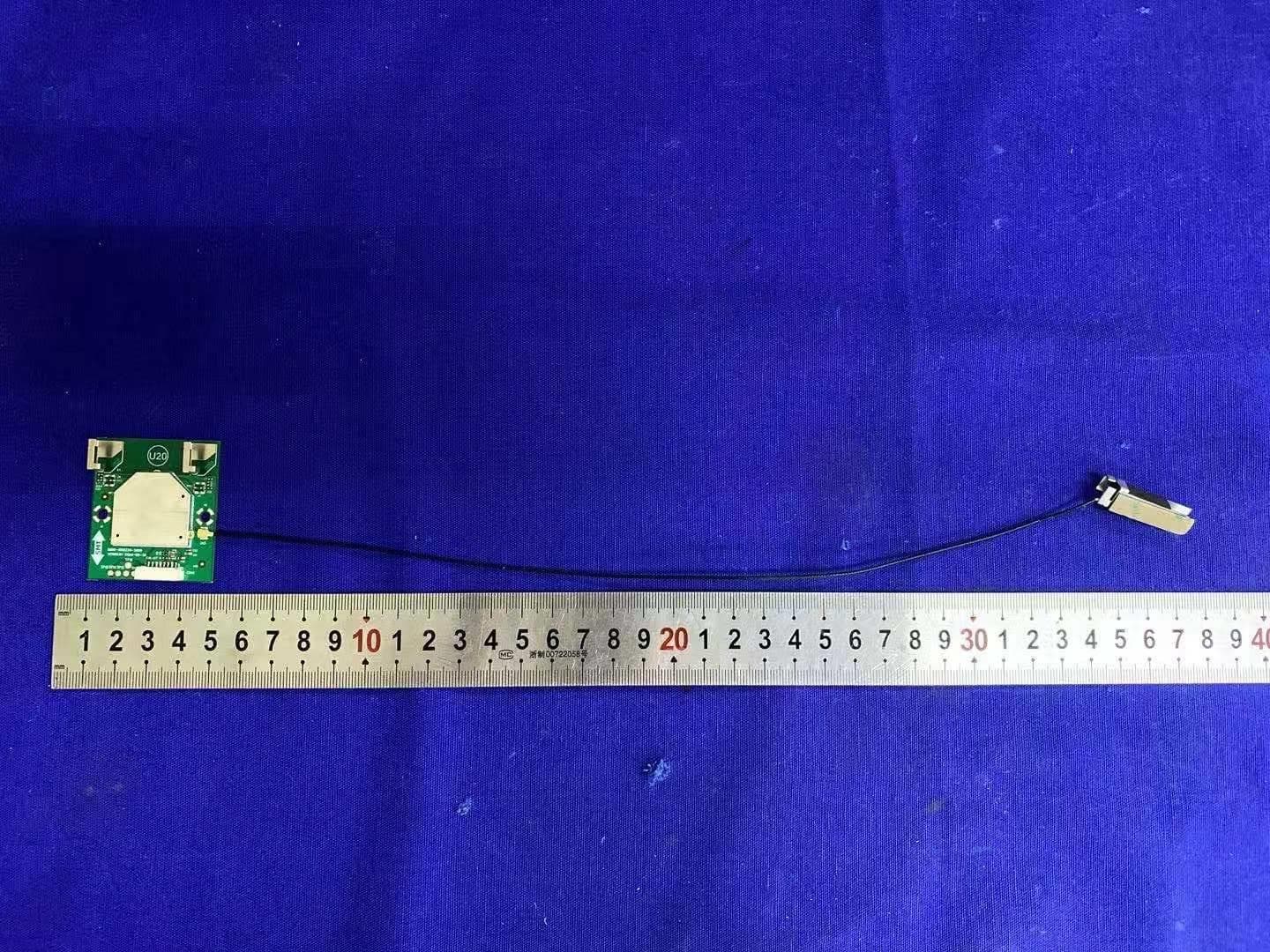
Click to zoom
Application Details
- Equipment Class
- DTS - Digital Transmission System
- Date of Grant
- Nov 21, 2020
- Application Purpose
- Original Equipment
- Date of Application
- Nov 21, 2020
- Equipment Note
- Wireless Module
- Frequency Range
- 2422.00000000 - 2452.00000000
- Country
- China
Documents & Files
Document Text
Text extracted from the exhibit documents filed with the FCC. Open a document above to read the original.
Users Manual
Shenzhen skyworth RGB electronic co., LTD. Model: NTUD - U20 Operation Instruction Respect of customer, sincerely thank you for purchasing SKYWORTH equipped with wireless WIFI NTUD - U20 - type USB peripheral products. This product can support USB2.0 protocol, based on the IEEE802.11 a/b/g/n/ac BT5.0 standard design. With all the way to send and receive all the way (2T2R) dual channel work, maximum transmission rate of up to 866 Mbps.Ensure that users browse and download data flow, security and stability. NTUD - U20 wireless WIFI USB peripheral product support Windows XP/Vista / 7 / Linux operating system.In SKYWORTH TV, have complete embedded in the product and the driver, without user to install, and at the same time support Linux and Android. Used in TV production operation is as follows: 1. Turn on the TV, switch to the "home page" interface. 2. Select "Settings" feature. "OK" to enter 3. Select "network setup" function. "OK" to enter; 4. Choose the "wireless network", "OK" to enter; 5. According to the needs, select "auto search", "manual connection", etc. Press the "OK" to enter 6. Choose their own after the AP name "OK" to enter, Enter the password. Television system has the memory function, for the first time to use should be according to the above steps, later need not operation, boot automatically connected.If need to change the AP or change the mode of connection, need according to the above steps again. Note: This equipment has been tested and found to comply with the limits for a Class B digital device, pursuant to Part 15 of the FCC Rules. These limits are designed to provide reasonable protection against harmful interference in a residential installation. This equipment generates, uses and can radiate radio frequency energy and, if not installed and used in accordance with the instructions, may cause harmful interference to radio communications. However, there is no guarantee that interference will not occur in a particular installation. If this equipment does cause harmful interference to radio or television reception, which can be determined by turning the equipment off and on, the user is encouraged to try to correct the interference by one or more of the following measures: - Reorient or relocate the receiving antenna. - Increase the separation between the equipment and receiver. - Connect the equipment into an outlet on a circuit different from that to which the receiver is - connected. - Consult the dealer or an experienced radio/television technician for help. To assure continued compliance, any changes or modifications not expressly approved by the party responsible for compliance could void the user’s authority to operate this equipment. FCC Radiation Exposure Statement This equipment complies with FCC RF radiation exposure limits set forth for an uncontrolled environment. This device complies with Part 15 of the FCC Rules. Operation is subject to the following two conditions: (1) This device may not cause harmful interference, and (2) This device must accept any interference received, including interference that may cause undesired operation. Regulation Information 1) List of applicable FCC rules: FCC part 15.249 FCC part 15.247 FCC part 15.407 2) Summarize the specific operational use conditions This Device and its antenna must not be co-located or operating in conjunction with any other antenna or transmitter. The host product manufacturer should state this information to the host instruction manual. 3) Limited module procedures: No applicable. 4)Trace antenna designs No applicable. 5) RF exposure considerations This equipment complies with FCC RF radiation exposure limits set forth for an uncontrolled environment, and minimum of 20cm separation between antenna and body. The host product shall show the same or similar statement to the end users. 6) Antennas Antenna types not included in this list, having a gain greater than the maximum gain indicated For that type, are strictly prohibited for use with this device. Antenna type: Integral Antenna Bluetooth Antenna Max. Gain: 2.0dBi Each 2.4G WIFI Antenna Max. Gain: 3.1dBi Each 5G WIFI Antenna Max. Gain: 2.26dBi 7) Label and compliance information The end product must carry a label stating “Contains Transmitter Module FCC ID: 2ANM3NTUDU20 ”or shall use e-labeling. 8) Information on test modes and additional testing requirements The host manufacturer can use the software “MPTool, Version: 9.02” and “ RTLBTAPP, Version: 5.2.2.75 ” for access to the test modes. Connected to the computer through the serial port of the host product, the channel and power controlling software provided by the applicant was used to control the operating channel as well as the output power level. The RF output power selection is for the setting of RF output power expected by the application and is going to be fixed on the firmware of the end product. 9) Additional testing, Part 15 Subpart B disclaimer The modular transmitter is only FCC authorized for the specific rule parts (FCC Part 15.249&15.247&15.407) list on the grant, and that the host product manufacturer is responsible for compliance to any other FCC rules that apply to the host not covered by the modular transmitter grant of certification. The final host product still requires Part 15 Subpart B compliance testing with the modular transmitter installed when contains digital circuity. 10) The device is going to be operated in 5150~5250MHz frequency range. It is restricted indoor environment only. 11) The device working temperature 0°C to +60°C 12) The device working voltage 3.3V±10% 13) Manual Information to the End User The OEM integrator has to be aware not to provide information to the end user regarding how to install or remove this RF module in the user’s manual of the end product which integrates this module.
Attestation Statements
1(2) Shenzhen Chuangwei-RGB Electronics Co., Ltd. RE FCC ID: 2ANM3NTUDU20 To the certification reviewer: We are hereby applying for full modular approval of the above-referenced FCC ID, based on compliance with all of the criteria as detailed below. Sincerely, _________________ Dan Fang Senior Manager 2020.10.30 Part 15 Unlicensed Single Modular Transmitter Approval Justifications per 15.212 Requirement per 15.212 Description (i) The radio elements of the modular transmitter must have their own RF shielding. Shielding is provided by a metal cover the circuitry. (ii) The modular transmitter must have buffered modulation/data inputs. All modulation and data inputs are buffered by circuitry on the transmitter chip. (iii) The modular transmitter must have its own power supply regulation. Power supply regulation is provided by circuitry on the transmitter chip. (iv) The modular transmitter must comply with the antenna and transmission system requirements of §§ 15.203, 15.204(b) and 15.204(c). The Wi-Fi antennas are permanently attached. The Bluetooth antenna is a type of unique coupling. (v) The modular transmitter must be tested in a stand-alone configuration, i.e., the module must not be inside another device during testing for compliance with Part 15 requirements. Testing was performed with the module extended outside of the host on a special extender boards, as shown in the test setup photos. 2(2) (vi) The modular transmitter must be equipped with either a permanently affixed label or must be capable of electronically displaying its FCC identification number. If the FCC ID is not visible when the module is installed inside another device, then the outside of the device into which the module is installed must also display a label referring to the enclosed module. See KDB Publication 784748. A sample of the host label is provided as an exhibit, showing the FCC ID of the module. (vii) The modular transmitter must comply with any specific rules or operating requirements that ordinarily apply to a complete transmitter and the manufacturer must provide adequate instructions along with the module to explain any such requirements. A copy of these instructions must be included in the application for equipment authorization. The modular transmitter complies with part 15 as demonstrated in the test report exhibit. (viii) The modular transmitter must comply with any applicable RF exposure requirements in its final configuration. The modular transmitter complies with RF exposure requirements as demonstrated in the RF exposure information exhibit.
Cover Letter(s)
ShenzhenChuangwei-RGBElectronicsCo.,Ltd. 2020.10.30 FederalCommunicationsCommission 44512 th StreetSW Washington,DC20554 Subject:LimitedAgencyAgreement (ShenzhenChuangwei-RGBElectronicsCo.,Ltd.) FCCID:2ANM3NTUDU20 ToWhomItMayConcern: We,ShenzhenChuangwei-RGBElectronicsCo.,Ltd.,herebyauthorizedIntertekTesting ServicestoactasourAgentforthepurposeofpreparingapplicationforFCCIDnumber 2ANM3NTUDU20underallapplicablepartsoftheFCCrulesandregulations. Theeffectivedateofthislimitedagencyagreementis(2020/10/30).TheLimitedAgency Agreementexpireson(2021/10/30),unlesssoonerterminatedorextendedbywrittennoticeto IntertekTestingServicesandtheFederalCommunicationsCommission. ThisistoadvisethatweareinfullcompliancewiththeAnti-DrugAbuseAct.Theapplicantis notsubjecttoadenialoffederalbenefitspursuanttoSection5301oftheAnti-DrugActof1988, 21U.S.C.862,andnopartytotheapplicationissubjecttoadenialoffederalbenefitspursuantto thatsection. Ifyouhaveanyquestionsorcomments,pleasedonothesitatetocontactme. Sincerely, DanFang SeniorManager
Cover Letter(s)
1 ( 2 ) ShenzhenChuangwei-RGBElectronicsCo.,Ltd. Attention:Certificationreviewer RE:RequestforConfidentiality FCCID:2ANM3NTUDU20 ToWhomItMayConcern: PermanentConfidentiality[Completethissectionifpermanentconfidentialityisrequested] Requesttowithholdpermanentlyfrompublicreviewcertainportionsoftheapplicationforequipment certificationforthereferencedFCCidentifiers.Thisrequestforconfidentialityismadepursuantto47CFR 0.457(d)and0.459oftheFCCRules.Inparticular,thefollowingsectionsoftheapplicationaretobekept permanentlyconfidential: [Selectoneormoreofitemsbelow,asappropriate] Schematics BlockDiagrams OperationalDescription Tune-upProcedure PartsList InternalPhotos(seenote) UsersManual(seenote) Note1:InternalPhotosmaybeheldconfidential1)ifthecircuitboardorinternalcomponentsarenotaccessibletousers.For example,itisacceptableifthecircuitboardisenclosedinepoxy.2)Also,itisacceptableifthedeviceisnot accessibletothepublic,forexample,adevicemountedonthetopofalargetower(orinafencedenclosure)such thatitisonlyserviceablebyprofessionaldesignatedtechniciansunderaNon-DisclosureAgreement(NDA).All salesforthesedevicesmustbeunderaNDArestrictingthedisclosureoftheproprietyinformation,including internalphotos. UsersManualmaybeheldconfidentialonlywhenthemanualcontainsproprietarytechnicalinformationintended forprofessionaltechniciansobligatedunderaNDA.Allsalesanddistributionoftheuser’smanualmustbeundera NDAthatrestrictsthedisclosureoftheinformation. IntheapplicationcoverletterrequestingpermanentconfidentialitythefollowingadditionaldescriptionandtheNDA exhibitisrequired: 1.Describeindetailhowinternalphotosand/orusersmanualinformationarecontrolledtopreventthemfrom becomingpublicordisclosedtounauthorizedpersons. 2.Describehowpublicaccessisrestrictedforproductsserviceablebyprofessionaldesignatedtechnicians. 3.Astatementthatallsalesofthenon-consumerdevicewillbeunderaNDAtoincludethirdpartysalesandthatthe finaluserofthedeviceissubjecttotheNDA. 4.ProvideanexampleoftheNDAbetweenthegranteeandapurchaser.Therequestforconfidentialitymust Note2:Forscanningreceiver,theschematics,blockdiagrams,operationaldescription,tune-upprocedure,partslistand internalphotosarealwaysheldpermanentlyconfidential. Short-termConfidentiality[Completethissectionifshort-termconfidentialityisrequested] Requesttowithholdfrompublicreviewforaperiodof[pleaseenter1to180]daysfromthedateoftheGrant ofEquipmentAuthorizationandpriortomarketing,certainportionsoftheapplicationforequipment certificationforthereferencedFCCidentifiers.Thisrequestforconfidentialityismadepursuantto47CFR 0.457(d)and0.459oftheFCCRules.Inparticular,thefollowingsectionsoftheapplicationaretobekept short-termconfidentialforaperiodabovefromthedateofthegrant [Selectoneormoreofitemsbelowthatarenotselectedinthelistabove,asappropriate] Schematics Blockdiagrams OperationalDescription Tune-upProcedure PartsList 2 ( 2 ) TestSetupPhotos ExternalPhotos InternalPhotos UsersManual Rationaleforrequestforconfidentiality: Wehaveinvestedconsiderabletimeandmaterialsinresearchanddevelopmenttoproducethereferenced product. Permanentconfidentiality:Disclosureofthepermanentlyconfidentialportionsofthisapplicationto competitorswouldnotonlygivethemsignificantcompetitiveadvantagesindevelopingsimilarproducts,but wouldalsodisclosesuccessfulimplementationofunpublished,leadingedgetechnologydevelopedbyus. Short-termconfidentiality:Disclosureoftheshort-termconfidentialportionsofthisapplicationduring theperiodofimportationand/ordistributionwouldrevealkeyaspectsofproprietarytechnologyto competitorsanddiminishthevalueofourinvestmentinresearchanddevelopment. Ifyouhavequestionsorneedfurtherinformation,pleasecontacttheundersigned. Sincerely, _________________ DanFang SeniorManager 2020.10.30
External Photos
External Photos BT Antenna ComTool
ID Label/Location Info
Skyworth NTUD-U20 FCC ID:2ANM3NTUDU20 IC :23165-NTUDU20 Size:26mm*10mm
Internal Photos
Internal Photos 2.4G&5.2G WiFi Antenna 1 2.4G&5.2G WiFi Antenna 2 BT Antenna
RF Exposure Info
INTERTEK TESTING SERVICES RF Exposure The equipment under test (EUT) is a wireless module with Bluetooth 5.0 (dual-mode) function operating in 2402-2480MHz, 2.4G WIFI function operating in 2412-2462MHz and 5G WIFI function operating in 5150MHz~5250 MHz, 5250MHz~5350MHz, 5470MHz-5725MHZ, 5725MHz~5850MHz. The EUT is powered by DC 3.3V. For more detail information pls. refer to the user manual. Bluetooth Version: 5.0 EDR mode. Antenna Type: Integral antenna. Antenna Gain: 2.0dBi. Modulation Type: GFSK, π/4DQPSK, 8DPSK. The nominal conducted output power specified: 6.0dBm (+/-3dB) The nominal radiated output power (e.i.r.p) specified: 8.0dBm (+/- 3dB) According to the KDB 447498: The maximun peak radiated emission for the EUT is 105.8dBμV/m at 3m in the frequency 2402MHz The EIRP = [(FS*D) ^2 / 30] mW = 10.57dBm which is within the production variation. The minimum peak radiated emission for the EUT is 101.5dBμV/m at 3m in the frequency 2441MHz The EIRP = [(FS*D) ^2 / 30] mW = 6.27dBm which is within the production variation. According to FCC Part 2.1091, this unlicensed transmitting devices is categorically excluded from routine environmental evaluation for RF exposure prior to equipment authorization or use, According to the KDB 447498 and OET 65, the simple calculation as below: The source-based time averaged maximum radiated power = 8dBm+3dBi = 11dBm = 12.59mW From above data, the exposed power density at a distance (R) of 20cm from the center of radiation of the antenna for 5.0 BLE mode can be calculated according to OET 65 as follow: = 12.59mW/ 4πR^2 = 0.003 mW/cm^2 <1mW/cm^2 The MPE limit is 1.0 mW/cm^2 for general population and uncontrolled exposure in the Bluetooth frequency range according to FCC Part 1.1310. As the measured power density at 20cm from the transmitter is lower than the MPE limit, the compliance to the MPE limit can be ensured by indicating the minimum 20cm separation between the transmitter's radiating structure and body of the user or nearby persons. FCC ID: 2ANM3NTUDU20 INTERTEK TESTING SERVICES Bluetooth Version: 5.0 BLE mode. Antenna Type: Integral antenna. Antenna Gain: 2.0dBi. Modulation Type: GFSK. The nominal conducted output power specified: 7.0dBm (+/-3dB) The maximun conducted output power for the EUT is 9.13dBm in the frequency 2480MHz which is within the production variation. The minimum conducted output power for the EUT is 8.14dBm in the frequency 2402MHz which is within the production variation. According to FCC Part 2.1091, this unlicensed transmitting devices is categorically excluded from routine environmental evaluation for RF exposure prior to equipment authorization or use, According to the KDB 447498 and OET 65, the simple calculation as below: The source-based time averaged maximum radiated power = 12dBm = 15.85mW From above data, the exposed power density at a distance (R) of 20cm from the center of radiation of the antenna for 2.4GHz band can be calculated according to OET 65 as follow: = 15.85mW/ 4 πR^2 = 0.003 mW/cm^2 <1mW/cm^2 The MPE limit is 1.0 mW/cm^2 for general population and uncontrolled exposure in the Bluetooth frequency range according to FCC Part 1.1310. As the measured power density at 20cm from the transmitter is lower than the MPE limit, the compliance to the MPE limit can be ensured by indicating the minimum 20cm separation between the transmitter's radiating structure and body of the user or nearby persons. FCC ID: 2ANM3NTUDU20 INTERTEK TESTING SERVICES 2.4GHz WiFi: Antenna Type: Integral Antenna. Antenna Gain: 3.1dBi. Directional Gain: 6.1dBi Modulation Type: BPSK, QPSK, 16QAM, 64QAM, CCK, DQPSK, DBPSK and DSSS. The nominal conducted output power specified: 17dBm (Tolerance: +/-3dB). The maximun conducted output power for the EUT is 15.1dBm in the frequency 2437MHz(802.11 n-HT20, SISO mode) which is within the production variation. The minimum conducted output power for the EUT is 18.2dBm in the frequency 2422MHz(802.11 n-HT40, MIMO mode) which is within the production variation. According to FCC Part 2.1091, this unlicensed transmitting devices is categorically excluded from routine environmental evaluation for RF exposure prior to equipment authorization or use, According to the KDB 447498 and OET 65, the simple calculation as below: The source-based time averaged maximum radiated power = 26.1dBm = 407.4mW From above data, the exposed power density at a distance (R) of 20cm from the center of radiation of the antenna for 2.4GHz band can be calculated according to OET 65 as follow: = 407.4mW/ 4 πR^2 = 0.081 mW/cm^2 <1mW/cm^2 The MPE limit is 1.0 mW/cm^2 for general population and uncontrolled exposure in the Bluetooth frequency range according to FCC Part 1.1310. As the measured power density at 20cm from the transmitter is lower than the MPE limit, the compliance to the MPE limit can be ensured by indicating the minimum 20cm separation between the transmitter's radiating structure and body of the user or nearby persons. FCC ID: 2ANM3NTUDU20 INTERTEK TESTING SERVICES 5GHz WiFi: Antenna Type: Integral Antenna. Antenna Gain: 2.26dBi for each antenna Directional Gain: 5.27dBi Modulation Type: BPSK, QPSK, 16QAM, 64QAM and OFDM. The nominal conducted output power specified: 17dBm (Tolerance: +/-6dB). The maximun conducted output power for the EUT is 11.23dBm in the frequency 5670MHz(802.11 ac-HT40, SISO mode) which is within the production variation. The minimum conducted output power for the EUT is 19.2dBm in the frequency 5180MHz(802.11 n-HT20, MIMO mode) which is within the production variation. According to FCC Part 2.1091, this unlicensed transmitting devices is categorically excluded from routine environmental evaluation for RF exposure prior to equipment authorization or use, According to the KDB 447498 and OET 65, the simple calculation as below: The source-based time averaged maximum radiated power = 28.27dBm = 671.43mW From above data, the exposed power density at a distance (R) of 20cm from the center of radiatio…
Text truncated - open the document above for the full version.
Test Report
Shenzhen Chuangwei-RGB Electronics Co., Ltd. TEST REPORT SCOPE OF WORK FCC TESTING – NTUD-U20 REPORT NUMBER 201019016SZN-002 ISSUE DATE [REVISED DATE] 5 November 2020 [--------------------] PAGES 34 DOCUMENT CONTROL NUMBER FCC ID 247_b © 2017 INTERTEK Intertek Report No.: 201019016SZN-002 This report is for the exclusive use of Intertek's Client and is provided pursuant to the agreement between Intertek and its Client. Intertek's responsibility and liability are limited to the terms and conditions of the agreement. Intertek assumes no liability to any party, other than to the Client in accordance with the agreement, for any loss, expense or damage occasioned by the use of this report. Only the Client is authorized to permit copying or distribution of this report and then only in its entirety. Any use of the Intertek name or one of its marks for the sale or advertisement of the tested material, product or service must first be approved in writing by Intertek. The observations and test results in this report are relevant only to the sample tested. This report by itself does not imply that the material, product, or service is or has ever been under an Intertek certification program. Intertek Testing Services Shenzhen Ltd. Longhua Branch 101, 201, Building B, No. 308 Wuhe Avenue, Zhangkengjing Community, GuanHu Subdistrict, LongHua District, Shenzhen, P.R. China. Tel: (86 755) 8601 6288 Fax: (86 755) 8601 6751 Version: 01-November-2017 Page: 1 of 34 FCC ID 247_b TEST REPORT 101, 201, Building B, No. 308 Wuhe Avenue, Zhangkengjing Community, GuanHu Subdistrict, LongHua District, Shenzhen, P.R. China. Tel: (86 755) 8601 6288 Fax: (86 755) 8601 6751 www.intertek.com Shenzhen Chuangwei-RGB Electronics Co., Ltd. Application For Certification FCC ID: 2ANM3NTUDU20 Wireless Module Model: NTUD-U20 2.4GHz Wi-Fi Transceiver Report No.: 201019016SZN-002 We hereby certify that the sample of the above item is considered to comply with the requirements of FCC Part 15, Subpart C for Intentional Radiator, mention 47 CFR [10-1-19] Prepared and Checked by: Approved by: Leo Li Kidd Yang Project Engineer Technical Supervisor Date: 5 November 2020 TEST REPORT Intertek Report No.: 201019016SZN-002 Version: 01-November-2017 Page: 2 of 34 FCC ID 247_b MEASUREMENT/TECHNICAL REPORT This report concerns (check one) Original Grant X Class II Change Equipment Type: DTS - Part 15 Digital Transmission Systems (Wi-Fi transmitter portion) Deferred grant requested per 47 CFR 0.457(d)(1)(ii)? Yes No X If yes, defer until : date Company Name agrees to notify the Commission by: date of the intended date of announcement of the product so that the grant can be issued on that date. Transition Rules Request per 15.37? Yes No X If no, assumed Part 15, Subpart C for intentional radiator - the new 47 CFR [10-01- 19] Edition] provision. Report prepared by: Leo Li Intertek Testing Services Shenzhen Ltd. Longhua Branch 101, 201, Building B, No. 308 Wuhe Avenue, Zhangkengjing Community, GuanHu Subdistrict, LongHua District, Shenzhen, P.R. China. Tel: (86 755) 8614 0743 Fax: (86 755) 8601 6661 TEST REPORT Intertek Report No.: 201019016SZN-002 Version: 01-November-2017 Page: 3 of 34 FCC ID 247_b Table of Contents 1.0 Summary of Test results ............................................................................................... 4 2.0 General Description ..................................................................................................... 5 2.1 Product Description .......................................................................................................... 5 2.2 Related Submittal(s) Grants .............................................................................................. 5 2.3 Test Methodology ............................................................................................................. 5 2.4 Test Facility ....................................................................................................................... 5 3.0 System Test Configuration ............................................................................................ 6 3.1 Justification ....................................................................................................................... 6 3.2 EUT Exercising Software .................................................................................................... 6 3.3 Special Accessories ............................................................................................................ 6 3.4 Measurement Uncertainty ................................................................................................ 7 3.5 Equipment Modification ................................................................................................... 7 3.6 Support Equipment List and Description ......................................................................... 7 4.0 Measurement Results .................................................................................................. 8 4.1 Maximum Conducted Output Power at Antenna Terminals ................................................ 8 4.2 Minimum 6 dB RF Bandwidth ............................................................................................ 9 4.3 Maximum Power Density Reading .................................................................................. 11 4.4 Out of Band Conducted Emissions................................................................................... 13 4.5 Out of Band Radiated Emissions ...................................................................................... 19 4.6 Transmitter Radiated Emissions in Restricted Bands ....................................................... 20 4.7 Field Strength Calculation................................................................................................ 21 4.8 Radiated Spurious Emission ........................................................................................…
Text truncated - open the document above for the full version.
Contact Information
Applicant
Dan Fang
Technical Contact
Intertek Testing Services Shenzhen LtdWilliam Chen
[email protected]86-755-86016288
101,201,Bldg B, No.308 Wuhe Ave, Zhangkenging Comm · Shenzhen · China
Non-Technical Contact
Intertek Testing Services Shenzhen LtdWilliam Chen
[email protected]86-755-86016288
Test Firm
Intertek Testing Services Shenzhen Ltd. Longhua BrHolly Ou
[email protected]+86 755 86140691
Technical Specifications
| # | Rule Parts | Frequency Range | Power Output |
|---|---|---|---|
| 3 | 15C | 2.42 GHz - 2.45 GHz | 66.07 mW |
Other Applications from Shenzhen Chuangwei-RGB Electronics Co., Ltd.
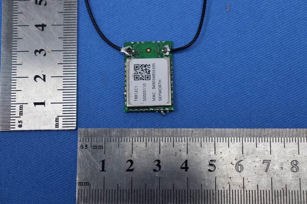
2ANM3T8812C1
Jul 21, 2024WIFI Module
Equipment Class
DTS - Digital Transmission System2ANM3HS8G
Apr 07, 2024Remote Controller
Equipment Class
DTS - Digital Transmission System2ANM3HS7AB
Mar 30, 2024Remote Controller
Equipment Class
DSS - Part 15 Spread Spectrum Transmitter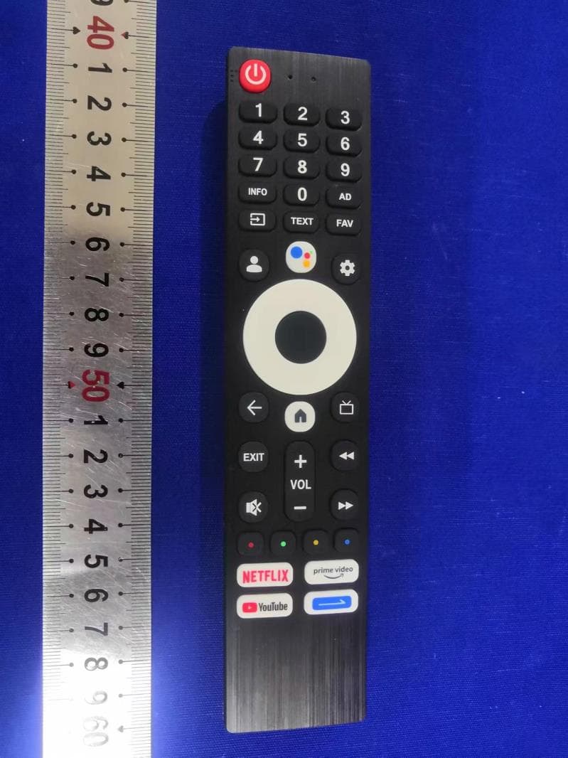
2ANM3HS8C
Aug 15, 2022HS-8C remote control
Equipment Class
DTS - Digital Transmission System
2ANM3NHS8A
Jun 01, 2021Bluetooth remote control
Equipment Class
DTS - Digital Transmission System